Hitachi SP18VA Handling Instructions Manual
- Category
- Power tools
- Type
- Handling Instructions Manual

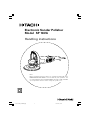
Electronic Sander Polisher
Model SP 18VA
Handling instructions
Note:
Before using this Electric Power Tool, carefully read through these
HANDLING INSTRUCTIONS to ensure efficient, safe operation. It is
recommended that these INSTRUCTIONS be kept readily available
as an important reference when using this power tool.
001CoverF_SP18VA_Eng 10/17/07, 17:041

2
GENERAL SAFETY RULES
WARNING!
Read all instructions
Failure to follow all instructions listed below may result in
electric shock, fire and/or serious injury.
The term “power tool” in all of the warnings listed below
refers to your mains operated (corded) power tool or battery
operated (cordless) power tool.
SAVE THESE INSTRUCTIONS
1) Work area
a) Keep work area clean and well lit.
Cluttered and dark areas invite accidents.
b) Do not operate power tools in explosive
atmospheres, such as in the presence of flammable
liquids, gases or dust.
Power tools create sparks which may ignite the
dust of fumes.
c) Keep children and bystanders away while operating
a power tool.
Distractions can cause you to lose control.
2) Electrical safety
a) Power tool plugs must match the outlet.
Never modify the plug in any way.
Do not use any adapter plugs with earthed
(grounded) power tools.
Unmodified plugs and matching outlets will reduce
risk of electric shock.
b) Avoid body contact with earthed or grounded
surfaces such as pipes, radiators, ranges and
refrigerators.
There is an increased risk of electric shock if your
body is earthed or grounded.
c) Do not expose power tools to rain or wet
conditions.
Water entering a power tool will increase the risk
of electric shock.
d) Do not abuse the cord. Never use the cord for
carrying, pulling or unplugging the power tool.
Keep cord away from heat, oil, sharp edges or
moving parts.
Damaged or entangled cords increase the risk of
electric shock.
e) When operating a power tool outdoors, use an
extension cord suitable for outdoor use.
Use of a cord suitable for outdoor use reduces
the risk of electric shock
3) Personal safety
a) Stay alert, watch what you are doing and use
common sense when operating a power tool.
Do not use a power tool while you are tired or
under the influence of drugs, alcohol or medication.
A moment of inattention while operating power
tools may result in serious personal injury.
b) Use safety equipment. Always wear eye protection.
Safety equipment such as dust mask, non-skid
safety shoes, hard hat, or hearing protection used
for appropriate conditions will reduce personal
injuries.
c) Avoid accidental starting. Ensure the switch is in
the off position before plugging in.
Carrying power tools with your finger on the
switch or plugging in power tools that have the
switch on invites accidents.
d) Remove any adjusting key or wrench before
turning the power tool on.
A wrench or a key left attached to a rotating part
of the power tool may result in personal injury.
e) Do not overreach. Keep proper footing and balance
at all times.
This enables better control of the power tool in
unexpected situations.
f) Dress properly. Do not wear loose clothing or
jewellery. Keep your hair, clothing and gloves
away from moving parts.
Loose clothes, jewellery or long hair can be caught
in moving parts.
g) If devices are provided for the connection of dust
extraction and collection facilities, ensure these
are connected and properly used.
Use of these devices can reduce dust related hazards.
4) Power tool use and care
a) Do not force the power tool. Use the correct
power tool for your application.
The correct power tool will do the job better and
safer at the rate for which it was designed.
b) Do not use the power tool if the switch does not
turn it on and off.
Any power tool that cannot be controlled with the
switch is dangerous and must be repaired.
c) Disconnect the plug from the power source before
making any adjustments, changing accessories, or
storing power tools.
Such preventive safety measures reduce the risk
of starting the power tool accidentally.
d) Store idle power tools out of the reach of children
and do not allow persons unfamiliar with the
power tool or these instructions to operate the
power tool.
Power tools are dangerous in the hands of
untrained users.
e) Maintain power tools. Check for misalignment or
binding of moving parts, breakage of parts and
any other condition that may affect the power
tools operation.
If damaged, have the power tool repaired before
use.
Many accidents are caused by poorly maintained
power tools.
f) Keep cutting tools sharp and clean.
Properly maintained cutting tools with sharp cutting
edges are less likely to bind and are easier to
control.
g) Use the power tool, accessories and tool bits etc.,
in accordance with these instructions and in the
manner intended for the particular type of power
tool, taking into account the working conditions
and the work to be performed.
Use of the power tool for operations different from
intended could result in a hazardous situation.
5) Service
a) Have your power tool serviced by a qualified repair
person using only identical replacement parts.
This will ensure that the safety of the power tool
is maintained.
PRECAUTION
Keep children and infirm persons away.
When not in use, tools should be stored out of reach of
children and infirm persons.
01Eng_SP18VA_Eng 10/17/07, 17:042

3
SAFETY WARNINGS COMMON FOR
GRINDING OR POLISHING OPERATIONS
a) This power tool is intended to function as a grinder
or polisher tool. Read all safety warnings,
instructions, illustrations and specifications provided
with this power tool.
Failure to follow all instructions listed below may
result in electric shock, fire and/or serious injury.
b) Operations such as sanding, wire brushing or
cutting-off are not recommended to be performed
with this power tool.
Operations for which the power tool was not
designed may create a hazard and cause personal
injury.
c) Do not use accessories which are not specifically
designed and recommended by the tool
manufacturer.
Just because the accessory can be attached to your
power tool, it does not assure safe operation.
d) The rated speed of the accessory must be at least
equal to the maximum speed marked on the power
tool.
Accessories running faster than their rated speed
can break and fly apart.
e) The outside diameter and the thickness of your
accessory must be within the capacity rating of
your power tool.
Incorrectly sized accessories cannot be adequately
guarded or controlled.
f) The arbour size of wheels, flanges, backing pads
or any other accessory must properly fit the spindle
of the power tool.
Accessories with arbour holes that do not match
the mounting hardware of the power tool will run
out of balance, vibrate excessively and may cause
loss of control.
g) Do not use a damaged accessory. Before each use
inspect the accessory such as abrasive wheels for
chips and cracks, backing pad for cracks, tear or
excess wear, wire brush for loose or cracked wires.
If power tool or accessory is dropped, inspect for
damage or install an undamaged accessory. After
inspecting and installing an accessory, position
yourself and bystanders away from the plane of
the rotating accessory and run the power tool at
maximum no-load speed for one minute.
Damaged accessories will normally break apart
during this test time.
h) Wear personal protective equipment. Depending on
application, use face shield, safety goggles or safety
glasses. As appropriate, wear dust mask, hearing
protectors, gloves and workshop apron capable of
stopping small abrasive or workpiece fragments.
The eye protection must be capable of stopping
flying debris generated by various operations. The
dust mask or respirator must be capable of filtrating
particles generated by your operation. Prolonged
exposure to high intensity noise may cause hearing
loss.
i) Keep bystanders a safe distance away from work
area. Anyone entering the work area must wear
personal protective equipment.
Fragments of workpiece or of a broken accessory
may fly away and cause injury beyond immediate
area of operation.
j) Hold power tool by insulated gripping surfaces
only, when performing an operation where the
cutting accessory may contact hidden wiring or its
own cord.
Cutting accessory contacting a “live” wire may make
exposed metal parts of the power tool “live” and
shock the operator.
SAFETY WARNINGS SPECIFIC FOR SANDING
OPERATIONS
a) Do not use excessively oversized sanding disc paper.
Follow manufacturers recommendations, when
selecting sanding paper.
Larger sanding paper extending beyond the sanding
pad presents a laceration hazard and may cause
snagging, tearing of the disc or kickback.
SAFETY WARNINGS SPECIFIC FOR
POLISHING OPERATIONS
a) Do not allow any loose portion of the polishing
bonnet or its attachment strings to spin freely.
Tuck away or trim any loose attachment strings.
Loose and spinning attachment strings can entangle
your fingers or snag on the workpiece.
PRECAUTIONS ON USING ELECTRONIC
SANDER POLISHER
1. Never mount a grinding wheel and attempt to use
this tool as a disc grinder.
2. Always hold the body handle and side handle of
the power tool firmly
Otherwise the counterforce produced may result in
inaccurate and even dangerous operation.
3. Ensure that sparks resulting from use do not create
a hazard e. g. do not hit persons, or ignite flammable
substances.
4. Always use protective safety glasses and hearing
protectors, use other personal protective equipment
such as gloves, apron and helmet when necessary.
5. Always use eye and ear protection.
Other personal protective equipment such as dust
mask, gloves, helmet and apron should be worn
when necessary.
If in doubt, wear the protective equipment.
01Eng_SP18VA_Eng 10/17/07, 17:043

4
SPECIFICATIONS
Voltage (by areas)* (110V, 120V, 220V, 230V, 240V)
Power input 1250 W*
No load speed 0 – 3400min
-1
Sanding Disc Size outer dia. × inner dia. 180 × 22 mm
Weight (without cord, standard accessories) 2.8 kg
*Be sure to check the nameplate on product as it is subject to change by areas.
STANDARD ACCESSORIES
(1) Rubber Pad ................................................................ 1
(2) Loop Handle (with bolt and washer) ................... 1
(3) Bar Wrench ................................................................ 1
Standard accessories are subject to change without
notice.
APPLICATIONS
䡬 Grinding metal surfaces
䡬 Preliminary sanding of metal surfaces before
painting, rust removal, removing old paint before
repainting.
䡬 Finishing woodwork, correcting projections of timber
from joints or assemblies.
䡬 Preliminary sanding of wood surfaces before
applying paint.
䡬 Polishing or shining painted metal surfaces, such
as those of automobiles, trains, elevators,
refrigerators, sewing machines, washing machines,
metal appliances, etc.
䡬 Polishing varnished surfaces of wooden furniture,
etc.
䡬 Shining synthetic resin or ebonite products.
PRIOR TO OPERATION
1. Power source
Ensure that the power source to be utilized conforms
to the power requirements specified on the product
nameplate.
CAUTION
Do not operate on Direct Current power source.
2. Power switch
Ensure that the power switch is in the OFF position.
If the plug is connected to a receptacle while the
power switch is in the ON position, the power tool
will start operating immediately, which could cause
a serious accident.
3. Extension cord
When the work area is removed from the power
source, use an extension cord of sufficient thickness
and rated capacity. The extension cord should be
kept as short as practicable.
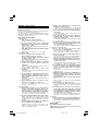
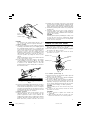
4. Confirm the lock pin
Confirm that the lock pin is disengaged by pushing
the lock pin two or three times before switching
the power tool on. (See Fig. 1)
5. Fixing the loop handle
Fix the loop handle with a bolt and a washer to
the gear cover.
PRACTICAL ELECTRONIC SANDER POLISHER
APPLICATIONS
Motor speed is increased by increasing pressure on
the trigger. Release the trigger to stop. For continuous
operation, pull the trigger and then push in the lock
button. To stop the motor from the locked position,
pull the trigger full, then release it.
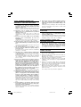
Motor speed can be variable as desired by rotating the
dial; it is increased by turning the dial towards “6”,
decreased by turning it towards “1” (Fig. 2).
Select the motor speed appropriate for the work being
done. The following table gives the motor speeds
corresponding to each indication on the dial scale and
shows the types of work for which they are suitable.
Dial
R.P.M. Type of work
Indication
1 600
2 1100
For Polishing
3 1700
4 2300
5 2900
For Sanding
6 3400
}
}
Fig. 1
Lock pin
01Eng_SP18VA_Eng 10/17/07, 17:044

5
CAUTION
The dial cannot be rotated further than the “6” or
“1” on the scale in their respective directions.
1. Sander operation
(1) This unit is designed to provide sufficient polishing
(sanding) power with the disc pressed lightly against
the sanding/polishing surface: it is equipped with
an electronic control circuit to ensure that the motor
will not slow down even when loaded. There is
therefore no need to press the sanding disc hard
against the surface; doing so can overload the motor,
subsequently causing the overload cut device to
step into operation by cutting the motor’s power
supply.
If this should happen, cut the power switch and turn
at the correct motor speed.
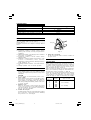
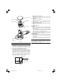
(2) Do not apply the entire disc surface to the surface
of the material. As shown in Fig. 3, the sander
should be held at an approximately 15° to 25° angle
in relation to the material surface so that the
peripheral portion of the sanding disc is offered to
the material surface.
Fig. 3
(3) Precaution immediately after finishing an operation:
After turning the switch OFF, do not put the sander
down until the sanding disc has come to a complete
stop. This precaution will not only prevent a serious
accident, but will also reduce the amount of dust
and swarf sucked into the machine.
2. Polisher operation:
(1) Curved surfaces as well as flat surfaces can be
efficiently finished. Do not excessively push the
polisher against the surface of the material. The
weight of the polisher alone is sufficient for effective
polishing. Excessive pressure will result in a poor
finish and cause possible overload to the motor.
(2) Sanding disc, polishing compound or wax should
be selected in accordance with the material and the
desired surface finish. Maximum polishing effect
will be attained by following the following method:
䡬 Preliminary polishing with sander using a finegrain
sanding disc.
䡬 Polishing with wool bonnet using polishing
compound and/or wax. Apply a small quantity of
compound and/or wax on material surface and polish
with the wool bonnet.
CAUTION
Carefully guard against permitting the cabtyre cord
to touch the wool bonnet or sanding disc during
operation. If the cord touches, there is a danger that
it may become entangled.
MOUNTING AND DISMOUNTING THE
SANDING DISC AND WOOL BONNET
1. For Sander operation (Fig. 4)
(1) After placing the sanding disc on the rubber pad,
thread the washer nut onto the spindle.
(2) Press the lock pin to secure the spindle and tighten
the washer nut with a wrench.
(3) To remove the sanding disc, follow the above
procedures in reverse.
Fig. 4
2. For Polisher operation (Fig. 5)
(1) Insert the washer nut through the rubber pad and
thread it onto the spindle.
(2) Press the lock pin to secure the spindle and tighten
the washer nut with a wrench.
(3) As shown in Fig. 6, wrap the rubber pad with the
hood of the wool bonnet, and firmly secure it by
tightening and tying its draw string. Be sure the
excess string is firmly tucked inside the wool bonnet
to prevent it from flying out while polishing.
CAUTION
Improper fitting of the wool bonnet may cause
vibration.
(4) To remove the wool bonnet, follow the above
procedures in reverse.
CAUTIONS
䡬 Use a wrench to tighten the washer nut
sufficiently.
䡬 After releasing the lock pin, check to be sure
that it has returned to its normal position.
15° – 25°
Fig. 2
Dial
Lock
button
Switch trigger
Washer nut
Sanding
disc
Rubber pad
Spindle
Lock pin
01Eng_SP18VA_Eng 10/17/07, 17:045

6
MAINTENANCE AND INSPECTION
1. Inspecting the mounting screws:
Regularly inspect all mounting screws and ensure
that they are properly tightened. Should any of the
screws be loose, retighten them immediately. Failure
to do so could result in serious hazard.
2. Inspecting the carbon brushes (Fig. 7)
The motor employs carbon brushes which are
consumable parts. Since an excessively worn carbon
brush can result in motor trouble, replace the carbon
brush with a new one having the same carbon
brush No. shown in the figure when it becomes
worn to or near the “wear limit”. In addition, always
keep carbon brushes clean and ensure that they
slide freely within the brush holders.
3. Replacing a carbon brush:
Disassemble the brush cap with a minus-head
screwdriver. The carbon brush can then be easily
removed.
4. Maintenance of the motor
The motor unit winding is the very “heart” of the
power tool.
Exercise due care to ensure the winding does not
become damaged and/or wet with oil or water.
5. Cleaning lock pin section
If the lock pin section becomes dirty, clean it at
once.
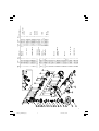
6. Service parts list
CAUTION
Repair, modification and inspection of Hitachi Power
Tools must be carried out by a Hitachi Authorized
Service Center.
This Parts List will be helpful if presented with the
tool to the Hitachi Authorized Service Center when
requesting repair or other maintenance.
In the operation and maintenance of power tools,
the safety regulations and standards prescribed in
each country must be observed.
MODIFICATIONS
Hitachi Power Tools are constantly being improved
and modified to incorporate the latest technological
advancements.
Accordingly, some parts (i.e. code numbers and/or
design) may be changed without prior notice.
NOTE
Due to HITACHI’s continuing program of research and
development, the specifications herein are subject to
change without prior notice.
Fig. 5
Fig. 6
Washer nut
Rubber pad
Wool bonnet
Spindle
Lock pin
Hood
Fig. 7
43
17 mm
6 mm
Tuck the
excess
string in
Wear limit
No. of carbon
brush
01Eng_SP18VA_Eng 10/17/07, 17:046

7
1
2
3
4
5
6
7
8
9
10
11
12
13
14
15
16
17
18
19
20
21
22
23
24
25
26
27
28
29
30
31
32
33
34
35
36
37
38
39
40
41
42
43
46
47
48
49
50
52
53
54
55
56
501
502
503
504
505
44
45
51
1 303-255 3 M4×10
2 305-507 4 D5×30
3 306-888 1
4 306-889 1
5 320-936 1 ”3, 4, 18-21”
6 315-055 1
7 315-054 1
8 939-540 1
9 620-0DD 1 6200DDCMPS2L
10 315-053 1
11 315-052 1
12 315-051 1
13 1 360-576U 1 110V-120V
”9, 11, 34, 38”
13 2 360-576E 1 220V-240V
14 315-046 1
15 961-501 2 D5×60
16 1 340-526C 1 110V ”17”
16 2 340-526E 1 220V-240V
17 930-703 2
18 315-049 1
19 320-218 1
20 315-050 1
21 871-397 1
22 320-937 1
23 987-201 3 M4×10
24 937-077 1
25 620-2DD 1 6202DDCMPS2L
26 940-533 1 3×3×10
27 320-943 1
28 315-062 1
29 315-060 1
30 315-061 1
31 315-636 4 M5×14
32 953-247Z 1
33 953-246Z 1
34 315-047 1
35 320-945 1 ”39, 41, 47, 48”
36 320-948 1
37 ———— 1
38 608-VVM 1 608VVC2PS2L
39 995-662 1
40 318-721 1
41 320-949 1
Item Code No.
No. No. Used Remarks
42 1 320-941 1
42 2 320-940 1 ”GBR (110V)”
43 305-095 2 D4×20
44 ———— 1
45 945-161 2
46 999-043 2
47 958-900 2
48 938-477 2 M5×8
49 320-939 1
50 320-938 1
51 302-099 4 D5×20
52 302-086 2 D4×20
53 984-750 2 D4×16
54 937-631 1
55 953-327 1
56 ———— 1
501 955-857 1 8MM
502 937-913Z 1
503 320-949 1
504 949-434 2 M10
505 949-844 2 M10×20
Item Code No.
No. No. Used Remarks
01Eng_SP18VA_Eng 10/17/07, 17:047

801
Code No. C99110311
Printed in Malaysia
Hitachi Koki Co., Ltd.
Shinagawa Intercity Tower A, 15-1, Konan 2-chome,
Minato-ku, Tokyo, Japan
01Eng_SP18VA_Eng 10/17/07, 17:048
-
 1
1
-
 2
2
-
 3
3
-
 4
4
-
 5
5
-
 6
6
-
 7
7
-
 8
8


Hitachi SP18VA Handling Instructions Manual
- Category
- Power tools
- Type
- Handling Instructions Manual
Ask a question and I''ll find the answer in the document
Finding information in a document is now easier with AI
Related papers
-
Hitachi SP 18VA Technical Data And Service Manual
-
Hitachi SP18VA User manual
-
-
-
-
-
-
-
-
Other documents
-
Makita PV7000C User manual
-
Rockwell ShopSeries RS4503 User manual
-
King Canada 8369B User manual
-
Makita 9207SPB User manual
-
Porter-Cable 7346 User manual
-
-
Porter-Cable 7346SP User manual
-
-
Porter Cable 7346 User manual
-
 WorkPro Angle Polisher User manual
