Page is loading ...

Polycom® VBP™ 4555 System
Hardware Guide
June 2011 | 3725-73545-001A

4555 Hardware Guide
1
Trademark Information
Polycom®, the Polycom “Triangles” logo, and the names and marks associated with Polycom’s products are trademarks and/or service marks of
Polycom, Inc., and are registered and/or common-law marks in the United States and various other countries.
All other trademarks are the property of their respective owners.
© 2010 Polycom, Inc. All rights reserved.
Polycom, Inc.
4750 Willow Road
Pleasanton, CA 94588-2708
USA
No part of this document may be reproduced or transmitted in any form or by any means, electronic or mechanical, for any purpose, without the
express written permission of Polycom, Inc. Under the law, reproducing includes translating into another language or format.
As between the parties, Polycom, Inc., retains title to and ownership of all proprietary rights with respect to the software contained within its
products. The software is protected by United States copyright laws and international treaty provision. Therefore, you must treat the software like
any other copyrighted material (e.g., a book or sound recording).
Every effort has been made to ensure that the information in this document is accurate. Polycom, Inc., is not responsible for printing or clerical
errors. Information in this document is subject to change without notice.

4555 Hardware Guide
2
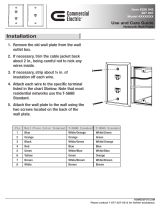
4555 VBP-E Series Physical connections and LED’s
Label Indication Status
Off Power is off – check the power adapter or AC outlet
A
Power
Green Power is supplied to the system
Off System self test failure
Green System self test passed - system is operation
B
Status
Flashing Green System is writing configuration changes or a system upgrade is in
progress
Off T1/E1 cable is not connected to the system
Green T1/E1 is in framing sync
Yellow Alarm Indicates the systems reception from the far end of a data or framing
pattern that reports the far end is in red alarm. For ESF framed signals,
all bits in the data link channel are framed as all 0’s (zero’s) e.g. the far
end does not see framing from this system.
C
T1/E1
Red Alarm Indicates the system is unable to recover the framing reliably and will
transmit a yellow alarm pattern to the far end.

4555 Hardware Guide
3
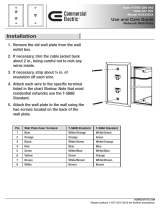
A
Power
Power plug for the DC power adapter to connect to the AC power source (included
in the system box)
B
LAN Interface’s
4 x 10/100 Mbps Ethernet port for LAN network connectivity
Default IP: 192.168.1.1
C
USB Currently not used
D
Erase
1 Click - Nothing
2 Clicks - Reset CLI password and restarts the system
3 Clicks - Restore to factory default
E
T1/E1 Status
LED functions as explained on the front panel in item “C”
F
T1/E1 WAN Interface
T1/E1 port is used to connect a network line for transmitting data to the far end
accepting TCP/IP encapsulation.
G
WAN Ethernet Interface
1 x 10/100 Mbps Ethernet port for connectivity to the WAN or Internet network
connectivity
Default IP: none
H
Console
1 x RS-232 DB9 console port for management – 9600-N-8-1 NONE for flow
control

4555 Hardware Guide
4
4555 VBP-E Series Ethernet LED’s
Label
Color Indication Status
Green or
other
On 1: Ethernet port is receiving power
2: Good link between the Ethernet port and the connected switch
Off 1: The adapter and switch are not receiving power
2: No connection between both ends of the network cable, check cable,
replace cable.
ACK/LINK
Green or
other
Flashing The adapter is sending and receiving network data. The frequency of the
flashing varies with the amount of data being transferred.
Green On ACK/LINK LED must be on. This LED will show the system operating at
100 Mbps
Speed
Off ACK/LINK LED must be on. This LED will show the system operating at
10 Mbps

4555 Hardware Guide
5
4555 VBP-E Series T1/E1 Pin Out to Network NIU or Smartjack
Pin
Signal EIA 568B To SmartJack EIA 568B Signal Pin
1
RX1 Ring - White/Orange RX1 -- > RX1 White/Orange RX1 Ring -
1
2
RX2 Ring + Orange RX2 -- > RX2 Orange RX2 Ring + 2
3
RX Ground White/Green RX Ground -- > RX Ground White/Green RX Ground 3
4
TX1 Ring - Blue TX1 -- > TX1 Blue TX1 Ring - 4
5
TX2 Ring + White/Blue TX2 -- > TX2 White/Blue TX2 Ring + 5
6
TX Ground Green TX Ground -- > TX Ground Green TX Ground 6
7
Not Used White/Brown Not used White/Brown Not Used 7
8
Not Used Brown Not Used Brown Not Used 8

4555 Hardware Guide
6
4555 VBP-E Series T1/E1 Crossover Pin out
Pin
Signal EIA 568B Crossover EIA 568B Signal Pin
1
RX1 Ring - White/Orange RX1 -- > TX1 Blue TX1 Ring -
4
2
RX2 Tip + Orange RX2 -- > TX2 White/Blue TX2 Tip + 5
3
RX Ground White/Green RX Ground -- > RX Ground White/Green RX Ground 3
4
TX1 Ring - Blue TX1 -- > RX1 White/Orange RX1 Ring - 1
5
TX2 Tip + White/Blue TX2 -- > RX2 Orange RX2 Tip + 2
6
TX Ground Green TX Ground -- > TX Ground Green TX Ground 6
7
Not Used White/Brown Not used White/Brown Not Used 7
8
Not Used Brown Not Used Brown Not Used 8

4555 Hardware Guide
7
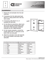
Connecting to the 4555 VBP-E Series for the First Time
The VBP Series appliance is shipped with a pre-configured IP address on Port 1 of 192.168.1.1
1. Connect the power adapter DC plug to the system (A) and the other end of the power adapter to the AC wall outlet.
2. Connect a computer using an IP address of 192.168.1.2 and subnet mask of 255.255.255.0 to any LAN port (B) shown in the above
figures with either a Ethernet switch or a Ethernet cable wired directly to the computer.
3. Launch a Web browser on the computer and enter http://192.168.1.1
Press Return. The main configuration menu appears - enter the
username "root" and the password "default."
4. The EULA license agreement will now be displayed. After reading the license agreement, click “I agree” at the bottom to continue
configuring the system.
Configure the Network parameters as defined in the Configuration Guide contained on the VBP Documentation Library CD provided with the
system. The VBP Configuration Guide is also available on the Polycom Web site.

4555 Hardware Guide
8
Specifications and Certifications
Ethernet ports 4 x 10/100 LAN Ethernet – 1 x 10/100 WAN Ethernet
Serial Ports
1 x RS-232 DB9 connector
Dimensions
W: 228.6mm / 9” x D: 168.276mm / 6” 8/16 x H: 42.863mm / 1” 11/16
Weight 3 lbs with rack mounts installed – 2 lbs system only
Power Adapter 100-240VAC, 1.1amps auto-selecting, 50 to 60 Hz with 40W max output
Power System 12v DC @ 3.33amps (40 watts max)
Warranty 1 Year
Environmental
Requirement
Operating Temperature: 5° to 35°C
Relative Humidity: 20% to 80%
Certifications
RoHS Compliant
WEEE Compliant
Safety
CE, UL
Emissions
FCC Part 68
FCC Part 15 Class A
ICES-003
VCCI Class A
KCC
C-tick
Immunity
CE
MTBF
87,600 (hrs)

4555 Hardware Guide
9
Physical Installation
The 4555 is designed for desktop or rack mount installation. Observe the following guidelines when installing the system:
• Always verify that the AC cord is disconnected from a power source prior to installation.
• Ensure that the installation site has adequate air circulation and meets the minimum operating conditions for the system as
specified in the Specifications and Certifications section of this document.
Desktop or rack shelf Installation
• Remove the 4555 and accessories from the shipping container.
• Place the 4555 on a flat, dry surface such as a desktop, shelf or tray.
Rack- Mount Installation
• Remove the rack mount kit supplied in the shipping container and install the kit on the 4555
• Mount the completed assembly into your 19” equipment rack.
Connecting the Power and Cables
The 4555 comes with an AC power cord and a DC power adapter for connecting the system to the AC outlet.
Warning: Always connect the AC power cord to an AC outlet suitable for the power supply per the Power specifications listed in this
document in order to reduce the risk of damage to the 4555 power adapter.
• Connect one end of the AC power cord to the 4555 input power socket and the other one to the AC outlet. Connecting the AC
power cord to the input power socket of the 4555 may require a little force to get the plug properly positioned
Caution: Secure the AC power cord using a fastener or tie wrap to a cable management system to unsure the 4555 does not hang from
the DC power plug or the AC outlet.
• If connecting to an Internet router, Internet DMZ switch, cable modem or DSL modem, then connect the Ethernet cable to the
Ethernet WAN port (G) on 4555 and the other end to the WAN device.

4555 Hardware Guide
10
Compliance and Compatibility for the VBP 4555 Converged Network Appliance
Warning
This is a Class A product. In a domestic environment, this product may cause radio interference in which case the user may be required to take
adequate measures.
USA AND CANADIAN NOTICES
FCC Notice
Class A Digital Device or Peripheral
This equipment has been tested and found to comply with the limits for a Class A digital device, pursuant to Part 15 of the FCC Rules. These limits
are designed to provide reasonable protection against harmful interference when the equipment is operated in a commercial environment. This
equipment generates, uses, and can radiate radio frequency energy and, if not installed and used in accordance with the instruction manual, may
cause harmful interference to radio communications. Operation of this equipment in a residential area is likely to cause harmful interference in
which case the user will be required to correct the interference at his own expense.
In accordance with Part 15 of the FCC rules, the user is cautioned that any changes or modifications not expressly approved by Polycom Inc.
could void the user's authority to operate this equipment.
The socket outlet to which this apparatus is connected must be installed near the equipment and must always be readily accessible.
Part 15 FCC Rules
This device complies with part 15 of the FCC rules. Operation is subject to the following two conditions:
1) This device may not cause harmful interference, and
2) this device must accept any interference received, including interference that may cause undesired operation.
Part 68 FCC Rules
This equipment complies with part 68 of the FCC rules and the rules adopted by the ACTA. On the Network Interface Module of this equipment is
a label that contains, among other information, a product identifier in the format US:AAAEQ#TXXX. If requested, this number must be provided to
the telephone company.
The following instructions are provided to ensure compliance with the Federal Communications Commission (FCC) Rules, Part 68.
This device must only be connected to the T1 WAN network.
Before connecting your unit, you must inform the telephone company of the following information:
Port ID – T1 WAN
REN/SOC - 04DU9-DN - 04DU9-BN
FIC - 6.0N
USOC - RJ48C

4555 Hardware Guide
11
If the unit appears to be malfunctioning, it should be disconnected from the telephone lines until you learn if your equipment or the telephone line
is the source of the trouble. If your equipment needs repair, it should not be reconnected until it is repaired.
If the telephone company finds that this equipment is exceeding tolerable parameters, the telephone company can temporarily disconnect service,
although they will attempt to give you advance notice if possible.
Under the FCC Rules, no customer is authorized to repair this equipment. This restriction applies regardless of whether the equipment is in or out
of warranty.
If the telephone company alters their equipment in a manner that will affect use of this device, they must give you advance warning so as to give
you the opportunity for uninterrupted service. You will be advised of your right to file a complaint with the FCC.
In the event of equipment malfunction, all repairs should be performed by our Company or an authorized agent. It is the responsibility of users
requiring service to report the need for service to our Company or to one of our authorized agents.
This equipment uses RJ48C and R11 jacks. A Plug and jack used to connect this equipment to the premises wiring and telephone network must
comply with the applicable FCC Part 68 rules and requirements adopted by ACTA. See installation instructions for details. If this equipment, Model
4555 causes harm to the telephone network, the telephone company will notify you in advance that temporary discontinuance of service may be
required. But if advance notice is not practical, the telephone company will notify the customer as soon as possible. Also, you will be advised of
your right to file a complaint with the FCC if you believe it is necessary. The telephone company may make changes in its facilities, equipment,
operations or procedures that could affect the operation of the equipment. If this happens, the telephone company will provide advance notice in
order for you to make the necessary modifications to maintain uninterrupted service. If trouble is experienced with this equipment, Model 4555 for
repair or warranty information, Please call Polycom Support at 800.POLYCOM (800.765.9266).If the equipment is causing harm to the telephone
network, the telephone company may request that you disconnect the equipment until the problem is resolved.
Caution
This equipment contains no user-serviceable parts. Connection to party line service is subject to state tariffs. Contact the state public utility
commission, public service commission or corporation commission for information. If your home has specially wired alarm equipment connected to
the telephone line, ensure the installation of Model 4552 equipment does not disable your alarm equipment. If you have questions about what will
disable alarm equipment, consult your telephone company or a qualified installer.
WHEN PROGRAMMING EMERGENCY NUMBERS AND/OR MAKING TEST CALLS TO EMERGENCY
NUMBERS:
1) Remain on the line and briefly explain to the dispatcher the reason for the call.
2) Perform such activities in the off-peak hours, such as early morning or late evening.

4555 Hardware Guide
12
Industry Canada (IC)
This Class [A] digital apparatus complies with Canadian ICES-003.
Cet appareil numerique de la Classe [A] est conforme à la norme NMB-003 du Canada.
The Industry Canada label identifies certified equipment. This certification means that the equipment meets telecommunications network
protective, operational and safety requirements as prescribed in the appropriate Terminal Equipment Technical Requirements document(s). The
Department does not guarantee the equipment will operate to the user's satisfaction.
Before installing this equipment, users should ensure that it is permissible to be connected to the facilities of the local telecommunications
company. The equipment must also be installed using an acceptable method of connection. The customer should be aware that compliance with
the above conditions may not prevent degradation of service in some situations. Repairs to certified equipment should be coordinated by a
representative designated by the supplier. Any repairs or alterations made by the user to this equipment, or equipment malfunctions, may give the
telecommunications company cause to request the user to disconnect the equipment.
Users should ensure for their own protection that the electrical ground connections of the power utility, telephone lines and internal metallic water
pipe system, if present, are connected together. This precaution may be particularly important in rural areas.
Caution: Users should not attempt to make such connections themselves, but should contact the appropriate electric inspection authority, or
electrician, as appropriate.
The Ringer Equivalence Number (REN) assigned to each relevant terminal device provides an indication of the maximum number of terminals
allowed to be connected to a telephone interface. The termination on an interface may consist of any combination of devices subject only to the
requirement that the sum of the RENs of all the devices does not exceed 5.
The REN of this equipment is either marked on the unit or included in the new style USA FCC registration number. In the case that the REN is
included in the FCC number, the user should use the following key to determine the value:
The FCC number is formatted as US:AAAEQ#TXXX.
# is the Ringer Equivalence Number without a decimal point (e.g. REN of 1.0 will be shown as 10, REN of 0.3 will be shown as 03). In the case of
a Z ringer, ZZ shall appear. In the case of approved equipment without a network interface or equipment not to be connected to circuits with
analog ringing supplied, NA shall appear.
The REN is useful to determine the quantity of devices that may be connected to the telephone line. Excessive RENs on the telephone line may
result in the devices not ringing in response to an incoming call. In most, but not all areas, the sum of RENs of all devices that may be connected
to a line, is determined by the total RENs, contact the local telephone company.

4555 Hardware Guide
14
EEA Regulatory Notices
CE Mark R & TTE Directive
This Polycom VBP system has been marked with the CE mark. This mark indicates compliance with EEC Directives 89/336/EEC, 73/23/EEC
1999/5/EC. A full copy of the Declaration of Conformity can be obtained from Polycom Ltd., 270 Bath Road, Slough UK SL1 4DX
Declaration of Conformity:
English:
Hereby, Polycom, declares that this VBP 4555 is in
compliance with the essential requirements and other relevant provisions of
Directive 1999/5/EC.
Česky
[Czech]:
Polycom tímto prohlašuje, že tento VBP 4555 je ve shodě se
základními požadavky a dalšími příslušnými ustanoveními směrnice 1999/5/ES.
Dansk
[Danish]:
Undertegnede Polycom erklærer herved, at følgende udstyr
VBP 4555 overholder de væsentlige krav og øvrige relevante
krav i direktiv 1999/5/EF.
Deutsch
[German]:
Hiermit erklärt Polycom, dass sich das Gerät VBP 4555 in
Übereinstimmung mit den grundlegenden Anforderungen und den übrigen
einschlägigen Bestimmungen der Richtlinie 1999/5/EG befindet.
Eesti
[Estonian]:
Käesolevaga kinnitab Polycom seadme VBP 4555 vastavust direktiivi
1999/5/EÜ põhinõuetele ja
nimetatud direktiivist tulenevatele teistele asjakohastele sätetele.
Español
[Spanish]:
Por medio de la presente Polycom declara que el VBP 4555 cumple con los
requisitos esenciales y cualesquiera otras disposiciones
aplicables o exigibles de la Directiva 1999/5/CE.
Ελληνική
[Greek]:
ΜΕ ΤΗΝ ΠΑΡΟΥΣΑ Polycom ∆ΗΛΩΝΕΙ ΟΤΙ VBP 4555
ΣΥΜΜΟΡΦΩΝΕΤΑΙ ΠΡΟΣ ΤΙΣ ΟΥΣΙΩ∆ΕΙΣ ΑΠΑΙΤΗΣΕΙΣ ΚΑΙ ΤΙΣ ΛΟΙΠΕΣ
ΣΧΕΤΙΚΕΣ
∆ΙΑΤΑΞΕΙΣ ΤΗΣ Ο∆ΗΓΙΑΣ 1999/5/ΕΚ.
Français
[French]:
Par la présente Polycom déclare que l'appareil VBP 4555 est
conforme aux exigences essentielles et aux autres dispositions pertinentes de

4555 Hardware Guide
16
[Slovak]: Polycom týmto vyhlasuje, že VBP 4555 spĺňa základné požiadavky
a všetky príslušné ustanovenia Smernice 1999/5/ES.
Suomi
[Finnish]:
Polycom vakuuttaa täten että VBP 4555 tyyppinen laite on direktiivin 1999/5/EY
oleellisten vaatimusten
ja sitä koskevien direktiivin muiden ehtojen mukainen.
Svenska
[Swedish]:
Härmed intygar Polycom att denna VBP 4555 står I överensstämmelse
med de väsentliga egenskapskrav och övriga relevanta bestämmelser som
framgår av direktiv 1999/5/EG.
Íslenska
(Icelandic):
Hér með lýsir Polycom yfir því að VBP 4555 er í
samræmi við grunnkröfur og aðrar kröfur, sem gerðar eru í tilskipun 1999/5/EC
Norsk
[Norwegian]:
Polycom erklærer herved at utstyret VBP 4555 er i
samsvar med de grunnleggende krav og øvrige relevante krav i direktiv
1999/5/EF
INSTALLATION INSTRUCTIONS
Installation must be performed in accordance with all relevant national wiring rules.
Hardware Warranty
For a period of one (1) year after shipment of the Product, Polycom warrants that such Hardware will substantially conform to Polycom’s published
specifications for such Hardware on the date of order if properly used in accordance with procedures described in the documentation supplied by
Polycom. End-user shall notify Polycom of any nonconformance during the warranty period, obtain a return authorization for the nonconforming
Hardware from Polycom, and return the nonconforming Hardware to Polycom’s designated repair facility, freight prepaid, with a statement
describing the nonconformity. Polycom’s exclusive obligations with respect to nonconforming Hardware shall be, at Polycom’s option, to advance
replace such Hardware, if it is determined to be defective, or to refund to End-user the purchase price paid for the Product. Advance replacement
units are shipped same business day for next-day delivery (within the US) when hardware failure is determined by 1pm PST. Failed components
must be returned to Polycom within 14 days or End-user will be charged for new product purchase.
WARRANTY AND REPAIR SERVICE CENTER:
Bill Dunnion, +1 (613) 288-8872
Restriction of Hazardous Substances Directive (RoHS)
Polycom products are RoHS compliant, which means we have eliminated or brought to within acceptable limits: Lead, Mercury, Cadmium,
Hexavalent Chromium, Polybrominated Biphenyls, and Polybrominated Diphenylethers. For more information please contact
.

4555 Hardware Guide
17
End of Life Products
Polycom encourages you to recycle your end-of-life Polycom products in an environmentally considerate way. In accordance with the
requirements of the European Waste Electronic and Electrical Equipment (WEEE) Directive, all Polycom products are marked with the crossed
wheelie bin symbol shown below. Products that carry this symbol should be not be disposed of in the household or general waste stream. Detail of
the options open to you and the guidance on the requirements for the recycling and environmentally considerate disposal of your end of life
Polycom products can be found at http://www.polycom.com/WEEE.
/