Page is loading ...

SM-RAZOR-ART1-M
Strong™ Razor Series Articulating Mount for Medium Displays
INSTRUCTION MANUAL
SM-RAZOR-ART1-M
Installation Manual
Strong™ Razor Single Arm Articulating Mount
For Medium Flat-Panel TVs

Pg. 2
SM-RAZOR-ART1-M Installation Manual
© 2014 Strong
®
CAUTION:
This wall mount is intended for use only with the maximum weight
of 50 lbs./22.67 kg. Use with heavier than the maximum weight
indicated may result in instability causing possible injury.
1. Warnings
• Installationofthisproductshouldbedonebyaqualiedprofessional.
• Donotbegininstallationbeforereviewingandunderstandingtheseinstructions.
• Ensurethemountingwallusedcansafelysupport4timesthecombinedweightofthemountandchosendisplay.
• Undernocircumstancesshouldthisproductbemountedtometalstuds.
• Themanufacturerdoesnotacceptresponsibilityforincorrectinstallation.
3. Optional Accessories
• Dual Stud Mounting Bracket (SM-RAZOR-ART1-BKT-20) - For use when mounting location must be between
two studs 16” to 20” apart.
4. Package Contents
4.1. Mount & Accessories
2. Tools Required
• PowerDrill
• 1/4”DrillBit
• PhillipsHeadScrewDriver
• Level
• 1/2”(13mm)SocketWrench
• StudFinder(optional,recommendedforwoodstudmounting)
• ZipTies(forwiremanagement)
• 5/16”MasonryDrillBit(concretemountingonly)
• Hammer(concretemountingonly)
WallArmAssembly(1) SingleStudWall
Bracket(1)
TVPlate(1)

Pg.3
SM-RAZOR-ART1-M Installation Manual
www.snapav.com Support: 866.838.5052
4.2. Hardware
Bag1
Bag2
Bag3
Bag4
(T1)Small4mm
AllenKey(1)
(Y)LatchingClip(1)
(T2)Large4mm
AllenKey(1)
(Z)M5x8Countersunk
Screw (3)
(T3)8mmSocket
Wrench (1)
(A)PhillipsHead
MachineScrew,
M4x10(4)
(B)PhillipsHead
MachineScrew,
M4x20(4)
(C)PhillipsHead
MachineScrew,
M4x30(4)
(D)PhillipsHead
MachineScrew,
M5x10(4)
(E)PhillipsHead
MachineScrew,
M5x20(4)
(F)PhillipsHead
MachineScrew,
M5x30(4)
(I)PhillipsHead
MachineScrew,
M6x10(4)
(J)PhillipsHead
MachineScrew,
M6x20(4)
(K)PhillipsHead
MachineScrew,
M6x30(4)
(L)PhillipsHead
MachineScrew,
M8x10(4)
(M)PhillipsHead
MachineScrew,
M8x20(4)
(N)PhillipsHead
MachineScrew,
M8x30(4)
(O)PhillipsHead
MachineScrew,
M8x40(4)
(V)Washer,M5,
6.5x18x2(2)
(W)M5Locknut(2)
(G)SmallNylonSpacer,
OD12xID5.5x5(8)
(H)M5Washer,
M5x12x1(16)
(Q)M8washer,
M8x19x2(8)
(X)M5NylonWasher
5.5x18x2(2)
(S)Washer
9.5x21x2(3)
(U)ConcreteAnchor
10x80(3)
(R)M8x90LagBolt(3)
(P)LargeNylonSpacer,
OD15xID8.5x5(8)

Pg.4
SM-RAZOR-ART1-M Installation Manual
© 2014 Strong
®
5. Installation
Step 1. Install the Display Adapter Plate
Step 2. Determine the Correct Mounting Height
A. Carefullylaythedisplayface-downonasoftsurface.
B. Locate the four mounting holes in the back of the
displayhousing.Trytothreadscrews(AthroughN)in
until the correct thread is found for the holes.
C. Lay the adapter plate over the holes in the display
(directionalarrowfacingup),andchecktheclearance
betweentheTVandtheplate.Makesurethemounting
holes match up properly to four of the holes in the
adapter plate. The adapter plate should be centered
on the back ofthe display. See theavailable VESA
patterns in Figure 1.
D. If the plate won’t sit at against the back of the
television,spacers(GandP)andwashers(HandQ)
may be placed between the display and the plate as
needed.
E. Fasten the plate to the display using a #2 Phillips
screwdriver. Use screws long enough to thread
securely into the display without bottoming out.
A. Decidetheheightwherethetopedgeofthedisplayshould
beonceinstalled.(Height)
B. Measure and record the distance between the top of the
displayand thetop ofthe displayadapterplate(Figure3).
Makesuretomeasurefromtheatareaontopoftheplate,
notthecurvedarea.(DimensionA)
C. InsertDimensionAintotheformula:
D. MarktheWallPlateScrewheightatthecenterlineofthemountlocation.(Figure4)
(Height) – 1/4” – (A) = Wall Plate Screw Height
(Used in Step 3, next page)
Note: The adapter plate (Figure 1) is designed for use
with these VESA patterns: 100x100, 100x200, 200x100,
and 200x200.
Warning: Over-tightening can damage the bolts or the
display and is not covered under warranty. Make sure
the fasteners are tight enough not to rattle loose while the
mount is in use.
Important! If the optional Dual Stud Mounting Bracket (SM-RAZOR-ART1-BKT-20) is being used to hang the mount
on the wall, refer to the SM-RAZOR-ART1-BKT-20 manual (included with the bracket) to complete Step 2.
Figure 1.
Figure 2.
Figure 3.
200
100
100
200
A
Measure from
flat edge of plate
to top of TV
Example:
60” – 1/4” – 6 1/2” = 53 1/4” (Wall Plate Screw Height)
Desired Display Height = 60”
Dimension A (measured) = 6 1/2”

Pg. 5
SM-RAZOR-ART1-M Installation Manual
www.snapav.com Support: 866.838.5052
Step 3. Install the Mounting Bracket on the Wall
A. For Mounting on a Stud Wall
1. Locateastudtomountthebracketon.Markthecenterline
of the studonthewall.The use of a stud nder is highly
recommended.
2. Usingalevelforguidance,holdthebracketonthewalland
mark the mounting holes that will be used. The holes will be
centeredontheheightmarkfromStep2.Besurethatthe
arrows on the bracket face up toward the ceiling.
3. Pre-drilltheholestoadepthof31/2”usinga1/4”drillbit.Be
sure to drill into the center of the stud.
4. Insert the lag screws (R) through the washers (S) and the
wallplate,andthreadthemintotheholesinthewall.Tighten
theboltssothebracketisrmlyattachedtothewall.
Warning:Over-tighteningcandamagethebolts,greatlyreducing
theirholdingstrength.Donotover-tighten!
Screw Holes:
-
ø1/4"
-Depth 3 1/2"
(R) x2
(S) x2
Wall Plate
Screw Height
Mark (From
Step 2)
Figure 4.
Single Stud Bracket
Important! If the optional Dual Stud Mounting Bracket (SM-RAZOR-ART1-BKT-20) is being used to hang the mount
on the wall, refer to the SM-RAZOR-ART1-BKT-20 manual (included with the bracket) to complete Step 3.

Pg. 6
SM-RAZOR-ART1-M Installation Manual
© 2014 Strong
®
B. For Mounting on a Concrete Wall
Important! If the optional Dual Stud Mounting Bracket SM-RAZOR-ART1-BKT-20 is being used to hang the
mount on the wall, refer to the SM-RAZOR-ART1-BKT-20 manual (included with the bracket) to complete
Step 3.
Warning! For Concrete or Cinder Block Mounting:
Cinder block must meet ASTM C-90 specications.
Concrete must be 2000 psi density minimum. Lighter
density concrete may not hold concrete anchor. Verify
that there is a minimum of 1-3/8” of concrete thickness
to be used for the included concrete wall anchors.
Do not drill into mortar joints! Be sure to mount in a
solid part of the block, generally 1” minimum from the
side of the block.
It is suggested that a standard electric drill on slow
setting is used to drill the hole instead of a hammer
drill, to avoid breaking out the back of the hole when
entering a void or cavity.
Make sure that the supporting surface will safely
support the combined load of the equipment and all
attached hardware and components.
1. Usingalevelforguidance,holdthebracketonthewalland
mark the mounting holes that will be used. The holes will be
centeredontheheightmark fromStep2.Besure thatthe
arrows on the bracket face up toward the ceiling.
2. Pre-drill the holes using a 5/16” masonry drill bit to a depth of
31/2”.Inserttheconcretewallanchors(U)andtapthemin
with a hammer if necessary.
3. Insert the lag screws (R) through the washers (S) and the
wallplate,andthreadthemintothewallanchors(U).Tighten
theboltssothebracketisrmlyattachedtothewall.
Warning:Overtighteningcandamagethebolts,greatlyreducing
theirholdingstrength.Donotover-tighten!
Figure 5.
Figure 6.
Figure 7.
Drill holes and
insert anchors.
Place wall arm
assembly plate
over anchor and
secure with
bolt.
Tighten all
bolts.
WallArm
Concrete
Wall
Flange Bolt
Figure 3
Correc t
concrete
concrete
plaster/
drywall
plaster/
drywall
Incorrect
Cut away View
Figure 2
(R) x3
(S) x3
Screw Holes:
-
ø 5/16"
-Depth 3 1/2"
Wall Plate
Screw Height
Mark (From
Step 2)

Pg. 7
SM-RAZOR-ART1-M Installation Manual
www.snapav.com Support: 866.838.5052
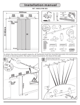
Step 4. Attach the Arm Assembly to the Wall Plate
Step 5. Attaching the Display to the Arm Assembly
A. Loosenthetwoupperclampingscrewsonthearmassembly.
B. Alignthearmassemblywiththetopandbottomrailofthewallplate.
C. Slidethearmassemblyintopositionwhileloweringandpushingittowardthewall.Loosentheupperclamping
bolts more if the assembly will not clip onto the rail.
D. Tightentheupperandlowerclampingboltsusingthesmall4mmAllenwrench(T1).
E. IftheSM-RAZOR-ART1-BKT-20isbeingused,thewallbracketendcoverscannowbeinstalled.
1. Liftthedisplayandplaceitontheendofthearmassemblyas
shown in Figure 10.
2. SecurethedisplayusingthetwoNylonwashers(X),twometal
washers (V), and lock nuts (W). Be sure to place the Nylon
washer between the mount and the metal washer. This will allow
for easier tilt adjustments later.
3. Tightenthenutswiththe8mmsocketwrench(T3).
Figure 8. Figure 9.
Tighten
Screws
Raise Block
Assembly
Tighten
Screws
(X) (V) (W)
Figure 10.

Pg.8
SM-RAZOR-ART1-M Installation Manual
© 2014 Strong
®
6. Adjusting Display Position
6.1. Horizontal Level Adjustments
6.2. Vertical Position Adjustments
1. Loosenthetwolockingnuts(W)atthebottomofthearmassemblyendplateusingthe8mmsocketwrench(T3).
(Figure11)
2. Placealevelontopofthedisplay,androtatethedisplayuntilitishorizontallylevel.(Figure12)
3. Tightenthelockingnutsatthebottomofthearmassemblyendplateandthenloosenthem¼turn.Thiswillallow
for the display to be positioned with minimal effort.
4. Afteradjustmentiscomplete,tightenthenuts.
Theverticalpositionofthedisplaycanbeadjusted+/-3/8”fromthepre-adjustedcenteredposition.Thisisachieved
bytightening(up)orloosening(down)theverticaladjustmentscrewlocatedonthearmplate.
1. Extendthearmtoaccesstheverticalpositionadjustment.
2. Loosenthefourlock-nutsontherearofthearmplateusingthe8mmsocketwrench(T3).(Figure13)
3. UsingtheLarge4mmAllenwrench(T2),tightentheadjustmentscrewtoraisethedisplay,orloosenthescrew
tolowerthedisplay.(Figure14)
4. Tightenthefourlocknutsontherearofthearmplateusingthe8mmsocketwrench(T3).
Figure 11. Figure 12.
Horizontal Level
Adjustment Nuts (W)
+/- 4°
Figure 13. Figure 14.
Lock Nuts
Large 4mm Allen Key (T2)

Pg.9
SM-RAZOR-ART1-M Installation Manual
www.snapav.com Support: 866.838.5052
6.3. Adjusting Home Position (Fully Retracted)
6.4. Tilt Adjustments
The mount includes a home position latch that
secures the arm to the wall mount. This prevents
the display from being pushed away from the wall
due to cabling.
Note: Only theTV Plate side of the latch is pre-
installed. The home position latch clip requires
installation and adjustment.
Tilt adjustments usually do not require loosening
any bolts or screws. The tilt plate fasteners have
been pre-adjusted for easy adjustment with most
TVs.However, heavierTVsmay sag due to the
extra weight.
Ifthisoccurs,evenlytightenthelocknutsoneach
side of the end plate using the small 4mmAllen
Wrench (T1) until the display no longer sags.
(Figure16)
1. Extendthearmoutawayfromthewall.
2. Attach the home position latch (Y) to the
wall arm assembly using the three screws
(Z) as shown in Figure 15. Use a #2 Phillips
screwdriver to adjust the screws.
3. Leavethescrewslooseenoughtobeableto
adjust the latch and set it at the top of its travel.
4. Pushthedisplaybacktothewall.
5. Ifno“click”isheardasthearmispushedat,
adjust the latch downward and test again.
6. Repeatthesestepsuntila“click”isheardandthedisplaylatchescompletelytothewallmount.
7. Afterthelatchissetcorrectly,tightenthescrewscompletely.
Figure 15.
Figure 16.
(Y) x1
(Z) x3
11°
5°
Tilt Adjustment Nuts
(2 per side)

Pg. 10
SM-RAZOR-ART1-M Installation Manual
© 2014 Strong
®
7. Specifications
8. Dimensions
Finish Type PowderCoated,MatteFinish
Product Weight 13.30lbs.
Maximum Display Load 50lbs.(22.67kg)
Minimum Mounting Pattern 100x100VESA
Maximum Mounting Pattern 200x200VESA
Retracted On-Wall Thickness (inches) 1.65”
Maximum Extension (inches) 22.3”
Pan/Swivel Range 180°
Tilt Angle Range -11°,+5°
Certications UL
22. in.
13.94in.
1.71in. 3

Pg. 11
SM-RAZOR-ART1-M Installation Manual
www.snapav.com Support: 866.838.5052
Lifetime Limited Warranty
Strong™MountshaveaLifetimeLimitedWarranty.Thiswarrantyincludespartsandlaborrepairs
on all components found to be defective in material or workmanship under normal conditions of
use.Thiswarrantyshallnotapplytoproductswhichhavebeenabused,modiedordisassembled.
ProductstoberepairedunderthiswarrantymustbereturnedtoSnapAVoradesignatedservice
centerwithpriornoticationandanassignedreturnauthorizationnumber(RA).
Lifetime
Phone: (866)838-5052
Email: Techsupport@snapav.com
9. Warranty
10. Contacting Technical Support

©2014STRONG™
140307-1130
/