
Electric Heater Kits
Installation in Standard and Variable Speed Indoor Air Handlers
H6HK Series
Installation Instructions
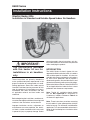
IMPORTANT:
The instructions included
with this heater kit are for
installations in air handlers
only.
These instructions are primarily intended to
assist qualifi ed individuals experienced in the
proper installation of heating and/or air condi-
tioning appliances. Some local codes require
licensed installation/service personnel for this
type of equipment. All installations must be in
accordance with these instructions and with
all applicable national and local codes and
standards.
Before beginning the installation, read these in-
structions thoroughly and follow all warnings and
cautions in the instructions and on the unit.
Improper installation, service, adjustment, or
maintenance can cause explosion, fi re, electri-
cal shock, or other conditions which may result
in personal injury or property damage. Unless
otherwise noted in these instructions, only fac-
tory authorized kits or accessories may be used
when modifying this product.
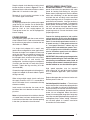
INTRODUCTION
The H6HK Series of electric heater kits are
approved for fi eld installation in B5 air handlers
and variable speed air handlers. All sizes are
available with factory-provided circuit-breakers
for short circuit protection and to provide a
disconnecting means. Also available are 5, 8, and
10 kw electric heater kits without circuit-breakers.
Refer to the National Electric Code (ANSI/NFPA
70) and applicable local codes for over-current
protection and disconnect requirements.
Note: The 20, 25, and 30 kw electric heater
kits are Not Approved for installation in
A-cabinet air handlers. Reference Table 2 for
all Heater Kit applications.
Note: These instructions are written assuming
the air handler is in the upfl ow position (with the
outlet facing up). For horizontal and downfl ow
applications, it is recommended that the electric
heater kit be installed prior to installation of the
air handler.

2
WARNING:
To avoid the risk of electric
shock, personal injury, or death,
disconnect all electrical power
to the unit before performing
any maintenance or service.
The unit may have more than
one electrical power supply.
AIR HANDLER ELECTRICAL
SUPPLY
All wiring must be in compliance with the National
Electric Code and applicable local codes.
If the air handler was previously installed without
electric heat the existing supply wiring may not be
suffi cient to carry the increased load. If installing
electric heat in the B5 air handler the supply
wiring can be aluminum or copper since the
circuit breakers and terminal blocks supplied are
approved for either wire type. Be sure to follow all
of the rating information on the circuit breaker or
terminal block and ensure that the supply wiring
is sized according to the current NEC codes and
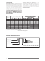
any other state or local codes. See the rating
label or Table 1 for minimum circuit ampacities
and maximum overcurrent protection.
All electric heater kits of 10 kw or less are supplied
from the factory confi gured for use with a single
supply circuit. Electric heater kits greater than 10
kw are supplied from the factory confi gured for
use with two supply circuits. See the ratings label
or Table 1 for individual circuit ampacities and
over-current protection ratings. If a single supply
is desired, accessory kit #913874 is required to
convert to single circuit connection.
INSTALLATION
Remove the upper access door from the air
handler. Remove the circuit breaker bracket and
cover package from the heater kit.
Remove the top-most element Close-off Plate
from the back of the air handler control box.
For two-tiered electric heater kits remove both
Close-off Plates. For three-tiered electric heater
kits remove all three Close-off Plates.
Installation into Air Handler, All Heater Kits
Insert the element assembly into the opening in
the air handler control box being careful not to
damage the element wire or the ceramic element
supports. Heating element alignment rod(s)
will slide into alignment holes in the back of the
air handler element box. Secure the element
assembly to the back of the air handler control
box with the screws removed when removing
the element close-off plate(s).
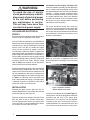
For 25 kw and 30 kw Heater Kits, attach the
Auxiliary circuit board bracket to the lower right
side of the installed Heater Kit Assembly with
two screws that were removed from the element
close-off plate(s). Snap on the Auxiliary circuit
board as shown below.
Figure 1. Sample Installation.
Shown without access door.
Note: on some units a shipping bracket must
be removed before installing the circuit breaker
bracket.
Install the circuit-breaker bracket (See Figure 1).
Connect the 2-Pin Power plug from the element
assembly into the unit's 2-Pin power plug.
Connect the 7-Pin Harness from the element
assembly to the unit's circuit board. For 25 kw
and 30 kw Heater Kits, also attach the 4-Pin and
3-Pin Harnesses to the Auxiliary circuit board.

3
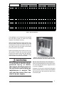
Table 1. Electrical Ratings
A wiring diagram and a ratings label are supplied
with the electric heater kit. Attach the wiring
diagram to the Blower Housing.
When installing the electric heater kit into a stan-
dard air handler, attach the rating label (included
with the electric heater kit) on the air handler unit
data label (located on the lower access door)
over the electrical data section.
When installing the electric heater kit into a vari-
able speed air handler the rating label supplied
with the kit will not be used. Check the appropri-
ate block on the air handler additional ratings
label located on the lower access door.
WARNING:
To avoid risk of electric shock,
personal injury, or death,
disconnect electrical power to
the unit before performing any
maintenance or service. The
unit may have more than one
electric power supply.
Standard Air Handler (A & B size) Variable Speed & Std Air Handler (C size)
Circuit Circuit Circuit Single Circuit Circuit Circuit Single Circuit Circuit Circuit Single Circuit Circuit Circuit Single
ABC
Circuit
ABC
Circuit
ABC
Circuit
ABC
Circuit
005H-XX
240 4.8 - - - 30 - - - 30 - - - 34 - - - 40
008H-XX
240 7.5 - - - 45 - - - 50 - - - 48 - - - 50
010H-XX
240 9.6 - - - 55 - - - 60 - - - 59 - - - 60
015H-XX
240 14.4 55 25 - 80 60 30 - 90 59 25 - 83 60 30 - 90
020H-XX
240 19.2 55 50 - 105 60 60 - 125 59 50 - 109 60 60 - 125
025H-XX
24024.0---- ---- 595025134606030150
030H-XX
24028.8---- ---- 595050159606060175
005H-XX
208 3.6 - - - 27 - - - 30 - - - 30 - - - 40
008H-XX
208 5.6 - - - 39 - - - 40 - - - 42 - - - 50
010H-XX
208 7.2 - - - 48 - - - 50 - - - 52 - - - 60
015H-XX
208 10.8 48 21 - 70 50 25 - 80 52 22 - 73 60 25 - 80
020H-XX
208 14.4 48 43 - 92 50 50 - 100 52 43 - 95 60 50 - 100
025H-XX
20818.0---- ---- 524322117605025125
030H-XX
20821.6---- ---- 524343138605050150
009Q-XX
240 9.0 - - - 32 - - - 40 - - - 36 - - - 40
015Q-XX
240 14.4 - - - 48 - - - 50 - - - 52 - - - 60
009Q-XX
208 6.8 - - - 29 - - - 30 - - - 32 - - - 40
015Q-XX
208 10.8 - - - 43 - - - 50 - - - 46 - - - 50
Max. Over-Min. Circuit
Am
p
acit
y
Max. Over-
Current Protection
Min. Circuit
Am
p
acit
y
Model Number
H6HK- Volta
g
eKW
Current Protection
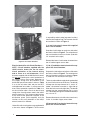
Electric Heater Kits without Circuit Breakers —
Attach the supplied power terminal block to the
circuit-breaker bracket with the supplied screws
as shown in Figure 2.
Using the 1/4" terminals, connect the red supply
wire(s) from the element assembly to one pole of
the terminal block and connect the black wires
to the other pole.
Figure 2. Circuit Breaker Brackets. Shown with
Line Cover Removed and Terminal Block Installed.

4
is required by code in order to protect installers
from the line/supply wiring. The line cover should
be installed as shown in Figure 4.
5, 8, and 10 kw electric heater kits supplied
with a circuit breaker.
Snap the circuit breaker on to the circuit breaker
bracket as shown in Figure 5. The orientation of
the circuit breaker must be as shown. (Side with
1/4" terminals to the right).
Remove the lower circuit breaker knockout from
the air handler upper access door.
15, 20, 25, and 30 kw electric heater kits sup-
plied with circuit breakers.
Snap the circuit breakers on to the circuit breaker
bracket as shown in Figure 5. The orientation of
the circuit breakers must be as shown in Figure
1. (Side with 1/4" terminals to the right).
The heavy red and black supply leads are bundled
by circuit with wire ties at the factory. The bundle
coming from the top element tier is circuit “A”
(note: the element assembly is right-side-up
when the limits are on the right side). The bundle
coming from the second element tier is circuit
“B”. The bundle coming from the bottom element
tier is circuit "C".
Remove all necessary circuit breaker knockouts
in the air handler upper access door.
3-Phase 9 and 15 kw electric heater kits sup-
plied with a circuit breaker.
Figure 5. Installation of Circuit Breakers
Electric Heater Kits with Circuit Breakers —
NOTE : Circuit breakers supplied with the
H6HK electric heater kits are for short-
circuit protection of the internal wiring
and to serve as a unit disconnect. Circuit
breakers supplied with the H6HK electric heater
kits do not provide over-current protection of
the supply wiring. Over-current protection of
the supply wiring must be provided at the
distribution panel and sized as shown in Table
1 or on the unit data label and per the NEC
and applicable local codes. In some cases the
over-current protection specifi ed in Table 1 or
on the unit data label is less than the 60 amp
rating of the circuit breakers used in the H6HK
electric heater kits. This is because the function
of the over-current protection required at the
distribution panel (field supplied) and the
function of the circuit breakers in the H6HK
electric heater kit is different.
Heater Kits with circuit breakers are supplied with
a line cover shown in Figure 3. The line cover
Figure 3. Line Cover
Figure 4. Line Cover Installed

5
Snap the 3-pole circuit breaker on to the circuit
breaker bracket as shown in Figure 5. The ori-
entation of the circuit breaker must be as shown.
(Side with 1/4" terminals to the right).
Remove all circuit breaker knockouts in the
air handler upper access door.
STAGING
All Single-phase heater kits are internally staged
using the B5 Air Handler Circuit Board logic.
Reference B5 Air Handler Installation Instruc-
tions for "slow" or "fast" staging options. All
Three-phase heater kits are not equipped for
internal staging.
POWER WIRING
All wiring must comply with the current revision
of the National Electric Code and must be sized
for the minimum ampacities as listed on the unit
data label or in Table 1.
If a single circuit adaptor kit is used it may
need to be re-confi gured for some applications.
Remove the single circuit adaptor kit cover and
verify that the lugs are confi gured correctly for
the application. If the lugs are not confi gured
for the application, reference the instructions
included with the kit and modify the
confi guration. Install the single circuit adaptor kit
(if used) in the line side (“on” end) of the circuit
breakers. Tighten the lugs securely (45 in-lbs
recommended).
Connect the supply wiring to the circuit breaker(s),
single circuit adaptor kit, or terminal block. Tighten
the lugs securely.
When using multiple supply circuits verify that
the supply sized for circuit “A” is connected to
the circuit breaker that is connected to the top
element assembly.
Install metal circuit breaker line cover on the
left side of the circuit breaker to cover the sup-
ply wires.
Note; on 3-phase heater kit installations after the
air handler door has been attached to the unit,
install the circuit breaker close-off to the opening
in the door just above the circuit breaker.
MOTOR SPEED SELECTION
Standard Air Handlers — The blower speed is
preset at the factory for operation at the same
speed for heating and cooling, by using the
blower motor jumpering terminal on the blower
motor and connecting it to the desired speed
with both the red and black wires connected
to the jumpering terminal. For optimum system
performance and comfort, it may be necessary
to change the factory set speed. To change the
blower speed, disconnect all electrical power to
the unit and remove the upper door. Remove
the black and red wires from the blower motor
jumpering terminal. Discard the blower motor
jumpering terminal.
Connect the heating speed wire (red) and the
cooling speed wire (black) to the desired blower
speed marked on the terminal block of the blower
motor. On standard 3 speed motors terminal 4 =
Hi speed, terminal 5 = Med speed and terminal
6 = Low speed. Standard C cabinet units are
equipped with 5 selectable blower speeds. Termi-
nal 1=Low speed, terminal 2=Medium Low speed,
terminal 3=Medium speed, terminal 4=Medium
Hi speed and terminal 5=Hi speed.
IMPORTANT: After making any changes to the
blower speed setting be sure to bundle and
insulate any unused blower motor leads so
that they will not come in contact with the air
handler cabinet or non-insulated live parts.
High speed operation may be required
when using a 20, 25, and 30 kw electric heater
kit in a downfl ow application. (See Clearance
section.)
Replace the upper door and secure it to the unit.
Restore power to the unit.
Variable Speed Air Handlers — The minimum
electric heat airfl ow is selected by setting switches
on the air handler circuit board. Selecting the
minimum electric heat airfl ow sets the minimum
air fl ow that will be produced whenever electric
heater kits are energized. When the electric
heater kits are energized along with a heat pump
the airfl ow may be higher depending on the basic
cooling/heat-pump airfl ow setting. Reference
the variable speed air handler installation
instructions for further details.

6
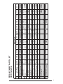
Table 2. Blower Heating Speed
MODEL IDENTIFICATION
Product Type
H - Heater
Generation
6 - Sixth Series
Product Identifi er
HK - Heater Kit
H6 H K - 020 H - 2 1
Staging
Circuit Breakers
Electrical Code
H : 240 - 1 - 60 Q : 208/240 - 3 - 60
Primary Capacity
005 - 5kw 009 - 9kw 015 - 15kw 025 - 25kw
008 - 8kw 010 - 10kw 020 - 20kw 030 - 30kw
(1) Only on *30 (2.5 Ton) model air handlers
Model
H6HK
Applicable Cabinet Size
Minimum Required Blower
Heating Speed
A B C Up-Flow Horizontal Down-Flow
005H
X X X LOW LOW LOW
008H
X X X LOW LOW LOW
010H
X X X LOW LOW LOW
015H
X X X LOW LOW MED
020H
X X LOW LOW HIGH
025H
X X MED MED HIGH
030H
X MED MED N/A
009Q
X X LOW LOW LOW
015Q
X X LOW LOW MED
(1)*
CLEARANCE
Standard Air Handlers — All electric heater kits
less than 20 kw are approved for use in air handler
installations with zero-clearance to combustibles
at any blower speed. For horizontal and upfl ow
confi guration, air handlers equipped with 20, 25,
and 30 kw electric heater kits are approved for
installation with zero clearance to combustibles
at any blower speed. When using a 20, 25 kw
electric heat kit in a downfl ow installation, the
blower MUST be set for high speed for both
heating and cooling.
Variable Speed Air Handlers — All
installations of H6HK electric heater kits in
variable speed air handlers are approved for
zero-clearance to combustibles when the
minimum electric heat airfl ow is set as directed
in these instructions.

7
Model H6HK
No.
Component
Description
005H-01 005H-11 008H-01 008H-11 009Q-11 010H-01 010H-11 015H-21 015Q-11 020H-21 025H-31 030H-31
1 Set of Wires 288351R 288351R 288361R 288361R 291531R 288361R 288361R 288371R 291531R 288381R 289011R 288391R
2 Harness, Low Voltage 634664 634664 634665 634665 634665 634665 634665 634666 634665 634667 634668 634668
3
Element Assy 491214R 491214R 491226R 491226R 491216R 491225R 491225R 491214R 491214R 491225R 491214R 491225R
Element Assy 491227R 491225R 491225R 491225R
4 Relay 622210 622210 622210 622210 622210 622210 622210 622210 622210 622210 622210 622210
5
Limit Switch 626487 626487 626458 626458 626458 626458 626458 626458 626458 626458 626458 626458
Limit Switch 626487 626487
6 Terminal Block 631762 631762 631762
7 Line Cover 257442 257442 257442 257442 257442 257442 257442 257442 257442 257442 257443 257443
8 Bracket, Circuit Breaker 284861 284861 284861 284861 284861 284861 284861 284861 284861 284861 284862 284862
9 Circuit Breaker 632249 632249 632225 632249 632249 632225 632249 632249 632249
10 Harness, 2 Pin Power 288861R 288861R 288861R 288861R 288861R 288861R 288861R 288861R 288861R 288861R
11 Harness, 3 Pin 634670 634671
12 Bracket, Circuit Board 289841 289841
13 Circuit Board 624664 624664
14 Contactor 621888 621888
15 Relay Bracket 288621 288621 288621 288621 288621 288621 288621 288621 288621 288621 288621 288621
16 Cover Plate, Limit hole 292211 292211
REPLACEMENT PARTS LIST
H6HK Heater Kits

8
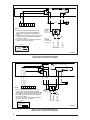
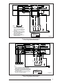
Figure 5. Typical System Wiring Diagram
H6HK, 8/10 kw 1-stage with circuit breaker
GREY
GREY
BLUE
ORANGE
12
3
4
5
6
7
POWER
LIMIT
RED
RED
RED
BLACK
BLACK
RED
BLACK
RELAY
RELAY
TERMINAL
BLOCK
(for select
models only)
CIRCUIT
BREAKER
Legend
Field Wiring
Factory Wiring:
Low Voltage
High Voltage
NOTES
1) If any of the original wire supplied with this unit
must be replaced, it must be replaced with wiring
material of the same gauge size and temperature rating.
2) The installation of this heater kit may require a change
in the blower speed tap connection. See Installation
Instructions for details.
3) Use copper conductors with a minimum temperature
rating of 60°C for supply connections.
ELEMENT
BLACK
BLACK
ELEMENT
RED
710561A
Figure 4. Typical System Wiring Diagram
H6HK, 5 kw 1-stage with circuit breaker
TERMINAL
BLOCK
(for select
models only)
CIRCUIT
BREAKER
(Circuit breaker
models only)
Legend
Field Wiring
Factory Wiring:
Low Voltage
High Voltage
RELAY
GREY
ORANGE
BLACK
RED
RED
LIMIT
POWER
BLACK
1
2
3
4
5
6
7
NOTES
1) If any of the original wire supplied with this unit
must be replaced, it must be replaced with wiring
material of the same gauge size and temperature
rating.
2) The installation of this heater kit may require a change
in the blower speed tap connection. See Installation
Instructions for details.
3) Use copper conductors with a minimum temperature
rating of 60°C for supply connections.
BLACK
RED
ELEMENT
710560A

9
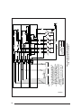
Figure 7. Typical System Wiring Diagram
20 kw 1-stage with circuit breakers
POWER
Legend
Field Wiring
Factory Wiring:
Low Voltage
High Voltage
NOTES
1) If any of the original wire supplied with this unit
must be replaced, it must be replaced with wiring
material of the same gauge size and temperature rating.
2) The installation of this heater kit may require a change
in the blower speed tap connection. See Installation
Instructions for details.
3) Use copper conductors with a minimum temperature
rating of 60°C for supply connections.
CIRCUIT
BREAKERS
SUPPLY VOLTAGE
GROUND
GREY
ORANGE
BLUE
YELLOW
RELAY
RELAY
RELAY
ELEMENT
LIMIT
BLACK
BLACK
BLACK
RED
RED
BLACK
BLACK
BLACK
ELEMENT
ELEMENT
RED
RED
RED
RED
RELAY
BROWN
ELEMENT
BLACK
LIMIT
RED
RED
1
23
4
5
67
RED
BLACK
Figure 6. Typical System Wiring Diagram
15 kw 1-stage with circuit breakers
CIRCUIT
BREAKERS
SUPPLY VOLTAGE
GROUND
1
23
4
5
67
POWER
GREY
ORANGE
BLUE
YELLOW
RELAY
RELAY
RELAY
ELEMENT
LIMIT
LIMIT
RED
BLACK
BLACK
Legend
Field Wiring
Factory Wiring:
Low Voltage
High Voltage
BLACK
RED
RED
RED
BLACK
RED
BLACK
BLACK
BLACK
ELEMENT
ELEMENT
NOTES
1) If any of the original wire supplied
with this unit must be replaced, it
must be replaced with wiring material
of the same gauge size and tempera-
ture rating.
2) The installation of this heater kit may
require a change in the blower speed
tap connection. See Installation
Instructions for details.
3) Use copper conductors with a
minimum temperature rating of 60°C
for supply connections.
RED
RED
710563A
710564A

10
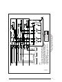
Figure 8. Typical System Wiring Diagram
25 kw 1-stage with circuit breakers
CIRCUIT
BREAKERS
SUPPLY VOLTAGE
GROUND
1
23
4
5
67 1
2
3
4
12
3
POWER
RED
BLACK
GREY
ORANGE
BLUE
YELLOW
YELLOW
BROWN
BROWN
WHITE
GREY
RELAY
RELAY
RELAY
RELAY
RELAY
LIMIT
LIMIT
LIMIT
RED
RED
BLACK
BLACK
Legend
Field Wiring
Factory Wiring:
Low Voltage
High Voltage
BLACK
BLACK
RED
RED
BLACK
RED
RED
RED
RED
RED
NOTES
1) If any of the original wire supplied with
this unit must be replaced, it must be
replaced with wiring material of the
same gauge size and temperature rating.
2) The installation of this heater kit may
require a change in the blower speed tap
connection. See Installation Instructions
for details.
3) Use copper conductors with a minimum
temperature rating of 60°C for supply
connections.
ELEMENT
ELEMENT
ELEMENT
ELEMENT
ELEMENT
BLACK
BLACK
BLACK
BLACK
RED
RED
BLACK
BLACK
710565A

11
Figure 9. Typical System Wiring Diagram
30 kw 1-stage with circuit breaker
CIRCUIT
BREAKERS
SUPPLY VOLTAGE
GROUND
1
23
4
5
67 1
2
3
4
12
3
POWER
RED
BLACK
GREY
ORANGE
BLUE
YELLOW
YELLOW
BROWN
BROWN
WHITE
GREY
RELAY
RELAY
RELAY
RELAY
RELAY
LIMIT
LIMIT
LIMIT
RED
RED
BLACK
BLACK
Legend
Field Wiring
Factory Wiring:
Low Voltage
High Voltage
BLACK
BLACK
RED
RED
BLACK
RED
RED
NOTES
1) If any of the original wire supplied with this unit
must be replaced, it must be replaced with wiring
material of the same gauge size and temperature rating.
2) The installation of this heater kit may require a change
in the blower speed tap connection. See Installation
Instructions for details.
3) Use copper conductors with a minimum temperature
rating of 60°C for supply connections.
Y
RELAY
RED
RED
RED
RED
RED
RED
RED
BLACK
VIOLET
BLACK
BLACK
BLACK
BLACK
BLACK
ELEMENT
ELEMENT
ELEMENT
ELEMENT
ELEMENT
ELEMENT
BLACK
BLACK
BLACK
BLACK
BLACK
710566A

Specifi cations and illustrations subject to
change without notice and without incurring
obligations.
Printed in U.S.A. (09/06)
708514B (Replaces 708514A)
INSTALLER: PLEASE LEAVE THESE INSTALLATION
INSTRUCTIONS WITH THE HOMEOWNER
¢708514%¤
708514B
CIRCUIT
BREAKERS
SUPPLY
VOLTAGE
GROUND
POWER
PLUG
LIMIT
Legend
Field Wiring
Factory Wiring:
Low Voltage
High Voltage
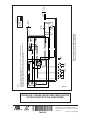
NOTES
1) The blower motor speed tap connection may not be as shown. See the Installation Instructions.
2) Disconnect all power before servicing.
3) Transformer may have a dual voltage primary tap. Match the tap position with the supply voltage used.
4) If the Internal wiring is replaced, use only 105
°C copper wire of the same gauge.
TRANSFORMER
24V
BLACK
WHITE RED
GREY
HEATER KIT
PLUG
2
1
BLACK
RED
ELEMENT 1
BLACK
L1
L2
L3
L1
L2
L3
ELEMENT 2
ELEMENT 3
BLACK
YELLOW
RED
BLACK
RED
BLACK
YELLOW
RED
ELEMENT 3
ELEMENT 2
ELEMENT 1
CONTACTOR
BLACK
34
56
7
RELAY
RED
ORANGE
GREY
From indoor
air handler
circuit board
RED
GREY
From indoor
air handler
circuit board
To indoor
air handler
circuit board
COM
NO
YELLOW
BLACK
BROWN
7105670
Figure 10. Typical System Wiring Diagram
9kw and 15kw 3-phase electric heater kit
-
 1
1
-
 2
2
-
 3
3
-
 4
4
-
 5
5
-
 6
6
-
 7
7
-
 8
8
-
 9
9
-
 10
10
-
 11
11
-
 12
12


Maytag H6HK, 30 Kw 240V,1-Phase Electric Heater Kit Installation guide
- Type
- Installation guide
Ask a question and I''ll find the answer in the document
Finding information in a document is now easier with AI
Related papers
-
Intertherm H3HK Large Package Electric Heater Kit (includes Wiring Diagrams) Product information
-
Broan H6HK Electric Heater Kit Installation guide
-
Broan PAH2BM Product information
-
Broan H6HK, 8, 10 Kw 240V,1-Phase Electric Heater Kit Product information
-
-
Broan H4HK, 208/240V, 3-Phase Electric Heater Kit - A or B Series Product information
-
Westinghouse H3HK Product information
-
-
-
Other documents
-
Unbranded H3HK Small Package Electric Heater Kit (includes Wiring Diagrams) Product information
-
-
-
-
Broan H3HK Small Package Electric Heater Kit (includes Wiring Diagrams) Product information
-
Gibson GB5BM Product information
-
Nordyne H6HK-009Q Installation and Operation Manual
-
-
-