Page is loading ...

Triode Electronics
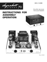
ST70 Kit
INSRUCTION MANUAL
Rev. 1 2007

Step 1: Mount the power transformer into the chassis using 8-32locknut
Step 2: Mount Rubber grommets for output transformer leads

Step 3: Mount Rubber grommets for other output transformer and install C354 choke using 6-32 bolts and
locknuts
Step 4: Mount output transformers into chassis using 8-32 bolts and lock washers, run leads through
grommet holes into chassis.

Step 5: Mount Octal sockets for EL34 tubes and 5AR4 tube into chassis using 4-40 bolts and nuts
Step 6: Install 10k bias potentiometers into chassis

Step 7: Install bias test points next to bias potentiometers
Step 8: Install power switch into back panel of chassis

Step 9: Install Gold Insulated RCA Jacks into the front panel of the chassis:

Step 10: Build and Install the Driver PCB board into the chassis
A. populate resistors onto board
B. Populate Polystyrene Capacitors onto board

C. Populate Coupling Capacitors and Screen Bypass Caps onto board
D. Solder PC mount sockets onto the board
E. Install Built driver board into chassis using 4-40 bolts and nuts

Step 11: While we’re at it lets go ahead and put together the SDS Labs capacitor board so it will be ready
for later
A. Install Snap in Capacitors into the board and solder in place
B. Install Resistors on top side of board

C. Install Bias caps, Heater bypass caps, and bias supply diode
D. Install surface mount resistors onto the bottom of the board

Step 12: Let the wiring begin, lets first twist wires from the power transformer together. Twist the
following wires together: the two green wires, the two brown wires, the two white wires, and the two red
wires.
Step 13: Now twist the wires from the output transformers: twist the blue and green wires together, twist
blue/white and green/white wires together.

Step 14: Wire the twisted Red leads from the power transformer to pins 4 & 6 of the 5AR4 socket
Step 15: Wire the twisted white leads from power transformer to pins 2 & 8 of the 5AR4 socket

Step 17: Wire the Blue/White & Green/White wires of both output transformers to pins 3 & 4 of the EL34
sockets that are closest to the back of the chassis. Blue/White goes to pin 3 and Green/White to pin 4

Step 18: Wire the Blue and Green wires from the output transformers to pins 3 & 4 of the other EL34
sockets that are closest to the front of the chassis. The blue wire connects to pin 3 and the Green wire
connects to pin 4.

Step 19: Solder 1k grid stopper resistors onto all EL34 sockets. Resistors are installed between pins 5 & 6.

Step 20: Wire Eyelet #6 of the driver board to the center lug of the right bias pot (looking from bottom of
amp). Also wire Eyelet # 2 to pin 6 of The EL34 with the blue/green wires going to it and Eyelet #1 to pin 6
of the EL34 with the Blue/White and Green/White wires going to it.

Step #21 Repeat this procedure for the other side of the amplifier, Connect eyelet #21 to center lug of left
bias pot (looking from bottom of amp). Also connect eyelet # 23 to pin 6 of EL34 with the blue/green wires
going to it and eyelet # 22 to pin 6 of the EL34 with the blue/white and green/white wires going to it.

Step 22: install solder lug onto 4-40 bolt/nut that holds on one of the EL34 sockets on each side. Take the
10ohm resistor and connect it to pins 1 & 8 of the EL34 socket to the solder lug. Then take a wire off either
pin 1 or 8 and connect it to pins 1 & 8 of the other EL34 on that side. Do this on both sides of the amplifier.

Step 23: Now we will begin wiring the SDS Labs capacitor board into the circuit
A. Connect a wire from pin 8 of the 5AR4 socket to one of the eyelets on the cap board labeled Rcath/Ind1.
Also wire one wire from the C354 choke to the same eyelets.
B. Connect the other wire from the C354 choke to one of the eyelets on the cap board labeled Ind2/Out.
Also wire the red leads from the A470 output transformers to these same eyelets.
C. Connect a wire from the eyelet labeled Eye20, this wire will be connecting to eyelet 20 on the Driver
PCB board so make sure you have enough length.
D. Connect a wire from the eyelet labeled Eye19, this wire will be connecting to eyelet 19 on the Driver
PCB board so make sure you have enough length.
E. Connect the red/black wire from the PA060 power transformer to the eyelet right after the diode on the
board labeled C-.
F. Connect a wire from the right bias pot’s right terminal (looking at amp from bottom) to the next eyelet
after C-
G. Connect a wire from the right bias pots’s left terminal (looking at amp from the bottom) to the last eyelet
on the board .
H. Connect the Green/Yellow wire and Brown/Yellow wire from the PA060 power transformer to the
eyelets marked FCT.
J. Connect a wire to one of the three unlabelled eyelets on the side of the board by the FCT eyelets, this
wire will be going to our main chassis ground point so make sure you leave enough length.

Note: on this picture one of the A470’s red wires is not connected to the board and the main ground wire is
not yet attached.
/