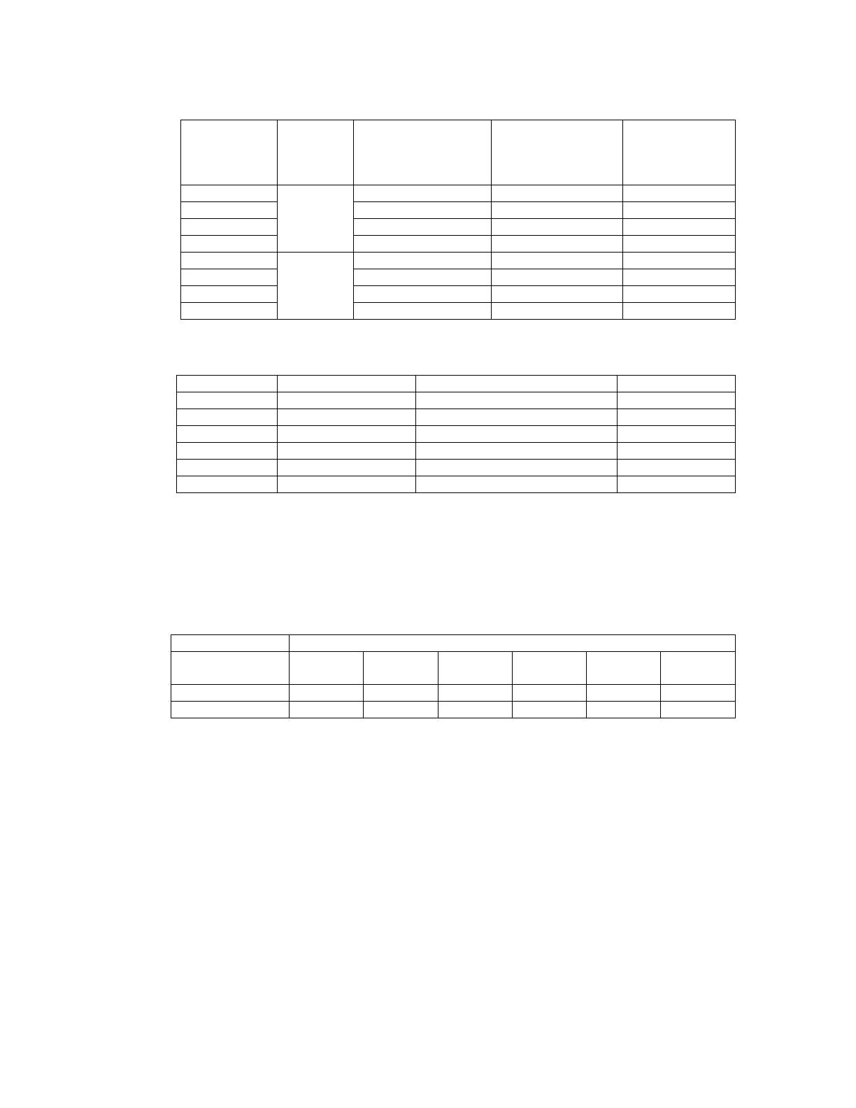
Victron energy PowerManager Owner's manual

Type
Owner's manual

Victron energy PowerManager is a device designed to manage and optimize the use of multiple AC power sources, such as generators and shore power, in parallel with Victron Multi or MultiPlus inverters. It enables seamless switching between AC sources, provides generator power limiting, and facilitates the PowerControl and PowerAssist functions of the inverters. With PowerManager, you can configure your system to prioritize generator power, set AC current limits, and automatically reduce battery charging current when AC power is limited.

Victron energy PowerManager is a device designed to manage and optimize the use of multiple AC power sources, such as generators and shore power, in parallel with Victron Multi or MultiPlus inverters. It enables seamless switching between AC sources, provides generator power limiting, and facilitates the PowerControl and PowerAssist functions of the inverters. With PowerManager, you can configure your system to prioritize generator power, set AC current limits, and automatically reduce battery charging current when AC power is limited.

INSTALLATION MANUAL
PowerMan
230/40-1
230/80-1
230/40-2
230/80-2
Victron Energy B.V. / De Paal 35 / 1351 JG ALMERE / The Netherlands
Phone: (+31) (0)36 535 97 00 / Fax: (+31) (0)36 535 97 40 / www.victronenergy.com
/ e-mail: sales@victronenergy.com
11/6/2003 1
1. Introduction
The AC input of a Phoenix Multi is fitted with a 16 Amp thermal circuit breaker and a safety relay
(see figure).
When no AC input is available the safety relay will open.
The safety relay is rated at 16 A. The maximum input current of 2 paralleled Multi’s is therefore
32 A. Due to tolerances in relay switching time, the maximum input current of sets of 3 or more
paralleled Multi’s is also limited to 48 A.
Three PowerMan models:
Type 0 is a simple transfer switch for general use.
Type 1 and 2 have been developed specifically for use with the Multi/MultiPlus when more AC
current is required. The PowerControl en PowerAssist functions remain functional.
For more details and examples of PowerAssist, please read Achieving the Impossible”, which
can be found on our website under “The MultiPlus explained”.
PowerMan type 0 (230/40-0 and 230/80-0 )
A simple “break before make” transfer switch with generator priority and a 1 minute transfer
delay.
11/6/2003 2
PowerMan type 1 (230/40-1 and 230/80-1)
Type 1 is intended to operate one or more Multi’s in parallel with 1 AC power source, but without
the input current limitation as mentioned above. The AC current limit (which is the current limit at
which PowerControl and PowerAssist will be activated) can be set at up to 40 A, respectively up
to 80 A, with a potentiometer in the PowerMan box.
PowerMan serie 2 (bijv. 230/40-2 en 230/80-2)
With type 2 one or more Multi’s can operate in parallel with 2 alternative AC power sources. In
general one of the power sources is a generator, and the other shoreside power.
The AC current limit of the generator can be set at up to 40 A, respectively up to 80 A, with a
potentiometer in the PowerMan box.
Two external PowerMan Control panels are available to limit shore current to max. 16 A
respectively 30 A. The external PowerMan Control panels look very similar to the Phoenix
Multi Control Panels but are not interchangeable!
The 40 A model has 3 circuit breakers to connect up to 3 Multi’s. The 80 A model has 5 circuit
breakers to connect up to 5 Multi’s.
Three phase versions are available at request.
11/6/2003 3
2. The parameters to configure a PowerMan
type 1 or 2
Three parameters are of importance to configure a PowerMan type 1 or type 2:
1. The number of Multi’s that will be connected
2. The maximum output current of the generator
3. The maximum shore current (not applicable to PowerMan type 1)
The tables in the next paragraph are a help to determine the configuration parameters.
Paragraph 3 describes how to perform the configuration itself.
2.1. PowerAssist is not required
If the PowerAssist feature is not required, the MultiPlus is not needed and one or more
Phoenix Multi’s can be used.
The PowerControl function (automatic reduction of charge current as soon as the AC
current limit setpoint is reached) will be available.
The configuration parameters can be determined from the following tables:
Max AC
current
required
PowerMan Configuration Contactor
K3
Cable to L-
Out of Master
Bridge
40 A 230/40-1
230/40-2
C Terminal 6 Terminal 3 Terminal 1-2
80 A 230/80-1
230/80-2
F Terminal 2 Terminal 3 Terminal 1-2
The PowerMan Contol Panel is applicable to the PowerMan type 2 only. The following
table should be disregarded when a PowerMan type 1 is used.
Configuration of PowerMan Control Panel
Max shore current C F
16 A 49,9 kOhm 124 kOhm
32 A 12,4 kOhm 49,9 kOhm
2.2. PowerAssist is required
For PowerAssist at least one MultiPlus is needed. If paralleled with one or more Multi’s,
the MultiPlus must be the master.
The configuration parameters can be determined from the following tables:
The configuration can be determined from the first table. The second table relates the
configuration to the implementation as described in paragraph 3.
11/6/2003 4
Number of
paralleled
Multi’s
PowerMan Minimum generator
current/power
required
Maximum
generator
current/power
Configuration
1 10 A / 2,3 kVA 30 A / 6,9 kVA A
2 20 A / 4,6 kVA 37,5 A / 8,6 kVA B
3 30 A / 6,9 kVA 40 A / 9,2 kVA C
4
230/40-1
230/40-2
40 A / 9,2 kVA 40 A / 9,2 kVA D
2 20 A / 4,6 kVA 60 A / 13,8 kVA D
3 30 A / 6,9 kVA 80 A / 18,4 kVA E
4 40 A / 9,2 kVA 80 A / 18,4 kVA F
5
230/80-1
230/80-2
50 A / 11,5 kVA 80 A / 18,4 kVA F
Configuration of the PowerMan:
Configuration Contactor K3 Cable to L-Out of Master Bridge
A Terminal 6 Terminal 1 Terminal 2 - 3
B Terminal 6 Terminal 2 n. a.
C Terminal 6 Terminal 3 Terminal 1 - 2
D Terminal 2 Terminal 1 Terminal 2 - 3
E Terminal 2 Terminal 2 n. a.
F Terminal 2 Terminal 3 Terminal 1 - 2
The PowerMan Contol Panel is applicable to the PowerMan type 2 only. The following
table should be disregarded when a PowerMan type 1 is used.
Configuration of PowerMan Control Panel
Max shore
current
A B C D E F
16 A
24,8 kOhm 37,4 kOhm 49,9 kOhm 75 kOhm 100 kOhm 124 kOhm
32 A
n. a. 6,2 kOhm 12,4 kOhm 24,8 kOhm 37,4 kOhm 49,9 kOhm
11/6/2003 5
3. Implementing the configuration
3.1. Contactor K3
The black cable should be connected to terminal 6 or terminal 2 of contactor K3
(see picture)
cable connected to terminal 6 cable connected to terminal 2
3.2. Bridge
Confuration A and D: interconnection between terminal 2 and 3, see picture.
Confuration C and F: interconnection between terminal 1 and 2.
Confuration B en E no interconnection needed.
11/6/2003 6
3.3. Cable to L-Out of Master
The L-out (=live out) terminal of the Multi or MultiPlus which will be the master must
be connected to terminal 1, 2 or 3 of the PowerMan (see table in paragraph 2.1. or
2.2.). This cable carries the AC current signal to the Multi. The cable must have a
cross section of at least 6
mm² and it should not be longer than 10 meter.
This same L-out terminal must also be connected to one of the circuit breakers in the
PowerMan cubicle. The 2 cables must be crimped together to fit in that same
terminal.
3.4. Removing 2 cable bridges from the Multi’s
The 2 cable bridges with Faston terminals (see left picture) must be removed from all
paralleled Multi’s (from the master and from the slaves).
Then a connection must be made from the the Faston blades J30 en J31 from the
master only to terminal 30 respectively 31 in the PowerMan.
Cable cross section: 2,5 mm².
J30 and J31 to be
connected respectively
to terminal 30 and 31
in the PowerMan
Standard Multi with the 2 bridges
fitted
11/6/2003 7
3.5. The PowerMan Control panel
A resistor (see table in paragraph 2.1 or 2.2) must be placed in the blue
connector on the back side of the PowerMan control panel.
(In case of for example configuration E and 16 A shore current, a 100 kOhm
resistor must be placed)
11/6/2003 8
3.6. Commissioning the PowerMan
We recommend to use our software VE Configure to set the parameters of the
Multi/Multplus which will be used as master. The slaves will automatically follow the
master.
Do not forget to check and set the battery charge parameters.
For the proper functioning of PowerMan type 1 en 2 the internal potentiometer must
be set at the right current.
The purpose is to activate PowerControl and, if required, PowerAssist just before the
generator is overloaded. This is achieved by running the generator, increase the load
to the required maximum current and then turn the internal potentiometer counter
clock wise until the Multi’s start reducing the charge current or, if the charge current is
negligible, start to assist the generator.
Please note that small 3000 rpm gensets of certain brands will overheat when
operating for long periods at full load. In some cases the maximum current will have
to set at no more than 70 % of the rated maximum current.
The current limit of 1500 rpm gensets can in general be set at around 90 % or more
of the rated output current.
  • Page 1 1
  • Page 2 2
  • Page 3 3
  • Page 4 4
  • Page 5 5
  • Page 6 6
  • Page 7 7
  • Page 8 8
  • Page 9 9
  • Page 10 10
  • Page 11 11
  • Page 12 12

Victron energy PowerManager Owner's manual

Type
Owner's manual

Victron energy PowerManager is a device designed to manage and optimize the use of multiple AC power sources, such as generators and shore power, in parallel with Victron Multi or MultiPlus inverters. It enables seamless switching between AC sources, provides generator power limiting, and facilitates the PowerControl and PowerAssist functions of the inverters. With PowerManager, you can configure your system to prioritize generator power, set AC current limits, and automatically reduce battery charging current when AC power is limited.

Ask a question and I''ll find the answer in the document

Finding information in a document is now easier with AI