Page is loading ...

FOR FUTURE REFERENCE
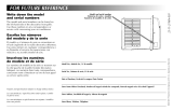
Write down the model
and serial numbers
You’ll find them on a label behind the air dis-
charge grill. Use these numbers in any
correspondence or service calls concerning
your air conditioner.
Escriba los números
del modelo y de la serie
Los encontrará en una etiqueta detrás de la
parrilla de descarga de aire. Utilice estos números
en cualquier correspondencia o llamada de servi-
cio referente a su acondicionador de aire.
Inscrivez les numéros
de modèle et de série
Vous les trouverez sur une étiquette qui se trouve
derrière la grille de sortie d’air. Rappelez ces
numéros dans tout courrier ou appel pour inter-
vention concernant le climatiseur.
Model No., Modelo No., N° de modèle
Serial No., Número de serie, N° de série
Date of Purchase, Fecha de la compra, Date d’achat
Store Name Where Purchased, Nombre del negocio donde fue comprado, Nom du magasin où a été acheté l’appareil
Store Address, Localidad del negocio, Adresse du magasin
Store Phone, Teléfono, Téléphone
Inlet grill
Parrilla de entrada
Grille d’entrée d’air
Model and serial number
Números de serie y modelo
Numéros de modèle et de série
Features and specifications subject to change without notice.
Las características y especificaciones están sujetas a cambio sin
previo aviso.
Les caractéristiques et spécifications sont sujettes à modifica-
tions sans préavis.
©MCMXCIX 9910 Printed in USA, Impreso en EE. UU., Imprimé aux États-Unis
23-11-2103N-003

INSTALLATION & OPERATIONS MANUAL
Including Service and Warranty
Incluidos mantenimiento y la garantía
Avec service et garantie
5,000 – 10,000 BTU’S
Room Air Conditioners for Slider & Casement Windows
Acondicionadores de aire ambiental para ventanas correderas y batientes
Climatiseurs individuels pour fenêtres à glissière et à battants

CONTENTS
Electrical Requirements......2
Warning
Notice
Important Grounding Requirements
Installation...........................2
Window Requirements
Tools Needed
Sliding Window Installation
Casement Window Installation
Installation in Wood Sliding or
Wood Casement Windows
Operation.............................6
Control Functions
Cooling Operation
Air Circulation Without Cooling
Exhaust Operation Without Cooling
Directing Airflow
Cleaning Air Filter
Service.................................8
Insufficient Cooling
Unit Fails To Start
Service or Parts Required
Warranty...............................8
Requistos para
la eléctricos.......................10
Aviso
Aviso
Requistos importantes para la conexión a tierra
Instalación.........................10
Requisitos de la ventana
Herramientas necesarias
Instalación en ventana corrediza
Instalación en ventana de hoja batiente
Instalación en ventanas de hoja batiente
de madera corrediza
Funcionamiento.................14
Funciones de los controles
Funcionamiento del enfriamiento
Circulación de aire sin enfriamiento
Funcionamiento de ventilación sin enfriamiento
Orientación de la corriente de aire
Limpieza del filtro de aire
Servicio..............................16
Enfriamiento insuficiente
Si la unidad no se enciende
Necesidad de servicio o piezas
Garantía.............................16
Exigences électrique.........18
Avertissement
Avis
Importantes exigences de mise à la terre
Montage.............................18
Caractéristiques des fenêtres
Outils nécessaires
Montage dans une fenêtre coulissante
Montage dans une fenêtre à battants
Montage dans des fenêtre à battants en bois ou
coulissantes en bois
Fonctionnement.................22
Fonctions de commande
Refroidissement
Circulation d’air sans refroidissement
Sortie d’air sans refroidissement
Orientation de l’air
Nettoyage du filtre à air
Service...............................24
Refroidissement insuffisant
L’appareil ne se met pas en marche
Réparations ou pièces s’avèrent nécessaires
Garantie.............................24
1
ENGLISH ESPAÑOL FRANÇAIS

Window Requirements
Your new room air conditioner is factory prepared
for easy installation in a horizontal sliding or case-
ment type window with a minimum width of 15
1/2 inches. Unit will fit a 42 inch high window
opening as received from factory.
Caution: Do not block air circulation to outside louvers
of cabinet.
Tools Needed
p
Blade-type screwdriver
p
Ruler
p
Drill
p
Awl
p
1/8 inch drill bit
p
Knife
p
Level
p
Pencil
Important
Grounding Requirements
1. Air conditioner has a three-prong grounding
plug on power supply cord, which must be
plugged into properly grounded three-prong
wall receptacle for your protection against
possible shock hazard. For models up to and
including 7.5 amperes use grounding type
wall receptacle to match cord plug (Fig. 1).
2. For models above 7.5 amperes use single
outlet grounding type wall receptacle to
match cord plug (Fig. 2).
Caution: We recommend that a qualified electrician
install unit in accordance with the National Electrical
Code and local codes and ordinances.
Caution: Use copper conductors only.
INSTALLATION
Three-prong
grounding plug
Single outlet
grounding
wall receptacle
Grounded
three-prong
wall receptacle
1 2
1. ELECTRICAL REQUIREMENTS
WARNING
Electrical Shock Hazard
1. Plug unit only into grounded electrical outlet.
2. Do not use an extension cord or plug adaptor with
this unit.
3. Do not operate unit with front removed.
Failure to follow the above precautions could result in electrical
shock, fire or personal injury.
If the air conditioner has a serial plate rating of 115 volts
and up to and including 7.5 amps the unit may be on a fuse
or circuit breaker with other devices.
However, the maximum
amps of all devices on that fuse or circuit breaker can not
exceed the amps of the fuse or circuit breaker.
If the air conditioner has a serial plate rating of 115 volts
and greater than 7.5 amps it must have its own fuse or cir-
cuit breaker, and no other device or unit should be operat-
ed on that fuse or circuit breaker.
The location of the serial plate that applies to this model
can be found on the back page of this manual.
Product Damage:
Do not cut, alter or remove any of the expanded polystyrene
(white foam) inside this air conditioner.
For Your Safety:
Do not store or use gasoline or other flammable vapors and
liquids in the vicinity of this or any other appliance. The
fumes can create a fire hazard or explosion.
WARNING
Notice
Do not operate this air conditioner without proper time
delay circuit protection. Refer to serial plate for proper
power supply requirements.
RECOMMENDED CIRCUIT WIRE SIZES
(As installed per building code)
PROTECTOR SIZE WIRE GAUGE
15 AMP #14 MINIMUM
20 AMP #12 MINIMUM
30 AMP #10 MINIMUM
115V 230V 230V 230V
15A 15A 20A 30A

4. Loosely attach support angle to bottom of
support platform using two (2) 7/16” long
machine screws, flat washers, and nuts.
5. Place support platform against lower window
track and firmly against vertical edge of win-
dow frame (Fig. 4).
6. Attach support platform to window sill
using two (2) 1” long self-tapping screws
(Fig. 4). To overcome interference of support
platform with window track or storm win-
dow, securely attach a 2” wide shim strip to
the window sill. Strip should be as long as
width of support platform and flush with
back edge of sill. Thickness of strip should be
controlled by amount of interference.
7. Pull support angle against outside of struc-
ture. Tighten two (2) 7/16” long machine
screws on top of support platform (Fig. 3).
8. Adjust leveling bolt to position support angle
in a level plane. This will allow for proper
angle. Tighten leveling bolt locknut (Fig. 3).
Important: Unit must be level or tilted back slightly to
facilitate proper condensate disposal.
Caution: Do not drill a hole in bottom pan. Unit is
designed to operate with approximately 1/2” of water
in bottom pan.
Three (3) 3/8” long self-tapping screws
Support platform
Sill plate
Support angle
Leveling bolt
Machine screws
Support platform assembly
1” long
screw
1” long
screw
Lower window track
Window sill
1. Choose the installation site. It is imperative
that window frame assembly and side of
structure are adequate to support weight of
unit. Reinforce if necessary.
2. Slide open one window sash to install
support platform.
3. Attach support platform to sill plate with
three (3) 3/8” long self-tapping screws
(Fig. 3).
3
4
3
Sliding Window Installation
2. SUPPORT PLATFORM ASSEMBLY
The above installations are intended to be permanent,
and when installed in apartment or rental properties,
permission to make the above modifications should be
obtained from owners or landlords of buildings prior
to installation of unit.
Shim strip

INSTALLATION
Drilled holes
Bottom bar
3/8” long
screws
Window channel frame
Support platform
Filler panel
Top retainer
Sliders
Foam seal
Channel
5 6
9. Cut two pieces of adhesive back foam seal
to height of window opening. Remove back-
ing and apply to vertical inside edges of win-
dow frame and sliding sash that will rest
against unit (Fig. 5).
10. Slide unit onto support platform. Be sure unit
side channel butts against vertical edge of
window frame.
Note: If unit side channel does not fit securely, remove
unit and readjust leveling bolt.
11. Drill two 1/8” holes through window chan-
nel frame in alignment with existing holes
in bottom bar. Install two (2) 3/8” long self-
tapping screws through these holes. If win-
dow channel frame is not tall enough to use
existing holes, drill (2) new holes off to the
side of the existing holes to attach the unit
bottom bar to the support platform. Unit
should be firmly anchored to window chan-
nel frame or support platform (Fig. 6).
12. Slide inside window sash closed. Be sure
vertical edge of inside window sash is
pressed firmly against side of unit cabinet.
Cut remaining adhesive back foam seal to
width of window opening. Remove backing
and apply to top inside edge of window
frame (Fig. 5).
13. Install speed clips on top and bottom inside
edge of window to provide locking (Fig. 7).
14. Using supplied plastic foam seal, cut to
proper length, insert between inside window
sash and outside window (Fig. 7).
15. Place top retainer on top edge of filler panel,
(Fig. 5) then place the bottom edge of filler
panel into groove of bottom retainer (mount-
ed on unit). Filler panel may be trimmed
with knife or scissors to fit window height.
16. Slide sliders upward making sure filler panel
aligns in sliders.
3. WINDOW INSTALLATION
17. With sliders up against top retainer, drill 1/8”
hole through window frame in alignment
with existing hole in slider. Install 3/8” long
self-threading screw in hole. Repeat for other
slider.
18. Check all seals and plug all air leaks around
unit. Use supplied sealant to fill any minor
openings.

3/8” long
screws
Drilled holes
Speed clip
Channel
Foam seal
5
7
Caution: Do not block air circulation to outside louvers of cabinet.
Casement
Window Installation
This air conditioner is designed to fit into most
casement type windows. As shipped from factory,
unit will fit into a minimum window opening 15
1/2” wide and 22” high. The preferred method of
installation is through a closed or stationary win-
dow. Installation in an open window frame is also
possible where open window can be secured to
outside of building or removed completely.
1. Closed or Stationary Window: Install
unit in stationary sash to avoid crank handles
or window latches. If unit is to be installed in
or next to a movable sash, it may be neces-
sary to remove catch,handle or both. Remove
crank handle and secure window in closed
position. Remove glass panes and separating
strips to a height sufficient to mount unit.
2. Open Window Frame: Remove crank
mechanism and catch handles. Fold window
sash back against exterior wall of building
and secure, or remove completely where
possible.
3. A filler panel will be required at side of unit
when installed in windows having width
greater than 15 1/2”. Filler panel should be
made from 3/4” thick wood securely
anchored to one side of opening so that
15 1/2” wide opening is provided. Filler
panel should run full length of window.
Paint to suit.
4. Install unit in same manner as described for
sliding windows.
Installation in Wood Sliding
or Wood Casement Windows
1. For wood frame casement windows, it is
necessary to construct a frame, using at least
1” thick wood with a 15 1/2” wide opening.
2. Paint frame and fasten it securely, sealing it
into window opening.
3. Install unit into frame following procedures
for metal sliding and casement windows.
These installations are also typical, and since
styles and sizes of casement windows vary widely,
it is advisable to have unit installed by someone
skilled in this type of installation. The dealer sell-
ing these units can recommend or supply qualified
people to install your new unit.

OPERATION
Control Functions
1. Air Exchanger: Circulates fresh air and
helps remove stale air when in the open
position. Maximum air circulation and cool-
ing occur when in the closed position.
2. Master Control: Either turns unit off
or selects desired function: Cooling with
continuous air circulation or air circulation
without cooling.
3. Temperature: Controls unit thermostat,
which regulates room temperature by auto-
matically turning compressor on and off.
Cooling Operation
1. Close Air Exchanger.
2. Turn Temperature Control to COOLER.
3. Turn Master Control to SUPER COOL.
4. If room becomes too cool for comfort, turn
Temperature Control counterclockwise until
compressor turns off (air circulating fan will
remain in operation).
5. When the desired comfort level is reached,
Master Control may be turned to lower
setting.
6. To turn unit off, or in event of a power inter-
ruption, turn Master Control to OFF.
Air Circulation
Without Cooling
To circulate and filter indoor air,proceed as follows:
1. Close Air Exchanger.
2. Turn Master Control to HIGH FAN.
Exhaust Operation
Without Cooling
To exhaust stale or smoky air, proceed as follows:
1. Open Air Exchanger.
2. Turn Master Control to HIGH FAN.
4. CONTROL PANEL
Caution: If air conditioner is shut off, wait a minimum of three minutes before restarting.

Tabs
Inlet grill
Air filter
Front panel Adjustable louvers
Airflow levers
Directing Airflow
Air conditioner is engineered with adjustable
louvers to direct discharge airflow. Louvers are
manually adjusted by moving levers in direction
of desired airflow.
Cleaning Air Filter
When air conditioner is operating, indoor air is fil-
tered and refiltered continuously trapping airborne
dirt and dust in the washable filter. Therefore, the
filter should be inspected and cleaned weekly.
1. Turn Master Control to OFF.
2. Grasp both sides near top of inlet grill and
pull forward. Inlet grill will pivot forward to
reveal air filter.
3. Remove air filter from tabs.
4. Carefully wash air filter with a mild detergent
and warm water. Rinse with clear water,
squeeze dry and replace.
5. Replace inlet grill.
6. Return Master Control to desired operation.
7
5. FRONT PANEL
Note: Failure to keep air filter clean will result in poor air circulation. DO NOT operate without filter.
This can render the unit inoperative.
Proper use and care of your air conditioner will help ensure longer life of the unit. It is recommended to
annually inspect and clean the coils and condensate water passages. Expense of annual inspection is the
consumers’ responsibilities.

SERVICE & ROOM AIR CONDITIONER WARRANTY
Service
To save time and expense, check the following before
calling an authorized service company.
Insufficient Cooling
p Turn Master Control to OFF.
p Close all windows and doors in room.
p Remove any obstructions from inside and
outside cabinet louvers.
p Close Air Exchanger.
p Inspect filter and clean if dirty.
p Turn Temperature Control and Master Control
to coolest settings.
Under certain conditions the cooling coils directly
behind the filter, may ice up and block the airflow.
This is a common occurrence in air conditioners
caused when the outside temperature drops below
70°F (21°C) while the humidity remains high. If
this happens, simply turn the unit off and allow
the ice to melt, then resume normal operation.
Unit Fails to Start
p Turn Master Control to OFF.
p Replug line cord plug into outlet to be sure
electrical contact is being made. (If firm
contact is not being made, outlet may have
to be replaced).
p Turn Master Control to HIGH FAN. If air
circulating fan does not operate, check house
circuit breaker (or fuses).
For Models Installed
in North America –
If Service or Parts
are Required
First, make the recommended checks. If it appears
that service or parts are still required, see your
room air conditioner warranty “How to Obtain
Warranty Service or Parts”.
For Models Installed
Outside North America
For room air conditioners purchased for use out-
side North America, the manufacturer does not
extend any warranty either expressed or implied.
Consult your local dealer for any warranty terms
extended by the importer in your country.
Room Air
Conditioner Warranty
(Within the 48 contiguous United States, state of Hawaii,
the District of Columbia, Puerto Rico and Canada)
Full (One Year) Parts and Labor Warranty
During the first year after the date of original pur-
chase, Hampton Bay will, through a network of
authorized servicers and free of charge to the
owner or any subsequent user, repair or replace
any parts which are defective in material or work-
manship due to normal use. Ready access to the
air conditioner is the responsibility of the owner.
(Two Year) Fan Motor Parts Warranty
During the second year from the original date of
purchase, Hampton Bay will, through a network
of authorized servicers or parts distributors, ex-
change the fan motor during the second year from
the original date of purchase providing such part
is defective in material or workmanship. Transpor-
tation and handling is not covered by this limited
parts warranty and is the owners’ responsibility.
Limited (Five Year) Sealed System Warranty
In addition to the full (one year) parts and labor
warranty described above, Hampton Bay will,
through a network of authorized servicers or parts
distributors, and free of charge to the owner or
any subsequent user repair or replace sealed sys-
tem parts (consisting of compressor, evaporator,
condenser, and interconnecting tubing) during the
second through fifth year, from the original date of
purchase, which are defective in material or work-
manship due to normal use. Ready access to the
air conditioner for service is the responsibility of
the owner.
Note: In the event of any required parts replacement within the
period of this warranty, Hampton Bay replacement parts shall
be used and will be warranted only for the period remaining on
the original warranty.
Exceptions
The above warranty does not cover failure to
function caused by damage to the unit while in
your possession (other than damage caused by
defect or malfunction), or by its improper installa-
tion, or by unreasonable use of the unit, including
without limitation, failure to provide reasonable

9
and necessary maintenance or to follow the writ-
ten Installation and Operating Instructions. If the
unit is put to commercial, business, rental, or other
use or application other than for consumer use, we
make no warranties, express or implied, including,
but not limited to, any implied warranty of mer-
chantability or fitness for particular use or purpose.
THE REMEDIES PROVIDED FOR IN THE ABOVE
EXPRESS WARRANTY ARE THE SOLE AND EXCLUSIVE
REMEDIES THEREFOR, NO OTHER EXPRESS WAR-
RANTIES ARE MADE. ALL IMPLIED WARRANTIES,
INCLUDING BUT NOT LIMITED TO ANY IMPLIED
WARRANTY OF MERCHANTABILITY OR FITNESS FOR A
PARTICULAR USE OR PURPOSE, ARE LIMITED IN
DURATION TO ONE YEAR FROM THE DATE OF ORIGI-
NAL PURCHASE. IN NO EVENT SHALL HAMPTON BAY
BE LIABLE FOR INDIRECT, INCIDENTAL, OR CONSE-
QUENTIAL DAMAGES. EVEN IF ADVISED IN ADVANCE
OF THE POSSIBILITY OF SUCH DAMAGES. NO WAR-
RANTIES, EXPRESS OR IMPLIED, ARE MADE TO ANY
BUYER UPON RESALE.
Some states do not allow limitations on how long
an implied warranty lasts or do not allow the
exclusion or limitation of incidental or consequen-
tial damages, so the above limitations or exclu-
sions may not apply to you. This warranty gives
you specific legal rights, and you may also have
other rights which may vary from state to state.
No warranties are made for units sold outside of
the above stated areas. Your distributor or final
seller may provide a warranty on units sold out-
side of these areas.
How to Obtain Warranty Service or Parts
Service for your room air conditioner will be pro-
vided by CareCo, a division of the manufacturer
with authorized independent servicers nationwide.
Note: Before calling for service, carefully read the Installation
and Operating Instructions booklet. Then if you need service:
1. Call a CareCo authorized servicer and advise
them of model number, serial number, date
of purchase and nature of complaint. Service
will be provided during normal working
hours. Contact your dealer for the name of
an authorized servicer, if unknown to you.
2. If your dealer is unable to give you the name
of a servicer or if you need other assistance,
call the following toll-free number for the
name of an authorized servicer or authorized
parts distributor:
1-800-345-4494
or you may write:
CareCo, Service Department
415 W. Wabash Ave., P.O. Box 200
Effingham, IL 62401
Proof of Purchase Date
It is the responsibility of the consumer to establish
the original purchase date for warranty purposes.
We recommend that a bill of sale, cancelled
check, or some other appropriate payment record
be kept for that purpose.
/