Page is loading ...

© MSA 20130513 Rev. 2 Print. Spec. 10000005389 (R)
Mat. 10145808
Doc. 10145808
Model Number / Número de modelo /
Numéro de modèle / Número do modelo:
10144431 □ 10144432 □
WORKMAN FP STRYDER
User Instructions
!
WARNING
National standards and state, provincial and federal laws require the user to be trained before using this product. Use this manual as part
of a user safety training program that is appropriate for the user’s occupation. These instructions must be provided to users before use
of the product and retained for ready reference by the user. The user must read, understand (or have explained), and heed all instructions,
labels, markings and warnings supplied with this product and with those products intended for use in association with it. FAILURE TO DO
SO MAY RESULT IN SERIOUS INJURY OR DEATH.
WORKMAN FP STRYDER
Instrucciones para el usuario
ESPAÑOL
!!
ADVERTENCIA
Tanto las normas nacionales como las leyes estatales, provinciales y federales, exigen que se capacite al usuario antes de usar este
producto. Utilice este manual como parte de un programa de capacitación sobre normas de seguridad para usuarios que resulte acorde
a las tareas desempeñadas por el usuario. Los usuarios deberán disponer de estas instrucciones antes de utilizar este producto. Las
mismas deberán estar siempre a su disposición para servirles como referencia. El usuario deberá leer, comprender (o solicitar que se le
expliquen) y prestar atención a todas las instrucciones, etiquetas, marcas y advertencias que acompañan a este producto y a aquellos
productos que se utilicen en asociación con él. EL INCUMPLIMIENTO DE ESTA OBLIGACIÓN PODRÍA PROVOCAR LESIONES GRAVES O
INCLUSIVE LA MUERTE.
WORKMAN FP STRYDER
Instructions d’utilisation
FRANÇAIS
!!
AVERTISSEMENT
Les normes nationales, ainsi que les lois fédérales et provinciales, exigent que l’utilisateur reçoive la formation nécessaire avant d’utiliser
ce produit. Utiliser ce manuel dans le cadre d’un programme de formation sur la sécurité correspondant à la profession de l’utilisateur.
Ces instructions doivent être fournies aux utilisateurs avant qu’ils ne commencent à utiliser le produit, et laissées à leur disposition pour
consultation future. L’utilisateur doit lire, comprendre (ou se faire expliquer) et suivre les instructions, les étiquettes, les notations et les
avertissements relatifs à ce produit et aux produits associés; il doit bien les comprendre et s’y conformer. TOUTE NÉGLIGENCE À CE
SUJET PRÉSENTE UN RISQUE DE BLESSURES GRAVES OU DE MORT.
For More Information, call 1-800-MSA-2222 or Visit Our Website at www.MSAsafety.com
CRANBERRY TWP., PENNSYLVANIA, U.S.A. 16066
MINE SAFETY APPLIANCES COMPANY
WORKMAN FP STRYDER
Instruções ao usuário
PORTUGUÊS
!!
AVISO
Padrões nacionais e leis estaduais, provinciais e federais exigem que o usuário seja treinado antes de utilizar este produto. Use este
manual como parte de um programa de treinamento de segurança do usuário que seja adequado à prossão do usuário. Estas instruções
devem ser fornecidas aos usuários antes do uso do produto e mantidas para referência imediata do usuário. O usuário deve ler, entender
(ou receber uma explicação) e respeitar todas as instruções, etiquetas, marcações e avisos fornecidos com este produto e com os
produtos que sejam usados em conjunto com este. O NÃO CUMPRIMENTO DESTA DETERMINAÇÃO PODE RESULTAR EM LESÕES
GRAVES OU MORTE.

Page 4 © 2013 MSA
P/N 10145808
ENGLISH
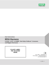
1. Jaw and locking button-2
2. D-ring-1
3. D-ring connector-1
4. Spacer-1
5. Cross bar-1
6. Glide pad-2
7. Barrel screw (-4) and bolt (-6)
8. Pin-2
9. Screw-2
10. Label-2
11. Load indictor
ESPAÑOL
1. Abrazadera y botón de segoro-2
2. Anillo en D-1
3. Conector del anillo en D-1
4. Espaciador-1
5. Travesaño-1
6. Placa de deslizamiento-2
7. Tornillo de barril (-4) y perno (-6)
8. Pasador-2
9. Tornillo-2
10. Etiqueta-2
11. Indicador de carga
FRANÇAIS
1. Mâchoire et bouton de verrouillage-2
2. Anneau en D-1
3. Connecteur à anneau en D-1
4. Entretoise-1
5. Traverse-1
6. Patin de glissement-2
7. Vis à corps cylindrique (-4) et boulon (-6)
8. Clavette d’arrêt-2
9. Vis-2
10. Étiquette-2
11. Indicateur de charge
8 7
1
2
11
3
4
6
10
9 5
PORTUGUÊS
1. Garra e botão de travamento-2
2. Argola-1
3. Conector-1 da argola
4. Espaçador-1
5. Travessa-1
6. Bloco de deslizamento-2
7. Cilindro (-4) e parafuso (-6)
8. Pino-2
9. Parafuso-2
10. Etiqueta-2
11. Indicador de queda

Page 5© 2013 MSA
P/N 10145808
ENGLISH
1.0 WORKMAN FP STRYDER SPECIFICATIONS
● TheWORKMANFPStrydermeetsANSIZ359.1-2007andOSHA29CFRPart1910.66AppendixC.
● Capacity:400lbs(182kg)includingweightoftheuserplustools,clothingandotheruser-borneobjects.
● Weight: ○ Model10144431:5lbs(2.3kg)
○ Model10144432:11.9lbs(5.4kg)
● Flangecapacity: ○ Model10144431:4.00inch(10.2cm)to13.5inch(34.3cm)
○ Model10144432:14.00inch(35.6cm)to23.5inch(59.7cm)
● Materialsofconstruction: ○ Housing,Button,Spring,pin,D-ringconnector:Stainlesssteel
○ Glidepads:Teonimpregnatedthermalplastic.
○ D-ring:Alloysteel.
○ Crossbar: ■ Model10144431:Aluminumalloy
■ Model10144432:Alloysteel
● Whenusedaspartofapersonalfallarrestsystem,fallarrestforcesmustnotexceed1800IBF(8kN).
● Freefalldistance(limit)mustnotexceed6.0ft(1.8m)inaccordanceOSHA,andANSIZ359.1-2007.Theusermustcomplywithapplicable
standards.
2.0 TRAINING
ItistheresponsibilityofthepurchaseroftheWORKMANFPSTRYDERtoassurethatproductusersaremadefamiliarwiththeseuserinstructionsand
trainedbyacompetentperson.Trainingmustbeconductedwithoutundueexposureofthetraineetohazards.MSAofferstrainingprograms,please
contactfortraininginformation.
3.0 DESCRIPTION
TheWORKMANFPSTRYDERisanI-beamanchorageconnector.TheintendedpurposeofeachelementoftheWORKMANFPSTRYDERisgiven
insections3.1through3.3below.Seeinspectiondiagramforlocationofelements.
3.1 ATTACHMENT ELEMENTS
3.1.1 D-RING
Usedforconnectiontoalanyardelementofapersonalfallarrestsystem.
3.1.2 JAW
UsedforconnectiontotheI-beamanchorage.
3.2 CROSSBAR
Thecrossbarconnectsandprovidesthemeansforadjustmentofthejaws,andanchorstheD-ringconnector.
3.3 D-RING CONNECTOR
TheD-ringconnectorconnectstheD-ringtothecrossbar,andprovidesanintegralloadindicator.
4.0 ANCHORAGE CONNECTOR SELECTION AND APPLICATIONS
4.1 PURPOSE OF ANCHORAGE CONNECTOR
TheWORKMANFPStryderisdesignedforusebyonepersonworkingatanelevatedworklevel.TheWORKMANFPStryderlinkstheusertoan
I-beamanchoragepoint.ItallowstheworkertoutilizeexistingI-beamastemporaryanchors,withouttheneedfordrillingorpermanentlyattaching
anchorages.Itmoveswiththeworkerallowingforcontinuoustieoff.
4.2 USAGE LIMITATIONS
ThefollowingapplicationlimitationsmustbeconsideredandplannedforbeforeusingtheWORKMANFPStryder.
4.2.1 PHYSICAL LIMITATIONS
Personswithmuscular,skeletal,orotherphysicaldisordersshouldconsultaphysicianbeforeusing.Pregnantwomenandminorsmustneveruse
theWORKMANFPStryder.Increasingageandloweredphysicaltnessmayreduceaperson’sabilitytowithstandshockloadsduringfallarrestor
prolongedsuspension.Consultaphysicianifthereisanyquestionaboutphysicalabilitytosafelyusethisproducttoarrestafallorsuspend.
4.2.2 ENVIRONMENT
Chemicalhazards,heatandcorrosionmaydamagetheWORKMANFPStryder.Morefrequentinspectionsarerequiredintheseenvironments.Do
notuseinenvironmentswithtemperaturesgreaterthan185ºF(85ºC).Usecautionwhenworkingaroundelectricalhazards,movingmachineryand
abrasivesurfaces.

Page 6 © 2013 MSA
P/N 10145808
5.0 SYSTEMS REQUIREMENTS
5.1 COMPATIBILITY OF SYSTEM PARTS
5.1.1 COMPATIBILITY OF COMPONENTS AND SUBSYSTEMS
WORKMANFPStryderaredesignedtobeusedwithotherMSAApprovedproducts.UseoftheWORKMANFPStryderwithproductsmadebyothers
thatarenotapprovedinwritingbyMSAmayadverselyaffectthefunctionalcompatibilitybetweensystempartsandthesafetyandreliabilityofthe
completesystem.
5.1.2 COMPATIBILITY OF CONNECTORS
Connectors,suchasD-rings,snaphooks,andcarabinersmustberatedat5000Ibf(22.2kN)minimumcapacity.MSAconnectorsmeetthisrequirement.
Connectinghardwaremustbecompatibleinsize,shapeandstrength.Non-compatibleconnectorsmayaccidentallydisengage(“rollout”).Always
verifythattheconnectingD-ringontheWORKMANFPStryderiscompatiblewiththesnaphook,orcarabinerofthelanyardsubsystem.
5.1.3 ANCHORAGES
TheacceptableanchoragefortheWORKMANFPStryderisahorizontalI-beam.TheI-beammustbeconguredsothattheWORKMANFPStryder
cannotcomeofftheendofthebeamandhaveastrengthcapableofsupportingastaticload,appliedinthedirectionspermittedbythesystem,of
atleast:(a)3600Ibf.(16kN)whencerticationexists,or(b)5000Ibf(22.2kN)intheabsenceofcertication.SeeANSIZ359.1-2007fordenitionof
certicate.Whenmorethanonepersonalfallarrestsystemisattachedtoananchorage,theanchoragestrengthssetforthin(a)and(b)mustbe
multipliedbythenumberofsystemsattachedtotheanchorage.SeeANSIZ359.1-2007,Section7.2.3.ThisrequirementisconsistentwithOSHA
requirementsunderCFR1910,subpartF,Section1910.66,AppendixC.Inaddition,itisrecommendedthattheuserofpersonalfallarrestsystems
refertoANSIZ359.1-2007,Section7,forimportantconsiderationsinequipmentselection,rigging,useandtraining.
6.0 PLANNING THE USE OF SYSTEMS
6.1 FREE FALL DISTANCE, TOTAL FALL DISTANCE AND SYSTEM ELONGATION
1.Freefalldistance.Limitedto6ft.(1.8m)byOSHAandANSIZ359.1-2007.ANSIA10.32limitedto5ft.(1.5m)byCanadianregulations.
2.Totalfalldistance.Thesumofthefreefalldistanceanddecelerationdistanceplusa3ftsafetymargin.
3.Decelerationdistance.Mustnotexceed3.5ft(1.1m).
6.2 PENDULUM (SWING) FALLS
Swingfallhazardsmustbeminimizedbyanchoringdirectlyabovetheuser’sworkspace.Theforceofstrikinganobjectinapendularmotioncancause
seriousinjury.Alwaysminimizeswingfallsbyworkingasdirectlybelowtheanchoragepointaspossible.
6.3 RESCUE AND EVACUATION
Theusermusthavearescueplanandthemeansathandtoimplementit.Theplanmusttakeintoaccounttheequipmentandspecialtraining
necessarytoeffectpromptrescueunderallforeseeableconditions.
7.0 CARE, MAINTENANCE AND STORAGE
7.1 CLEANING INSTRUCTIONS
Useacleandamp(notwet)clothtoremovedirtorcontaminationwhichmaycausecorrosionorhamperreadabilityoflabels.Wipeoffanymoisture
beforereturningthedevicetoservice.Thefrequencyofcleaningshouldbedeterminedbyinspectionandbyseverityoftheenvironment.Inhighly
corrosiveenvironmentscleaningshouldbedoneeverytwoorthreedays.Neverusesolventstocleanthedeviceastheymaydamagetheplastic
components.Don’tuseabrasivestoscourthedeviceastheymaydamagethesurfaceandthelabels.Toremoveoilorgrease,useamilddishwater
detergentonadampclothorspongeandfollowbyrepeatedswabbingwithacleanclothtoremoveallsoapresidue.Neverimmersetheproductin
waterorotherliquid.
7.2 STORAGE
Storethedeviceinaclean,dryplaceindoors.Storetheproductawayfromheatandsteamandneverallowittorestforlengthyperiodsoftimeon
concreteorashoorsasthelimesulfurandashcancausecorrosion.
7.3 MAINTENANCE
Usermaintenanceconsistsofcleaninganddryingthedeviceandreplacementoftheglidepad.Allothermaintenanceorrepair/workmustbedoneat
thefactoryorbyanauthorizedperson.(AuthorizationbyMSAmustbewritten).
8.0 MARKINGS AND LABELS
Thelabelsmustbepresent,legibleandsecurelyattachedtotheWORKMANFPSTRYDER.Thelabelsarelocatedonthesidesofthejaws.

Page 7© 2013 MSA
P/N 10145808
9.0 USAGE
9.1 WORKMAN FP STRYDER INSPECTION BEFORE EACH USE
InspecttheWORKMANFPSTRYDERtoverifyitisinserviceablecondition.Examineentiredeviceforsignsofcrackingordeformation.SeeSection
10forinspectiondetails.DonotuseaWORKMANFPSTRYDERifinspectionofitrevealsanunsafecondition.
9.2 MAKING PROPER CONNECTIONS
WhenconnectingtheD-ringoftheWORKMANFPSTRYDERtoalanyardsubsystem,becertainaccidentaldisengagement(“rollout”)cannotoccur.
Rolloutispossiblewheninterferencebetweenasnaphookandthematingconnectorcausesthesnaphook’sgateorkeepertoaccidentallyopen
andrelease.Rolloutoccurswhenasnaphookissnappedintoanundersizedringsuchasaneyeboltorothernon-compatiblyshapedconnector.
Onlyselfclosing,selflockingsnaphooksandcarabinersshouldbeusedtoreducethepossibilityofrolloutwhenmakingconnections.Donotuse
snaphooksorconnectorsthatwillnotcompletelycloseovertheattachmentobject.Donotmakeknotsinalanyard.Donothookalanyardbackonto
itself.Snaphooksandcarabinersmustnotbeconnectedtoeachother.DonotattachtwosnaphooksintooneD-ring.Alwaysfollowthemanufacturer’s
instructionssuppliedwitheachsystemcomponent.
9.3 CONNECTING THE WORKMAN FP STRYDER
TheWORKMANFPSTRYDERmaybeusedinaboveorbelowbeamapplications.TousetheWORKMANFPSTRYDER,depressthebuttonsto
unlockthejawsandslidethejawsfarenoughaparttotovertheangeoftheI-beamanchorage(SeeFIG1).Pushthejawstogethertocapturethe
angeoftheI-beam.Releasethebuttonstolockthejawtothecrossbar.Fineadjustthejawstot,byalternatinglockingthejawsinthedifferently
placedslotinthecrossbar(SeeFIG2).Themaximumtotalclearancebetweenthejawsandtheangeis0.5inch(12.7mm)(SeeFIG5).Verifythe
jawsarelockedintothecrossbar(SeeFIG3).TheusercanthenconnectthesnaphookorcarabineroftheirlanyardsubsystemtotheD-ringofthe
WORKMANFPSTRYDER(SeeFIG4).Becertainthesnaphookorcarabinergateiscompletelyclosedandlocked.
9.4 MOVING AROUND THE WORK AREA
TheWORKMANFPSTRYDERisdesignedtomovealongtheangeoftheI-beamanchorage,followingtheusermovements.Movearoundcarefully
topreventlossofbalanceintheeventtheWORKMANFPSTRYDERbindsorcontactsanobstacleinthepathofmovement.
!
WARNING
DO NOT exceed the allowable free fall distance as specied by governing standards subsystem components.
DO NOT exceed the maximum fall arrest forces as specied by governing standards subsystem components.
The capacity of the WORKMAN FP Stryder must be greater or equal the sub-system components.
9.5 GENERAL PRECAUTIONS
Donotaltertheequipment.Donotpasslanyardsubsystemcomponentsoversharpedgesorabrasivesurfaces.
!
WARNING
Use the WORKMAN FP STRYDER only on horizontal beams.
10.0 INSPECTION
10.1 INSPECTION FREQUENCY
TheWORKMANFPSTRYDERmustbeinspectedbytheuserbeforeeachuse.Additionally,theWORKMANFPSTRYDERmustbeinspectedbya
competentpersonotherthantheuseratintervalsofnomorethansixmonths.ThecompetentpersoninspectionisreferredtoasFormalInspection.
AninspectionlogmustbelledoutduringtheFormalInspection,seesection11.0.Inaddition,theinspectionlogontheWORKMANFPSTRYDER
labelmustbemarkedorpunchedtoindicatewhenthelastFormalInspectionoccurred.
!
WARNING
If the WORKMAN FP STRYDER has been subjected to fall arrest forces or impact it must be removed from
service and destroyed.
10.2 PROCEDURE FOR INSPECTION
Performthefollowingstepsinsequence.Ifindoubtaboutanyinspectionpoint,consultMSAoracompetentpersonwhoisqualiedtoperformFormal
InspectionassetforthinSection11.

Page 8 © 2013 MSA
P/N 10145808
Step1: InspecttheWORKMANFPSTRYDERlabelstoverifythattheyarepresentandlegible.SeeSection8forthespeciclabelsthatshouldbe
presentandtheinformationcontainedthereon.ChecktheFormalInspectionLogtobesureaFormalInspectionhasbeenperformedwithin
thelastsixmonths.IftheLogdoesnotindicatethataFormalInspectionhasbeenperformedwithinthelastsixmonths,orifanylabelsare
missingorillegible,removethedevicefromuseandmarkitas“UNUSABLE”untilaFormalInspectionisperformedbyacompetentperson.
Step2: Checktheautocloseactionofthebutton.Depressbuttonwiththumb,andensureautoclosing.Ifbuttonfailsthesefunctionaltests,returnto
maintainfromservice.
Step3: Checkforstructuraldefectsandcorrosion.Verifythatarenomissing,loosescreworalteredparts;thattherearenocracks,deformations,or
excessivecorrosion.
Step4: InspecttheD-ringfordeformation,fractures,cracks,corrosion,deeppitting,burrs,sharpedges,cuts,deepnicks,andevidenceofexcessive
heatorchemicalexposures.Checkthepinwithscrewfornodeformation,fractures,cracks,corrosion,pittingandnicks.Verifythescrewin
thepintightly.Ifthescrewswhichconnectedwithpinsareloose,removethedevicefromuseandmakeIt“UNUSABLE”.
Step5: InspecttheloadindicatingD-ringconnectorforactivation.Ifthedevicehasbeenexposedtoafallarrestforcethewindowwillbedeformed,
removethedevicefromuseandmakeit“UNUSABLE”.
Step6: Inspecteachcomponentandsubsystemofthecompletesysteminaccordancewiththeassociatedmanufacturer’sinstructions.Seesection
6foradescriptionofthemakeupofthedifferenttypesofsubsystemandsystems.
10.3 CORRECTIVE ACTION
Wheninspectionrevealssignofinadequatemaintenance,theWORKMANFPSTRYDERmustbeimmediatelyremovedfromserviceandmarked
as“UNUSABLE”untildestroyedorsubjectedtocorrectivemaintenance.Defects,damage,excessivewear,malfunctionandagingaregenerallynot
repairable.IfdetectedimmediatelyremovetheWORKMANFPSTRYDERfromuseandmarkitas“UNUSABLE”untildestroyed.Fornaldisposition,
submittheWORKMANFPSTRYDERtoacompetentpersonwhoisauthorizedtoperformFormalInspection.Ifthereisanyquestionastoreliability,
contactMSA,oraservicecenterauthorizedinwritingbyMSA,beforefurtheruseofthedevice.
!
CAUTION
Only MSA or parties with written authorization from MSA may make repairs to the MSA WORKMAN FP STRYDER.
11.0 INSPECTION LOG:
ModelNo.:_________________________________________________ Inspector:__________________________________________________
SerialNo.:_________________________________________________ InspectionDate:_____________________________________________
DateMade:________________________________________________ Disposition:_________________________________________________
Comments:____________________________________________________________________________________________________________
____________________________________________________________________________________________________________
____________________________________________________________________________________________________________

Page 9© 2013 MSA
P/N 10145808
WARRANTY
Express Warranty – MSA warrants that the product furnished is free from mechanical defects or faulty workmanship for
a period of one (1) year from rst use or eighteen (18) months from date of shipment, whichever occurs rst, provided it
is maintained and used in accordance with MSA’s instructions and/or recommendations. Replacement parts and repairs
are warranted for ninety (90) days from the date of repair of the product or sale of the replacement part, whichever
occurs rst. MSA shall be released from all obligations under this warranty in the event repairs or modications are made
by persons other than its own authorized service personnel or if the warranty claim results from misuse of the product.
No agent, employee or representative of MSA may bind MSA to any afrmation, representation or modication of the
warranty concerning the goods sold under this contract. MSA makes no warranty concerning components or accessories
not manufactured by MSA, but will pass on to the Purchaser all warranties of manufacturers of such components. THIS
WARRANTY IS IN LIEU OF ALL OTHER WARRANTIES, EXPRESS, IMPLIED OR STATUTORY, AND IS STRICTLY
LIMITED TO THE TERMS HEREOF. MSA SPECIFICALLY DISCLAIMS ANY WARRANTY OF MERCHANTABILITY OR
FITNESS FOR A PARTICULAR PURPOSE.
Exclusive Remedy - It is expressly agreed that the Purchaser’s sole and exclusive remedy for breach of the above
warranty, for any tortious conduct of MSA, or for any other cause of action, shall be the repair and/or replacement, at
MSA’s option, of any equipment or parts thereof, that after examination by MSA are proven to be defective. Replacement
equipment and/or parts will be provided at no cost to the Purchaser, F.O.B. Purchaser’s named place of destination.
Failure of MSA to successfully repair any nonconforming product shall not cause the remedy established hereby to fail of
its essential purpose.
Exclusion of Consequential Damages - Purchaser specically understands and agrees that under no circumstances will
MSA be liable to Purchaser for economic, special, incidental, or consequential damages or losses of any kind whatsoever,
including but not limited to, loss of anticipated prots and any other loss caused by reason of the non-operation of the
goods. This exclusion is applicable to claims for breach of warranty, tortious conduct or any other cause of action against
MSA.
For additional information please contact the Customer Service Department at 1-800-MSA-2222 (1-800-672-2222).
/