Page is loading ...

1 Rev. 1.3 03/12/10
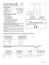
LG 2218 electronic control unit
An electronic control unit for the automation of 4 motors for roll-
ing window shutters and/or sun blinds, with optional connection
of Wind, Sun and Rain.
T
ECHNICAL
S
PECIFICATIONS
- Power supply: 230V~ 50/60Hz 1700W max.
- Motor output: 230V~ 400W Max.
- Working temperature: -10 to 55°C
- Packaging dimensions: 190x140x70 mm.
- Container: ABS UL94V-0 ( IP65 )
C
ONNECTION OF
CN1
T
ERMINAL
B
OARD
1: ~230V line input (Phase).
2: ~230V line input (Neutral).
3: Motor 1 Upward movement output.
4: Motor 1 Shared output.
5: Motor 1 Downward movement output.
6: Motor 2 Upward movement output.
7: Motor 2 Shared output.
8: Motor 2 Downward movement output
9: Motor 3 Upward movement output.
10: Motor 3 Shared output.
11: Motor 3 Downward movement output
12: Motor 4 Up output.
13: Motor 4 Shared output.
14: Motor 4 Downward movement output.
C
ONNECTION OF
CN2
T
ERMINAL
B
OARD
1: U1 Upward movement Local Input (NO).
2: GND shared Signal Input
3: D1 Downward movement Local Input (NO).
4: U2 Upward movement Local Input (NO).
5: GND shared Signal Input
6: D2 Downward movement Local Input (NO).
7: U3 Upward movement Local Input (NO).
8: GND shared Signal Input
9: D3 Downward movement Local Input (NO).
10: U4 Upward movement Local Input (NO).
11: GND shared Signal Input
12: D4 Downward movement Local Input (NO).
CN3
T
ERMINAL
B
LOCK
C
ONNECTIONS
1: 24 Vac Sun Sensor Power Output
2: “S” Sun Sensor Input (NO).
3: GND shared Input / 0 Vac Output
4: “R” Rain Sensor Input (NO).
5: GND shared Input
6: “W” Wind Sensor Input.
7: UZ Upward movement Zone Input (NO).
8: GND shared Input
9: DZ Downward movement Zone Input (NO).
10: UG Upward movement General Input (NO).
11: GND shared Input
12: DG Downward movement General Input (NO).
I
NITIAL
O
PERATING
C
ONDITION
The control unit allows you to control the 4 motors independ-
ently using the Local U1-2-3-4 (Up) or D1-2-3-4 (Down) con-
trols, and the UZ (Up zone), DZ (Down zone) and general UG
(Up) and DG (Down) simultaneous control keys. It is also pos-
sible to control the 4 motors together or independently.
FUNCTIONAL PROPERTIES:
Operation with Local Control or Zone Keys:
Connection to the U1-U2-U3-U4-UZ and D1-D2-D3-D4-DZ low
voltage inputs of the local control keys (normally open) for run-
running the shutter will ensure the following operation:
U1-U2-U3-U4-UZ control raising for the configured motor time,
D1-D2-D3-D4-DZ control lowering of the shutter; sending a
command for the same direction before the motor stops run-
ning, the control unit stops the shutter; sending a command for
the opposite direction before the motor stops running, the con-
trol unit reverses the movement.
Operation with General Keys:
The following type of operation is obtained by connecting the
general command buttons (normally open) for movement acti-
vation to the low voltage inputs UG – DG:
UG controls upward movement until the motor running time
has elapsed and DG controls downward movement. If a com-
mand is sent in the same direction before the motor running
time has elapsed, the control unit will ignore the command; if a
command is sent in the opposite direction before the motor
running time has elapsed, the control unit will invert the direc-
tion of the motor.
Z
ONE AND
G
ENERAL
C
ENTRALIZATION
Centralization with cable and keys
The centralization of two or more control units via wire enables
simultaneous raising or lowering of the connected shutters. To
do this you need to connect the control units with a bus of
three wires in parallel to the inputs of the General UG (Up) and
DG (Down) commands and the “GND Signal” common refer-
ence.
This allows you to control the 4 motors independently or simul-
taneously with the UZ (Up) and DZ (Down) zone commands
and centralize other control units with the UG (Up) and DG
(Down) general commands.
A
NEMOMETER OPERATION
The electronic control unit raises the sun shade whenever the
wind exceeds the selected threshold.
S
UN
S
ENSOR OPERATION
The electronic control unit lowers the sun shade after 10 min-
utes of brightness greater than the Sun Sensor’s selected
threshold; this is indicated by the SUN LED which lights up.
The control unit then raises the blind after 10 minutes during
which the brightness is below the selected threshold.
R
AIN
S
ENSOR OPERATION
The electronic control unit raises the blind as soon as the sen-
sitive part of the rain sensor is touched by water. The RAIN
LED lights up.
P
ROGRAMMING
K
EYS AND
I
NDICATOR
L
ED
SEL key: this selects the function to be stored. The LED
flashes to indicate your selection. Keep pressing the key to find
the required function. The selection remains active for 15 sec-
onds (during which time the LED keeps flashing) after which
the control unit then returns to its original state.
SET key: this key programs the function selected with the SEL
key.
Indicator LED
LED on: stored option.
LED off: option not stored.
LED flashing: option selected.
GB

2 Rev. 1.3 03/12/10
---------------------- MAIN MENU -----------------
LED reference LED off LED on
1) CODE M1 -
2) CODE M2 -
3) CODE M3 -
4) CODE M4 -
5) CODE SENS. -
6) T. MOT. Motor time 2 min. Motor time Pgm.
7) WIND SPEED Wind safety 25 Km/h Wind safety
Pgm.
8) SUN SENSOR Sun sensor = OFF Sun sensor
= ON
9) RAIN SENSOR Rain sensor = OFF Rain sensor
= ON
10) SUN Presence of Sun = No Presence of Sun = Yes
11) RAIN Presence of Rain = No Presence of Rain = Yes
1) CODE M1 Not used in this model
2) CODE M2 Not used in this model
3) CODE M3 Not used in this model
4) CODE M4 Not used in this model
5) CODE SENS. Not used in this model
6) LED T. MOT. (Programming Motor Time, max 4 minutes)
The control unit comes with a motor power time set at two min-
utes (LET T.MOT. OFF).
The motor time must be programmed as follows when the shut-
ter is down:
Press the SEL key until the LED T.MOT key flashes, then
press and hold the SET key to raise the shutter; release the
key when the blind is at the required point; the motor time is
stored at the same time and the LED T.MOT key stays ON.
If you are using an automation system with a stop limit, we
recommend that you store a time that exceeds the shutter’s
stop limit by a few seconds.
If you require unlimited motor time, follow the same program-
ming instructions holding down the SET key for less than two
seconds; the LED T.MOT stays ON and the unlimited time is
set. The operation may be repeated if a mistake is made dur-
ing programming.
7) WIND SPEED (Programming Wind Threshold)
Displaying the programmed Wind threshold
The wind safety threshold selection is displayed as follows: use
the SEL key to navigate to the WIND SPEED LED; the LED
then indicates the wind safety threshold, whereby every dou-
ble-flash of the WIND SPEED LED indicates an increment of 5
km/h (e.g. the WIND SPEED LED flashes 5 times = 25 km/h).
Setting the wind safety threshold between 5 and 40 Km/h
The control unit comes with a wind safety threshold already set
at 25 km/h (WIND SPEED LED OFF).
The wind safety threshold is programmed as follows: use the
SEL key to navigate to the WIND SPEED LED, then press the
SET key to start programming; the WIND SPEED LED will then
begin to double-flash (each double flash of the WIND SPEED
LED corresponds to an increment of 5 km/h). Press the SET
key once the required threshold has been reached. The se-
lected threshold is stored and the WIND SPEED LED stays ON
(e.g. the WIND SPEED LED flashes 5 times = 25 km/h).
The operation may be repeated if a mistake is made during
programming.
8) SUN SENSOR (Sun Sensor ON/OFF)
Enabling the sun sensor
The control unit comes with a Sun Sensor disabled (SUN
SENSOR LED OFF).
The Sun Sensor can be enabled as follows: use the SEL key to
navigate to the SUN SENSOR LED then press the SET key for
a second. The SUN SENSOR LED stays ON at the same time.
The Sun Sensor is now enabled. Simply repeat this procedure
to disable the Sun Sensor.
9) RAIN SENSOR (Rain sensor ON/OFF)
Disabling the rain sensor
The control unit comes with a Rain Sensor enabled (RAIN
SENSOR LED ON).
The Rain Sensor can be disabled as follows: use the SEL key
to navigate to the RAIN SENSOR LED, then press and hold
the SET key for a second. The RAIN SENSOR LED switches
off and the Rain Sensor is disabled. Simply repeat this proce-
dure to enable the Rain Sensor.
EXTENDED MENU
The manufacturer provides the control unit with only the option
of selecting the functions of the main menu.
If you wish to enable the functions of the extended menu, pro-
ceed as follows: press and hold the SET key for 5 seconds; the
SUN and RAIN LEDs will flash alternately; you then have 30
seconds within which to select the functions of the extended
menu using the SEL and SET keys; after another 30 seconds
the control unit returns to the main menu.
---------------------- EXTENDED MENU -----------------
LED reference LED off LED on
A) CODE M1 Step by step Manual/ P-P S. Aut.
B) CODE M2 Step by step Venetian blind / P-
P S. Aut.
C) CODE M3 Simultaneous start-up 5 sec sequential start-up
D) CODE M4 Start-up delay time = OFF Start-up delay time= Pgm
E) CODE SENS. Line Sensor test = OFF Line Sensor test
= ON
F) T. MOT. Aut shutdown = OFF Aut shutdown
= ON
G) WIND SPEED Safety up movmt = OFF Safety up movmt = ON
H) SUN SENSOR RAIN inversion = OFF RAIN inversion = ON
I) RAIN SENSOR SUN inversion = OFF SUN inversion
= ON
L) SUN ON/OFF intermittent
M) RAIN ON/OFF intermittent
A – B ) CODE M1 – M2
(4 different selectable operating logics):
Step by step:
Step by step operation is possible using the pushbutton con-
trol. The first impulsive control raises the blind for the motor
time. The second impulsive control lowers the blind. If an im-
pulsive command is sent before the motor stops running, the
control unit stops the blind; another impulsive command re-
activates the blind in the opposite direction.
Manual:
Manual operation is possible using the pushbutton control. The
control needs to be constantly enabled to move the blind. Re-
leasing the key will always stop operation.
Venetian blind operation:
The Venetian blind mode involves manual operation for the
first 2 seconds using pushbutton control; this allows you to turn
the slats of the Venetian blind ever so slightly to let more or
less light into the room as required. If the commands are more
than 2 seconds, the blind is raised or lowered depending on
the key pressed, until the motor stops running.
Step by step + Automatic sensors:
The control unit enables step by step operation as above, as
well as automatic management of the Wind and Rain sensors.
Ten minutes after the wind or rain that activated one of the two
sensors, the control unit lowers the blind.
Selection mode:
The control unit allows you to select 4 different operating lo-
gics: step by step, manual, Venetian blind and step by step +
automatic sensors.
The control unit is provided with step by step operation already
enabled (M1 CODE LED AND M2 CODE LED disabled). If you

3 Rev. 1.3 03/12/10
wish to enable the other operating mode, proceed as follows:
enable the extended menu (the SUN and RAIN LEDs will flash
to confirm this); use the SEL key to navigate to the M1 CODE
LED, then press the SET key to enable the Manual function;
use the SEL key to navigate to the M2 CODE LED, then press
the SET key to enable the Venetian blind function, or use the
SEL key to navigate to the M1 CODE LED and M2 CODE LED,
then press the SET key to enable the Step by step + Automatic
Sensors function.
C) CODE M3
(Simultaneous or sequential start-up):
The control unit is provided with simultaneous start-up of the 4
motors already enabled. If you wish to have a 5-second interval
in between the start-up of each motor, proceed as follows: en-
able the extended menu (the SUN and RAIN LEDs flash to
confirm this), use the SEL key to navigate to the CODE M3
LED and then press the SET key; at the same time the CODE
M3 LED switches on permanently and programming is ended.
Simply repeat this procedure to restore the previous configura-
tion.
D) CODE M4
(Programming the start-up delay time):
The control unit allows you to program a start-up delay time for
the 4 motors; this prevents other interconnected sets of 4 mo-
tors from starting up simultaneously. The control unit is pro-
vided without start-up delay time for the 4 motors; to program a
start-up delay time of between 1 and 120 seconds, proceed as
follows: enable the extended menu (the SUN and RAIN LEDs
will flash to confirm this), use the SEL key to navigate to the
CODE M4 LED, then press the SET key for the required delay
time; as soon as you release the key, the M4 CODE LED
switches on permanently and programming is complete. Sim-
ply repeat this procedure to make any changes to the configu-
ration.
E) SENS. CODE (Line Sensor Test):
The control unit allows you to check operation of the connected
sensors and correct movement. You are advised to install the
blind with it half open to check the confirmation movements
during the test. Make sure you disable the Line Sensor Test
after checking the sensors’ operation.
Anemometer test: turn the blades manually; the control unit
will raise the blind for 5 seconds.
Sun sensor test: expose the Sun Sensor to the sun or light
source; the control unit switches on the SUN LED and lowers
the blind for 5 seconds. Cover the Sun Sensor and the control
unit will switch off the SUN LED and raise the blind for 5 sec-
onds.
Rain sensor test: dampen the sensitive part of the Rain Sen-
sor; the control unit will switch on the RAIN LED and raise the
blind for 5 seconds. At the end of the test, make sure you dry
off the sensitive part of the rain sensor before using the control
unit in normal operating mode.
Programming: The control unit comes with a Line Sensor Test
disabled. If you wish to enable the Line Sensor Test, proceed
as follows: enable the extended menu (the SUN and RAIN
LEDs will flash to confirm this); use the SEL key to navigate to
the SENSOR CODE LED and then press the SET key; at the
same time, the SENSOR CODE LED switches on permanently
and programming is complete. Repeat this procedure to re-
store the initial configuration.
F) T. MOT. (Automatic Movement Lock):
The control unit allows you to lock automatic movement (Up-
ward or downward movement of the blind controlled by the Sun
Sensor command or function of the Automatic Sensors); in this
way, the control unit temporarily blocks automatic motion when
a stop command is given during movement until the next rais-
ing or lowering command. The control unit comes with the
Automatic Movement Lock disabled; to enable this function,
proceed as follows: enable the extended menu (the SUN and
RAIN LEDs flash to confirm this), press the SEL key until the
T.MOT LED flashes, then press the SET key; at the same time
the T.MOT LED switches on permanently and programming is
complete. Repeat this procedure to restore the previous con-
figuration.
G) WIND SPEED (Safety Upward Movement) :
The control unit comes with the Safety Upward Movement dis-
abled; to enable this function, so that after 12 hours of the
Wind Sensor being inactive the control unit automatically exe-
cutes the safety upward movement, proceed as follows: enable
the extended menu (the SUN and RAIN LED will flash to con-
firm this), press the SEL key until the WIND SPEED LED
flashes, then press the SET key; at the same time the WIND
SPEED LED switches on permanently and programming is
complete. Repeat this procedure to restore the previous con-
figuration.
H) SUN SENSOR (Sun sensor control inversion):
The control unit comes with the Sun control = Downward
movement control association, so the sensor controls the
downward movement of the blind when it detects the sun. If
you wish the sun sensor to control the upward movement of
the blind when it detects the sun, proceed as follows: enable
the extended menu (the SUN and RAIN LEDs flash to confirm
this), press the SEL key until the SUN SENSOR LED flashes,
then press the SET key; at the same time the SUN SENSOR
LED switches on permanently and programming is complete.
Repeat this procedure to restore the previous configuration.
I) RAIN SENSOR (Rain sensor control inversion):
The control unit comes with the Rain control = Upward move-
ment control association, so the sensor controls the upward
movement of the shutter when it detects the sun. If you wish
the rain sensor to control the downward movement of the shut-
ter when it detects the rain, proceed as follows: enable the ex-
tended menu (the SUN and RAIN LEDs flash to confirm this),
press the SEL key until the RAIN SENSOR LED flashes, then
press the SET key; at the same time the RAIN SENSOR LED
switches on permanently and programming is complete.
Repeat this procedure to restore the previous configuration.
R
ESET
If you need to restore the control unit’s default settings, press
the SEL and SET keys together to switch on all the indicator
LEDs at the same time and then switch them off again imme-
diately.

4 Rev. 1.3 03/12/10
I
MPORTANT NOTE FOR THE USER
- The device must not be used by children or people with any
psychological or physical disability, unless they are supervised
or taught how to use it with care.
- Do not let children play with the device.
- ATTENTION: keep this instruction manual and comply with
the important safety instructions inside. Failure to comply with
these instructions could cause damage and serious accidents.
- Inspect the system frequently to check for any signs of dam-
age. Do not use the device if it is in need of repair.
Attention
All operations that require opening the casing (cable connec-
tion, programming, etc.) must be executed during installation
by a qualified technician. Please contact the Technical Assis-
tance Service should any other work that requires opening the
casing arise (reprogramming, repair or installation changes).
SEAV s.r.l. declares that the products:
LG2218
Conform to the specifications of Directives EMC
2004/108/EC, LVD 2006/95/EC.
I
MPORTANT NOTES FOR THE INSTALLER
- The control unit was designed to allow the installer to auto-
mate the shutter in accordance with legislation in force. The
installer must comply with safety obligations and minimum re-
quirements.
Installation must be carried out according to EN 60335-2-97
“Specification for safety of household and similar electrical ap-
pliances” part 2 “Particular requirements for drives for rolling
shutters, awnings, blinds and similar equipment”
- The control unit must be connected permanently to the
power supply and it is not equipped with a 230 V a/c electric
line sectioning device. The installer is responsible for installing
a sectioning device in the system. He should install an omni-
polar switch with category III overvoltage. It must be posi-
tioned so that it is protected against accidental closure.
- For connections (power supply and motors output), use flexi-
ble cables under insulating sheath in harmonised polychloro-
prene H05RN-F with minimum section of the conductors equal
to 1.5 mm2
- Pay attention while making holes in the outside casing,
when passing cables for connection and power supply and as-
sembling the cable glands, that everything is installed in a way
that keeps IP protection characteristics of the panel un-
changed as much as possible.
Pay careful attention when fastening the cables so that they
are anchored in a manner that is stable.

5 Rev. 1.3 03/12/10
/