LG M4224C-BAP User manual

Type
User manual

This manual is also suitable for

Make sure to read the
Safety Precautions
before using the product.
Keep the User's Guide(CD) in an accessible place for future reference.
See the label attached on the product and give the information to your dealer when you ask
for service.
Users Guide
Sellers or users should understand that this device is for public use,
not home use.
M4224C
M4224F
1
First, check if the following parts are all present.
Stand (2)
Screws (4)
Parts
1. Take the parts for the stand out of the box and assemble them as
shown in the picture.
2. Place a soft cloth on the table and put the product with the screen
facing downward.
Connect the stand as shown in the following picture.
- Only on some models.
3. Use the screws to secure the stand on the rear side of the product as shown
in the diagram.
Connecting
the stand
2
Connecting the Speakers
Mount the product onto the speaker by using a screw as shown in the following
connect the speaker cable.
- Only on some models.
When the speaker is installed.
*Connect the input terminal with a proper color match.
Remove the paper.
Cable holder
After installing your speakers, use holders and cable ties to organize the speaker cables.
* This feature is not available in all model.
Cable tie
* This feature is not available in all model.
3
To install Portrait
- Only on some models.
"When installing Portrait, rotate it clockwise based on its front."
4
Using the Remote Control
Name of the Remote Control Buttons
1 2 3
4 5 6
7 8
0
9
*
AV Button
Sleep Button
When watching AV, RGB PC,HDMI/DVI,
Component
The product will be automatically turned
off after a certain period of time.
Press this button repetitively to
select an appropriate time duration
PSM Button
- Toggles through preset video
settings.
Menu Button
Check Button
Volume Button
Volume up and down
Mute button
There is not a function
which is supported
UP and Down buttons
Bring up and down direction
adjustment.
ARC button
Aspect Ratio Correction. Toggles
through aspect ratio options.
Auto Button
Automatic adjustment function
(Operational for the analog signal only)
Exit Button
There is not a function
which is supported
There is not a function
which is supported
There is not a function
which is supported
Power On/Off Button
Input Select Button
(See next page)
5
Using the Remote Control
AV Button
1 2 3
4 5 6
7 8
0
9
*
If you press the button once,
the following Input Signal
Window will appear. Select
the signal type you want
using the button.
Input Select Button
1. Slide off the battery cover.
2. Insert the batteries with correct polarity (+/-).
3. Close the battery cover.
• Dispose of used batteries in the recycle bin to prevent
environmental pollution.
Inserting batteries into remote control.
AAA Type
Input
AV
Component
RGB PC
HDMI/DVI
AV Component
RGB PC HDMI/DVI
Toggles through video
6
Name and Function of the Parts
Rear View
*LINE OUT
A terminal used to connect to the speaker including a built-in amplifier (Amp). Make sure that
the connecting terminal of the PC sound card is checked before connecting. If the Audio Out of
PC sound card has only Speaker Out, reduce the PC volume.
If the Audio Out of the PC sound card supports both Speaker Out and Line Out, convert to Line Out using
the card jumper of the program (Refer to the Sound Card Manual).
* The product image in the users guide could be different from the actual image.
Power Connector : Connect the power cord
RS-232C Serial Ports
RGB PC, HDMI/DVI Ports
-HDMI Supports High Definition input and HDCP (High-bandwidth Digital Content
Protection). Some devices require HDCP in order to display HD signals.
PC Sound Jack
: Connect the audio cable to the *LINE OUT jack of the PC sound card.
Wired Remote Control Port
AV Ports
LAN Port
Speaker Ports
AV IN/OUT
AV IN/OUT
AV IN/OUT
7
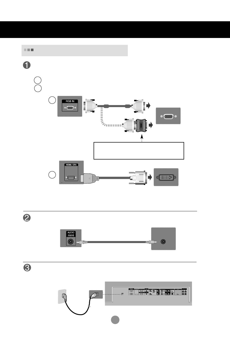
First of all, see if the computer, product and the peripherals are turned off.
Then, connect the signal input cable.
When connecting with the D-Sub signal input cable.
When connecting with the HDMI to DVI signal input cable (not included).
MAC
Macintosh Adapter (not included)
Use the standard Macintosh adapter since an incompatible
adapter is available in the market. (Different signaling system)
Rear side of the product.
Connecting to External Devices
Connect the power cord.
B
A
B
A
PC
When Connecting to your PC
PC/
MAC
PC
Rear side of the product.
PC
Rear side of the product.
Connect the Audio cable.
(not included)
* User must use shielded signal interface cables (D-sub 15 pin cable, DVI cable) with ferrite cores to maintain
standard compliance for the product.
8
Select an input signal.
Press the INPUT button on the remote control to select the input signal.
Or, press the SOURCE button on the back of the product.
INPUT SET
How to connect to two computers.
Connect the signal cables (
HDMI to DVI and D-Sub) to each computer.
Press the INPUT button on the remote control to select the computer to use.
Directly connect to a grounded power outlet on the wall or a power bar with a ground
wire.
Note
Turn on power by pressing the power button on the product.
Turn on the PC.
AUTO/SET
SOURCE
Power button
SOURCE
AUTO/SET
When connecting with a D-Sub signal input cable.
Select RGB PC : 15-pin
D-Sub
analog signal.
When connecting with a HDMI to DVI signal input cable.
Select HDMI/DVI :
HDMI to DVI
Digital signal.
B
A
Connecting to External Devices
2
1
Input
AV
Component
RGB PC
HDMI/DVI
Input
AV
Component
RGB PC
HDMI/DVI
9
Using LAN establishes communication between your PC and the monitor and enables to
use the OSD menus on the PC as well as on the monitor.
Note
Connecting to External Devices
Connect the Lan cable as shown in the below figure .
Connect the LAN cable and install the eZ-Net Manager program on the CD-ROM.
For more information about the program, please refer to eZ-Net Guide in the enclosed
CD-ROM.
When using the Lan
When connecting with a PC.
A
When connecting with a Network.
B
PC
Product
Network
Product
10
Use this function when displaying ANALOG RGB inputs of a PC to the other product.
RGB IN
RGB OUT
RGB IN
RGB OUT
RGB IN
RGB OUT
RGB IN
RGB OUT
Product 1
To use different products connected to each other
Connect one end of the signal input cable(15-pin D-Sub Signal Cable) to the RGB OUT
connector of product 1 and connect the other end to the RGB IN connector of other
products.
Daisy Chain Monitors
PC
Product 2
Product 3
Product 4
15-pin D-Sub Signal Cable
Connecting to External Devices
When multi-connecting in/out cascade format, no loss cables are recommended.
We recommend that you should use cable distributor.
Note
PC
11
The Set is equipped with a kensington Security
System connector on the back panel. The cable and
lock are available separate and are not sold by LG.
For more info, visit http://www.kensington.com, the
internet home page of the Kensington company.
VESA FDMI wall Mounting
This product supports a VESA FDMI compliant mounting interface. These mounts are purchased
separately and not available from LG. Refer to the instructions included with wall mount for more info.
Connecting to External Devices
12
Connecting to External Devices
When connecting with an BNC cable.
Select AV.
When connecting with an S-Video cable.
Select AV.
B
A
When connecting with a S-Video cable.
Connect to the S-Video input terminal to
watch high image quality movies.
Connect the video cable as shown in the below figure and then connect the power
cord (See page 7).
B
When connecting with a BNC cable.
Connect the input terminal with a
proper color match.
A
BNC Cable
(not included)
Product
VCR/DVD Receiver
Video Input
Select an input signal.
Press the INPUT button on the remote control to select the input signal.
Or, press the SOURCE button on the back of the product.
INPUT SET
SOURCE
AUTO/SET
When the BNC cable is connected simultaneously with S-Video cable, S-Video input has a priority.
Note
Audio Cable
(not included)
AUDIO
AV IN/OUT
S-Video Cable
(not included)
Audio Cable
(not included)
Product
VCR/DVD Receiver
Input
AV
Component
RGB PC
HDMI/DVI
13
Select Component
AUDIO
Connect the video/audio cable as shown in the below figure and then, connect the
power cord (See page 7).
Connect the input terminal with a proper color match.
BNC Cable
(not included)
Product
HDTV Receiver
Component Input (
480p/576p/720p/1080p/1080i/480i/576i)
Select an input signal.
Press the INPUT button on the remote control to select the input signal.
Or, press the SOURCE button on the back of the product.
INPUT SET
SOURCE
AUTO/SET
Audio Cable
(not included)
Connecting to External Devices
Input
AV
Component
RGB PC
HDMI/DVI
Note
- Some devices may require HDCP in order to display HD signals.
- Component doesn't support HDCP.
14
AUDIO
(RGB/DVI)
REMOTE
CONTROL IN
RGB IN
RGB OUT
HDMI/DVI IN
RGB IN
RGB OUT
HDMI/DVI IN
AUDIO
(RGB/DVI)
REMOTE
CONTROL IN
Connect the video/audio cable as shown in the below figure and then connect the
power cord (See page 7).
RCA-PC
Audio Cable
Product
VCR/DVD/Set-top Box
HDMI to DVI
Signal Cable
(not included)
HDMI Input (480p/576p/720p/1080i/1080p)
VCR/DVD/Set-top Box
Product
Select an input signal.
Press the INPUT button on the remote control to select the input signal.
Or, press the SOURCE button on the back of the product.
INPUT SET
SOURCE
AUTO/SET
HDMI Signal Cable
(not included)
Connecting to External Devices
When connecting with a HDMI to DVI signal input cable.
When connecting with a HDMI signal input cable.
Select HDMI/DVI
Input
AV
Component
RGB PC
HDMI/DVI
-HDMI Supports High Definition input and HDCP (High-bandwidth Digital Content
Protection). Some devices require HDCP in order to display HD signals.
Note : Dolby Digital is not supported.
15
- When using AV input, you can connect the AV Out to other monitors.
AUDIO
AV IN/OUT
Video/TV
Watching
AV Outputs
BNC Cable
(not included)
Audio Cable
(not included)
BNC Cable
(not included)
Audio Cable
(not included)
Video/TV
Product
Connecting to External Devices
When multi-connecting in/out cascade format, no loss cables are recommended.
We recommend that you should use cable distributor.
Note
16
User Menus
Screen Adjustment options
Press this button to turn on the power. Press this button again to
turn it off.
This Indicator lights up blue when the display operates normally(on
mode). If the display is in sleep (Energy Saving) mode, this indicator
color changes to amber.
Power Button
• Adjust the volume.
Adjust the up and down.
Use this button to show/hide the OSD (On Screen Display) menu
screen.
MENU Button
Use
this
button to select an icon or adjust the setting in the OSD screen.
OSD Select /
Adjust Button
Power Indicator
Volume
35
AUTO/SET
SOURCE
AUTO/SET
SOURCE
17
This is where the unit receives signals from the remote control.
Screen Adjustment options
[For PC Analog signal]
AUTO/SET Button
AV Composite Video, Separate Video
Component HDTV, DVD
RGB PC 15-pin D-Sub analog signal
HDMI/DVI Digital signal
- Toggles between inputs
SOURCE Button
SOURCE
AUTO/SET
Auto in progress
For opimal display change
resolution to 1920 X 1080
IR Receiver
User Menus
[When 1920 X1080 is selected]
Input
AV
Component
RGB PC
HDMI/DVI
18
User Menus
OSD Menu
Icon Function Description
Picture
Audio
Adjusts the audio options.
Adjusts screen brightness, contrast and color that you prefer.
Note
OSD(On Screen Display)
The OSD function enables you to adjust the screen status conveniently since it provides
graphical presentation.
Option
Adjusts the screen status according to the circumstances.
Time
Adjusts the timer options.
Information
Adjust Set ID and check Serial No. and SW version and IP
address
19
How to adjust the OSD (On Screen Display) screen
Use the remote control to adjust the OSD screen.
How to adjust the screen automatically
Press the AUTO/SET button (AUTO button on a remote Control) in the
PC analog signal. Then optimal screen settings will be selected that fit
into the current mode. If adjustment is not satisfactory, you can adjust
the screen manually.
Press the MENU Button, then the main menu of the OSD appears.
To access a control, use the Buttons.
When the icon you want becomes highlighted, press the SET Button.
Use the Buttons to adjust the item to the desired level.
Accept the changes by pressing the SET Button.
Exit the OSD by pressing the EXIT Button.
1
2
3
4
5
6
Pops up
the menu
screen
Move where
you want to
adjust
Move where
you want to
adjust
Select a
menu icon
Select a
menu icon
Adjust the status
Save
adjustment
Exit from the
menu screen.
User Menus
[When 1920 X1080 is selected]
  • Page 1 1
  • Page 2 2
  • Page 3 3
  • Page 4 4
  • Page 5 5
  • Page 6 6
  • Page 7 7
  • Page 8 8
  • Page 9 9
  • Page 10 10
  • Page 11 11
  • Page 12 12
  • Page 13 13
  • Page 14 14
  • Page 15 15
  • Page 16 16
  • Page 17 17
  • Page 18 18
  • Page 19 19
  • Page 20 20
  • Page 21 21
  • Page 22 22
  • Page 23 23
  • Page 24 24
  • Page 25 25
  • Page 26 26
  • Page 27 27
  • Page 28 28
  • Page 29 29
  • Page 30 30
  • Page 31 31
  • Page 32 32
  • Page 33 33
  • Page 34 34
  • Page 35 35
  • Page 36 36
  • Page 37 37
  • Page 38 38
  • Page 39 39
  • Page 40 40
  • Page 41 41
  • Page 42 42
  • Page 43 43
  • Page 44 44
  • Page 45 45
  • Page 46 46
  • Page 47 47
  • Page 48 48
  • Page 49 49
  • Page 50 50
  • Page 51 51
  • Page 52 52
  • Page 53 53
  • Page 54 54
  • Page 55 55
  • Page 56 56
  • Page 57 57
  • Page 58 58
  • Page 59 59
  • Page 60 60
  • Page 61 61
  • Page 62 62
  • Page 63 63
  • Page 64 64
  • Page 65 65
  • Page 66 66
  • Page 67 67
  • Page 68 68
  • Page 69 69
  • Page 70 70
  • Page 71 71
  • Page 72 72
  • Page 73 73
  • Page 74 74

LG M4224C-BAP User manual

Type
User manual
This manual is also suitable for

Ask a question and I''ll find the answer in the document

Finding information in a document is now easier with AI