Mettler Toledo Multi-parameter Transmitter M400 FF Operating instructions
- Category
- Measuring, testing & control
- Type
- Operating instructions

M400 FF
Multi-Parameter Transmitter
Instruction Manual

2 Transmitter M400 FF
Transmitter M400 FF © 02/2023 METTLER TOLEDO
30 078 302 H Printed in Switzerland
© It is forbidden to reprint this instruction manual in whole or part.
No part of this manual may be reproduced in any form, or modied, copied or distributed using electronic systems, in particular in the form
of photocopies, photographs, magnetic or other recordings, without written consent of Mettler-Toledo GmbH, Process Analytics, CH - 8902
Urdorf, Switzerland.
All rights reserved, in particular reproduction, translation and patenting/registration.
ISM is a trademark of the METTLER TOLEDO Group.

Transmitter M400 FF 3
© 02/2023 METTLER TOLEDO Transmitter M400 FF
Printed in Switzerland 30 078 302 H
Operation Manual
Multi-Parameter
Transmitter M400 FF

4 Transmitter M400 FF
Transmitter M400 FF © 02/2023 METTLER TOLEDO
30 078 302 H Printed in Switzerland
Content
1 Introduction ___________________________________________________________________________________________ 9
2 Safety Instructions _____________________________________________________________________________________ 10
2.1 DenitionofEquipmentandDocumentationSymbolsandDesignations ______________________________________ 10
2.2 Environmental protection __________________________________________________________________________ 11
2.3 Ex Instructions for M400 Series Multi-Parameter Transmitters – ATEX / IECEx / UKCA ______________________________ 12
2.4 Ex instructions for M400 Series Multi-Parameter Transmitters – FM Approval __________________________________ 14
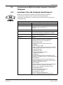
2.4.1 InstructionsofUsetoBeConsideredunderFMApproval ___________________________________________ 14
2.4.1.1 General Notes __________________________________________________________________ 16
2.4.1.2 CautionaryNotes,WarningsandMarkings ____________________________________________ 16
2.4.1.3 ControlDrawings _______________________________________________________________ 18
3 Unit Overview _________________________________________________________________________________________ 19
3.1 Overview½DIN _________________________________________________________________________________ 19
3.2 Control/NavigationKeys ___________________________________________________________________________ 20
3.2.1 Menu Structure ___________________________________________________________________________ 20
3.2.2 NavigationKeys __________________________________________________________________________ 20
3.2.2.1 NavigatingtheMenuTree _________________________________________________________ 20
3.2.2.2 Escape _______________________________________________________________________ 21
3.2.2.3 ENTER ________________________________________________________________________ 21
3.2.2.4 Menu _________________________________________________________________________ 21
3.2.2.5 CalibrationMode ________________________________________________________________ 21
3.2.2.6 Info Mode _____________________________________________________________________ 21
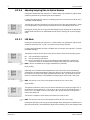
3.2.3 NavigationofDataEntryFields ______________________________________________________________ 21
3.2.4 EntryofDataValues,SelectionofDataEntryOptions _____________________________________________ 21
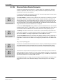
3.2.5 Navigationwith u inDisplay ________________________________________________________________ 22
3.2.6 ”SaveChanges”Dialog ____________________________________________________________________ 22
3.2.7 SecurityPasswords _______________________________________________________________________ 22
3.2.8 Display ________________________________________________________________________________ 22
4 Installation Instruction __________________________________________________________________________________ 23
4.1 UnpackingandInspectionofEquipment _______________________________________________________________ 23
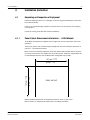
4.1.1 PanelCutoutDimensionalInformation–½DINModels ___________________________________________ 23
4.1.2 Installation Procedure _____________________________________________________________________ 24
4.1.3 Assembly–½DINVersion _________________________________________________________________ 24
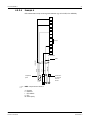
4.1.4 ½DINVersion–DimensionDrawings ________________________________________________________ 25
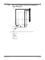
4.1.5 ½DINVersion–PipeMounting ______________________________________________________________ 25
4.2 ConnectionofPowerSupply ________________________________________________________________________ 26
4.2.1 Housing(WallMount) _____________________________________________________________________ 26
4.3 ConnectorPINDenition ___________________________________________________________________________ 27
4.3.1 TerminalBlock(TB)Denitions ______________________________________________________________ 27
4.3.2 TB2–Conductivity4-e/2-eAnalogSensors ____________________________________________________ 28
4.3.3 TB2–pH/ORPAnalogSensors ______________________________________________________________ 28
4.3.4 TB2–OxygenAnalogSensors ______________________________________________________________ 29
4.3.5 TB2–pH,Amp.Oxygen,Conductivity4-eandDissolvedCO2(Low)ISM(Digital)Sensors ________________ 29
4.3.6 TB2–OpticalOxygen,ISM(Digital)Sensors ____________________________________________________ 30
4.3.6.1 WithVP8Cable _________________________________________________________________ 30
4.3.6.2 WithotherCables _______________________________________________________________ 30
4.4 ConnectionofISM(Digital)Sensors __________________________________________________________________ 31
4.4.1 ConnectionofISMSensorsforpH/ORP,Cond4-e,Amp.OxygenMeasurementandDissolvedCO2(Low) _____ 31
4.4.2 TB2–AK9CableAssignment _______________________________________________________________ 31
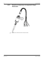
4.4.3 ConnectionofISMSensorsforOpticalOxygenMeasurement _______________________________________ 32
4.5 ConnectionofAnalogSensors ______________________________________________________________________ 33
4.5.1 ConnectionofAnalogSensorforpH/ORP ______________________________________________________ 33
4.5.2 TB2–TypicalWiringforAnalogpH/ORPSensor _________________________________________________ 34
4.5.2.1 Example 1 ____________________________________________________________________ 34
4.5.2.2 Example 2 ____________________________________________________________________ 35
4.5.2.3 Example 3 ____________________________________________________________________ 36
4.5.2.4 Example 4 ____________________________________________________________________ 37
4.5.3 ConnectionofAnalogSensorforAmperometricOxygenMeasurement ________________________________ 38
4.5.4 TB2–TypicalWiringforAnalogSensorforAmperometricOxygenMeasurement ________________________ 39
5 Placing Transmitter In, or Out, of Service ___________________________________________________________________ 40
5.1 PlacingTransmitterinService _______________________________________________________________________ 40
5.2 PlacingTransmitteroutofService ___________________________________________________________________ 40

Transmitter M400 FF 5
© 02/2023 METTLER TOLEDO Transmitter M400 FF
Printed in Switzerland 30 078 302 H
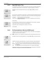
6 Quick Setup __________________________________________________________________________________________ 41
7 Sensor Calibration _____________________________________________________________________________________ 42
7.1 EnterCalibrationMode ____________________________________________________________________________ 42
7.2 ConductivityCalibrationforTwo-orFour-ElectrodeSensors ________________________________________________ 43
7.2.1 One-PointSensorCalibration ________________________________________________________________ 44
7.2.2 Two-PointSensorCalibration(OnlyforFour-ElectrodeSensors) _____________________________________ 45
7.2.3 ProcessCalibration _______________________________________________________________________ 45
7.3 CalibrationofAmperometricOxygenSensors ___________________________________________________________ 46
7.3.1 One-PointCalibrationforAmperometricOxygenSensors __________________________________________ 46
7.3.1.1 Auto Mode _____________________________________________________________________ 47
7.3.1.2 Manual Mode __________________________________________________________________ 47
7.3.2 ProcessCalibrationforAmperometricOxygenSensors ____________________________________________ 48
7.4 CalibrationofOpticalOxygenSensors(OnlyforISMSensors) ______________________________________________ 49
7.4.1 One-PointCalibrationforOpticalOxygenSensors ________________________________________________ 49
7.4.1.1 Auto mode ____________________________________________________________________ 49
7.4.1.2 Manual Mode __________________________________________________________________ 50
7.4.2 Two-PointSensorCalibration _______________________________________________________________ 50
7.4.2.1 Auto Mode _____________________________________________________________________ 51
7.4.2.2 Manual Mode __________________________________________________________________ 51
7.4.3 ProcessCalibration _______________________________________________________________________ 52
7.5 pHCalibration ___________________________________________________________________________________ 53
7.5.1 One-PointCalibration ______________________________________________________________________ 53
7.5.1.1 Auto Mode _____________________________________________________________________ 53
7.5.1.2 Manual Mode __________________________________________________________________ 54
7.5.2 Two-PointCalibration _____________________________________________________________________ 54
7.5.2.1 Auto Mode _____________________________________________________________________ 54
7.5.2.2 Manual Mode __________________________________________________________________ 55
7.5.3 ProcessCalibration _______________________________________________________________________ 55
7.5.4 mVCalibration(OnlyforAnalogSensors) ______________________________________________________ 56
7.5.5 ORPCalibration(OnlyforISMSensors) _______________________________________________________ 57
7.6 DissolvedCarbonDioxideCalibration _________________________________________________________________ 57
7.6.1 One-PointCalibration _____________________________________________________________________ 57
7.6.1.1 Auto Mode _____________________________________________________________________ 58
7.6.1.2 Manual Mode __________________________________________________________________ 58
7.6.2 Two-PointCalibration _____________________________________________________________________ 58
7.6.2.1 Auto Mode _____________________________________________________________________ 59
7.6.2.2 Manual Mode __________________________________________________________________ 59
7.6.3 ProcessCalibration _______________________________________________________________________ 60
7.7 SensorTemperatureCalibration(OnlyforAnalogSensors) ________________________________________________ 61
7.7.1 One-PointSensorTemperatureCalibration ______________________________________________________ 61
7.7.2 Two-PointSensorTemperatureCalibration ______________________________________________________ 61
7.8 EditSensorCalibrationConstants(OnlyforAnalogSensors) _______________________________________________ 62
7.9 SensorVerication ________________________________________________________________________________ 62
8 Conguration _________________________________________________________________________________________ 63
8.1 EnterCongurationMode __________________________________________________________________________ 63
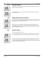
8.2 Measurement ___________________________________________________________________________________ 63
8.2.1 Channel Setup ___________________________________________________________________________ 63
8.2.1.1 AnalogSensor __________________________________________________________________ 64
8.2.1.2 ISM Sensor ____________________________________________________________________ 64
8.2.1.3 SaveChangesoftheChannelSetup _________________________________________________ 64
8.2.2 TemperatureSource(OnlyforAnalogSensors) __________________________________________________ 65
8.2.3 ParameterRelatedSettings _________________________________________________________________ 65
8.2.3.1 ConductivityTemperatureCompensation _____________________________________________ 66
8.2.3.2 ConcentrationTable _____________________________________________________________ 67
8.2.3.3 pH / ORP Parameters _____________________________________________________________ 68
8.2.3.4 ParametersforOxygenMeasurementBasedonAmperometricSensors ______________________ 69
8.2.3.5 ParametersforOxygenMeasurementBasedonOpticalSensors ___________________________ 71
8.2.3.6 AdjustingSamplingRateforOpticalSensors __________________________________________ 72
8.2.3.7 LED Mode _____________________________________________________________________ 72
8.2.3.8 DissolvedCarbonDioxideParameters _______________________________________________ 73
8.2.4 SetAveraging ____________________________________________________________________________ 74
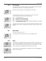
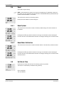
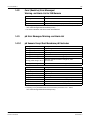
8.3 Alarm / Clean ___________________________________________________________________________________ 74
8.3.1 Alarm __________________________________________________________________________________ 74
8.3.2 Clean __________________________________________________________________________________ 76

6 Transmitter M400 FF
Transmitter M400 FF © 02/2023 METTLER TOLEDO
30 078 302 H Printed in Switzerland
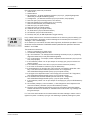
8.4 ISMSetUp(AvailableforpH,OxygenandDissolvedCarbonDioxidISMSensors) ______________________________ 77
8.4.1 SensorMonitoring ________________________________________________________________________ 77
8.4.2 CIPCycleLimit ___________________________________________________________________________ 79
8.4.3 SIPCycleLimit ___________________________________________________________________________ 79
8.4.4 AutoclavingCycleLimit ____________________________________________________________________ 80
8.4.5 Reset ISM Counter / Timer ___________________________________________________________________ 81
8.4.6 DLIStressAdjustment(OnlyforpHISMSensors) ________________________________________________ 81
8.5 Display ________________________________________________________________________________________ 82
8.5.1 Measurement ____________________________________________________________________________ 82
8.5.2 Resolution ______________________________________________________________________________ 82
8.5.3 Backlight _______________________________________________________________________________ 83
8.5.4 Name __________________________________________________________________________________ 83
8.5.5 ISMSensorMonitoring(AvailablewhenISMSensorConnected) _____________________________________ 83
8.6 Hold Outputs ____________________________________________________________________________________ 84
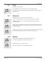
9 System ______________________________________________________________________________________________ 85
9.1 SetLanguage ___________________________________________________________________________________ 85
9.2 Passwords _____________________________________________________________________________________ 85
9.2.1 ChangingPasswords ______________________________________________________________________ 86
9.2.2 ConguringMenuAccessforOperator _________________________________________________________ 86
9.3 Set / Clear Lockout ________________________________________________________________________________ 86
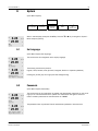
9.4 Reset __________________________________________________________________________________________ 87
9.4.1 ResetSystem ____________________________________________________________________________ 87
9.4.2 ResetMeterCalibration ____________________________________________________________________ 87
9.5 Set Date & Time _________________________________________________________________________________ 87
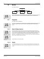
10 Service ______________________________________________________________________________________________ 88
10.1 Diagnostics _____________________________________________________________________________________ 88
10.1.1 Model / Software Revision ___________________________________________________________________ 88
10.1.2 Display ________________________________________________________________________________ 88
10.1.3 Keypad ________________________________________________________________________________ 89
10.1.4 Memory ________________________________________________________________________________ 89
10.1.5 ReadAnalogInputs _______________________________________________________________________ 89
10.1.6 02 Optical _______________________________________________________________________________ 89
10.2 Calibrate _______________________________________________________________________________________ 90
10.2.1 CalibrateMeter(OnlyforChannelA) __________________________________________________________ 90
10.2.1.1 Resistance ____________________________________________________________________ 90
10.2.1.2 Temperature ___________________________________________________________________ 91
10.2.1.3 Current _______________________________________________________________________ 92
10.2.1.4 Voltage _______________________________________________________________________ 93
10.2.1.5 RgDiagnostic __________________________________________________________________ 93
10.2.1.6 RrDiagnostic __________________________________________________________________ 94
10.2.1.7 CalibrateAnalogInputSignal ______________________________________________________ 94
10.2.2 CalibrateUnlock __________________________________________________________________________ 95
10.3 Tech Service ____________________________________________________________________________________ 95
11 Info _________________________________________________________________________________________________ 96
11.1 Messages ______________________________________________________________________________________ 96
11.2 CalibrationData _________________________________________________________________________________ 96
11.3 Model / Software Revision __________________________________________________________________________ 97
11.4 ISMSensorInfo(AvailablewhenISMSensorConnected) __________________________________________________ 97
11.5 ISMSensorDiagnostics(AvailablewhenISMSensorConnected) ___________________________________________ 97
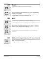
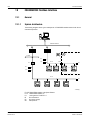
12 FOUNDATION Fieldbus Interface _________________________________________________________________________ 100
12.1 General _______________________________________________________________________________________ 100
12.1.1 SystemArchitecture ______________________________________________________________________ 100
12.2 M400 FF Block Model ____________________________________________________________________________ 101
12.2.1 BlockConguration ______________________________________________________________________ 102
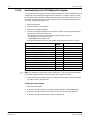
12.3 Commissioning _________________________________________________________________________________ 103
12.3.1 NetworkConguration ____________________________________________________________________ 103
12.3.2 IdenticationandAddressing _______________________________________________________________ 103
12.3.3 CommissioningviaanFFCongurationProgram _______________________________________________ 104
12.3.4 ScalingtheOUTParameter ________________________________________________________________ 106
13 Maintenance _________________________________________________________________________________________ 107
13.1 FrontPanelCleaning _____________________________________________________________________________ 107

Transmitter M400 FF 7
© 02/2023 METTLER TOLEDO Transmitter M400 FF
Printed in Switzerland 30 078 302 H
14 Troubleshooting ______________________________________________________________________________________ 108
14.1 Cond(Resistive)ErrorMessages /Warning-andAlarmListforAnalogSensors ________________________________108
14.2 Cond(Resistive)ErrorMessages /Warning-andAlarmListforISMSensors __________________________________109
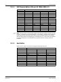
14.3 pHErrorMessages / Warning-andAlarmList _________________________________________________________109
14.3.1 pHSensorsExceptDualMembranepHElectrodes ______________________________________________ 109
14.3.2 DualMembranepHElectrodes(pH/pNa) ____________________________________________________ 110
14.3.3 ORPMessages _________________________________________________________________________ 110
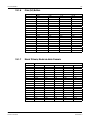
14.4 Amperometric O2ErrorMessages /Warning-andAlarmList_______________________________________________ 111
14.4.1 HighLevelOxygenSensors ________________________________________________________________ 111
14.4.2 LowLevelOxygenSensors ________________________________________________________________ 111
14.4.3 TraceOxygenSensors ____________________________________________________________________ 112
14.5 Optical O2ErrorMessages / Warning-andAlarmList ____________________________________________________112
14.6 DissolvedCarbonDioxideErrorMessages /Warning-andAlarmList _______________________________________113
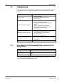
14.7 Warning-andAlarmIndicationontheDisplay ________________________________________________________114
14.7.1 WarningIndication_______________________________________________________________________ 114
14.7.2 Alarm Indication _________________________________________________________________________ 114
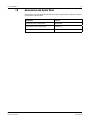
15 Accessories and Spare Parts ____________________________________________________________________________ 115
16 Specications ________________________________________________________________________________________ 116
16.1 GeneralSpecications ____________________________________________________________________________ 116
16.2 ElectricalSpecications ___________________________________________________________________________ 120
16.3 FOUNDATIONFieldbusSpecications ________________________________________________________________ 120
16.4 MechanicalSpecication _________________________________________________________________________ 121
16.5 EnvironmentalSpecications ______________________________________________________________________ 121
16.6 ControlDrawings _______________________________________________________________________________ 122
16.6.1 Installation,MaintenanceandInspection ______________________________________________________ 122
16.6.2 ControlInstallationDrawingGeneralInstallation ________________________________________________ 123
16.6.3 Notes _________________________________________________________________________________ 126
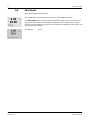
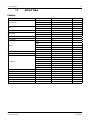
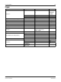
17 Default Table ________________________________________________________________________________________ 127
18 Warranty ____________________________________________________________________________________________131
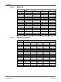
19 Buffer Tables _________________________________________________________________________________________ 132
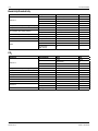
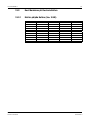
19.1 Standard pH Buffers _____________________________________________________________________________ 132
19.1.1 Mettler-9 _______________________________________________________________________________ 132
19.1.2 Mettler-10 _____________________________________________________________________________ 133
19.1.3 NIST Technical Buffers ____________________________________________________________________ 133
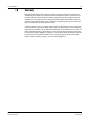
19.1.4 NISTStandardBuffers(DINandJIS19266:2000–01) __________________________________________ 134
19.1.5 Hach Buffers ___________________________________________________________________________ 134
19.1.6 Ciba(94)Buffers ________________________________________________________________________ 135
19.1.7 MerckTitrisole,Riedel-de-HaënFixanale ______________________________________________________ 135
19.1.8 WTWBuffers ___________________________________________________________________________ 136
19.1.9 JISZ8802Buffers _______________________________________________________________________ 136
19.2 DualMembranepHElectrodeBuffers ________________________________________________________________ 137
19.2.1 Mettler-pH/pNaBuffers(Na+3.9M) _________________________________________________________ 137

8 Transmitter M400 FF
Transmitter M400 FF © 02/2023 METTLER TOLEDO
30 078 302 H Printed in Switzerland

Transmitter M400 FF 9
© 02/2023 METTLER TOLEDO Transmitter M400 FF
Printed in Switzerland 30 078 302 H
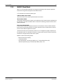
1 Introduction
StatementofIntendedUse–The2-wireM400multi-parametertransmitterisasingle-channel
onlineprocessinstrumentwithFOUNDATIONfieldbus™communicationcapabilitiesformeasur-
ingvariouspropertiesoffluidsandgases.TheseincludeConductivity,Oxygen.Theparameters
areindicatedonthelabelonthebackofthesystem.
TheM400isauniquemixedmodetransmitterwhocanhandleconventionalsensors(analog)
or ISM™sensors(digital).
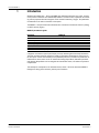
M400 FF parameter fit guide
Parameter M400 FF
Analog ISM
pH / ORP • •
Conductivity2-e • –
Conductivity4-e • •
Amp.DOppm/ppb/trace •/•/• •/•/•
Amp. O2 • •
OpticalOxygenppm/ppb – •/•
DissolvedCarbonDioxide(low) – •
AlargefourlinebacklitLiquidCrystalDisplayconveysmeasuringdataandsetupinformation.
Themenustructureallowstheoperatortomodifyalloperationalparametersbyusingkeyson
thefrontpanel.Amenu-lockoutfeature,withpasswordprotection,isavailabletopreventtheun-
authorizeduseofthemeter.ViatheFFinterfacetheAnalogOutputBlock,DescreteInputBlock
andDescreteOutputBlockcanbeconfiguredforAlarm/Cleanstatus,Holdstatusandpressure
compensation.
Thisdescriptioncorrespondstothefirmwarerelease,version1.0.02fortransmitterM400FF.
Changesaretakingplaceconstantly,withoutpriornotification.

10 Transmitter M400 FF
Transmitter M400 FF © 02/2023 METTLER TOLEDO
30 078 302 H Printed in Switzerland
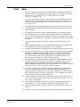
2 Safety Instructions
Thismanualincludessafetyinformationwiththefollowingdesignationsandformats.
2.1 DenitionofEquipmentandDocumentationSymbolsand
Designations
a WARNING:POTENTIALFORPERSONALINJURY.
a CAUTION:possibleinstrumentdamageormalfunction.
h NOTE:Importantoperatinginformation.
a Onthetransmitterorinthismanualtextindicates:Cautionand/orotherpossiblehazardinclud-
ingriskofelectricshock(refertoaccompanyingdocuments)
Thefollowingisalistofgeneralsafetyinstructionsandwarnings.Failuretoadheretothese
instructionscanresultindamagetotheequipmentand/orpersonalinjurytotheoperator.
– TheM400Transmittershouldbeinstalledandoperatedonlybypersonnelfamiliarwiththe
transmitterandwhoarequalifiedforsuchwork.
– TheM400Transmittermustonlybeoperatedunderthespecifiedoperatingconditions(see
section16“Specifications”).
– RepairoftheM400Transmittermustbeperformedbyauthorized,trainedpersonnelonly.
– Withtheexceptionofroutinemaintenance,cleaningproceduresorfusereplacement,asde-
scribedinthismanual,theM400Transmittermustnotbetamperedwithoralteredinany
manner.
– METTLERTOLEDOacceptsnoresponsibilityfordamagecausedbyunauthorizedmodifica-
tions to the transmitter.
– Followallwarnings,cautions,andinstructionsindicatedonandsuppliedwiththisproduct.
– Installequipmentasspecifiedinthisinstructionmanual.Followappropriatelocalandnation-
al codes.
– Protectivecoversmustbeinplaceatalltimesduringnormaloperation.
– Ifthisequipmentisusedinamannernotspecifiedbythemanufacturer,theprotectionpro-
videdbyitagainsthazardsmaybeimpaired.
a WARNINGS:
Installationofcableconnectionsandservicingofthisproductrequireaccesstoshockhazard
voltagelevels.
Mainpowerwiredtoseparatepowersourcemustbedisconnectedbeforeservicing.
Switchorcircuitbreakershallbeincloseproximitytotheequipmentandwithineasyreachof
theOPERATOR;itshallbemarkedasthedisconnectingdevicefortheequipment.Mainpower
mustemployaswitchorcircuitbreakerasthedisconnectingdevicefortheequipment.
ElectricalinstallationmustbeinaccordancewiththeNationalElectricalCodeand/oranyother
applicablenationalorlocalcodes.

Transmitter M400 FF 11
© 02/2023 METTLER TOLEDO Transmitter M400 FF
Printed in Switzerland 30 078 302 H
h NOTE:PROCESSUPSETSBecauseprocessandsafetyconditionsmaydependonconsistentop-
erationofthistransmitter,provideappropriatemeanstomaintainoperationduringsensor
cleaning,replacementorsensororinstrumentcalibration.
2.2 Environmentalprotection
Wasteelectricalproductsshouldnotbedisposedofwithhouseholdwaste.Pleasere-
cyclewherefacilitiesexist.CheckwithyourLocalAuthorityorretailerforrecycling
advice.

12 Transmitter M400 FF
Transmitter M400 FF © 02/2023 METTLER TOLEDO
30 078 302 H Printed in Switzerland
2.3 ExInstructionsforM400SeriesMulti-ParameterTransmitters –
ATEX/IECEx/UKCA
M400seriesmulti-parametertransmittersareproducedbyMettler-ToledoGmbH.
IthaspassedtheinspectionofIECExandconformstofollowingstandards:
– IEC60079-0:2017
Edition:7.0Explosiveatmospheres–
Part0:Generalrequirements
– IEC60079-11:2011
Edition:6.0Explosiveatmospheres–
Part11:Equipmentprotectionbyintrinsicsafety“i”
ExMarking:
– Exib[iaGa]IICT4Gb
– Exib[iaDa]IIICT80°CDbIP66
Certificate No.:
– IECExNEP18.0007X
– SEV12ATEX0132X
– CML22UKEX2209X
1.SpecialConditionsofuse(X-markingintheCertificateNumber):
1. Avoidignitionhazardduetoimpactorfriction,preventmechanicalsparks.
2. Avoidelectrostaticdischargeonenclosuresurface,usewetclothonlyforcleaning.
3. Inhazardousarea,IP66cableglands(assupplied)mustbemounted.
2. Pay particular attention to the following when using the transmitter:
1. Ratedambienttemperaturerange:
–forgasatmosphere: –20~+60°C
–fordustatmosphere: –20~+57°C
2. Nooperationontheupgradeinterfaceinhazardousarea.
3. Usersshallnotarbitrarilyreplacetheinternalelectricalcomponents.
4. Wheninstallation,useandmaintenance,IEC60079-14shouldbeobserved.
5. Wheninstallationinexplosivedustatmosphere
5.1CableglandorblankingplugtoIEC60079-0:2017andIEC60079-11:
2011withmarkingExiaIIICIP66shouldbeadopted.
5.2Theoverlayswitchofmulti-parametertransmittershallbeprotectedfromlight.
5.3Avoidhighriskofmechanicaldangerontheoverlayswitch.
6. Observethewarning:potentialelectrostaticcharginghazard-seeinstructions,avoidignition
hazard due to impact or friction for Ga application.
7. Forconnectiontointrinsicallysafecircuits,usethemaximumvaluesinthefollowingtable.

Transmitter M400 FF 13
© 02/2023 METTLER TOLEDO Transmitter M400 FF
Printed in Switzerland 30 078 302 H
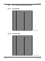
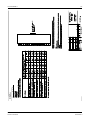
Terminal Function Safety Parameters
10,11 Power(FF)
FISCO field device Ui=17.5V Ii = 380 mA Pi=5.32W Li = 0 Ci = 3 nF
Linear power Ui=24V Ii = 200 mA Pi=1.2W Li = 0 Ci = 3 nF
P, Q Analoginput Ui=24V Ii = 100 mA Pi=0.8W Li = 0 Ci = 15 nF
N,O RS485 sensor Uo=5.88V
Ui=24V
Io = 54 mA
Ii = 100 mA
Po = 79
mW
Pi=0.8W
Lo = 1 mH
Li = 0
Co=1.9μF
Ci=0.7μF
L,M One-wire sensor Uo=5.88V Io = 22 mA Po = 32
mW Lo = 1 mH Co=2.8μF
I,J,K Temperature sensor Uo=5.88V Io = 5.4 mA Po=8mW Lo = 5 mH Co=2μF
B,C,D,H Dissolvedoxygen
sensor Uo=5.88V Io = 29 mA Po = 43
mW Lo = 1 mH Co=2.5μF
A,B,E,G Conductivitysensor Uo=5.88V Io = 29 mA Po = 43
mW Lo = 1 mH Co=2.5μF
A,E,G pH sensor Uo=5.88V Io = 1.3 mA Po = 1.9
mW Lo = 5 mH Co=2.1μF
LabelM400FF.

14 Transmitter M400 FF
Transmitter M400 FF © 02/2023 METTLER TOLEDO
30 078 302 H Printed in Switzerland
2.4 ExinstructionsforM400SeriesMulti-ParameterTransmitters–
FM Approval
2.4.1 InstructionsofUsetoBeConsideredunderFMApproval
M400seriesmulti-parametertransmittersareproducedbyMettler-ToledoGmbH.
IthaspassedtheinspectionofNRTLcFMusandtofollowingrequirements.
Theequipmentisprovidedwithaninternalbondwiringandaninternalflyingleadwirefor
groundingpurposes.
US marking
Operatingtemperaturerange –20°Cto+60°C(–4°Fto+140°F)
Environmentaldesignation Enclosuretype4X,IP66
Intrinsicallysafe –ClassI,Division1,GroupsA,B,C,DT4A
–ClassII,Division1,GroupsE,F,G
–Class III
Intrinsicallysafe ClassI,Zone0,AExiaIICT4Ga
Parameters –Entity:Controldrawing12112601and12112602
–FISCO:Controldrawing12112603and12112602
Nonincendive –ClassI,Division2,GroupsA,B,C,DT4A
–ClassI,Zone2,GroupsIICT4
Certicateno. 3046275
Standards –FM3810:2005
ApprovalStandardforElectricalEquipmentfor
Measurement,ControlandLaboratoryUse
–ANSI/IEC-60529:2004
DegreesofProtectionProvidedbyEnclosures
(IPCodes)
–ANSI/ISA-61010-1:2004
Edition:3.0SafetyRequirementsforElectricalEquipment
forMeasurement,Control,andLaboratoryUse–Part1:
GeneralRequirements
–ANSI/NEMA250:1991
EnclosuresforElectricalEquipment
(1,000VoltsMaximum)
–FM3600:2011
ApprovalStandardforElectricalEquipmentforUsein
Hazardous(Classied)Locations–GeneralRequirements
–FM3610:2010
ApprovalStandardforIntrinsicallySafeApparatusand
AssociatedApparatusforUseinClassI,II&III,Division1,
Hazardous(Classied)Locations
–FM3611:2004
ApprovalStandardforNonincendiveElectricalEquipment
forUseinClassI&II,Division2,andClassIII,
Division1&2,Hazardous(Classied)Locations
–ANSI/ISA-60079-0:2013
Edition:6.0ExplosiveAtmospheres–
Part0:GeneralRequirements
–ANSI/ISA-60079-11:2012
Edition:6.0ExplosiveAtmospheres–
Part11:EquipmentProtectionbyIntrinsicSafety“i”

Transmitter M400 FF 15
© 02/2023 METTLER TOLEDO Transmitter M400 FF
Printed in Switzerland 30 078 302 H
Canadian marking
Operatingtemperaturerange –20°Cto+60°C(–4°Fto+140°F)
Environmentaldesignation Enclosuretype4X,IP66
Intrinsicallysafe –ClassI,Division1,GroupsA,B,C,DT4A
–ClassII,Division1,GroupsE,F,G
–Class III
Intrinsicallysafe ClassI,Zone0,ExiaIICT4Ga
Parameters –Entity:Controldrawing12112601and12112602
–FISCO:Controldrawing12112603and12112602
Nonincendive ClassI,Division2,GroupsA,B,C,DT4A
Certicateno. 3046275
Standards –CAN/CSA-C22.2No.60529:2010
DegreesofProtectionProvidedbyEnclosures(IPCodes)
–CAN/CSA-C22.2No.61010-1:2004
Edition:3.0SafetyRequirementsforElectricalEquipment
forMeasurement,Control,andLaboratoryUse–Part1:
GeneralRequirements
–CAN/CSA-C22.2No.94:1976
Special Purpose Enclosures – Industrial Products
–CAN/CSA-C22.2No.213-M1987:2013
Non-IncendiveEquipmentforUse in Class I,Division2
Hazardous Locations – Industrial Products
–CAN/CSA-C22.2No.60079-0:2011
Edition:2.0ExplosiveAtmospheres–
Part0:GeneralRequirements
–CAN/CSA-C22.2No.60079-11:2014
Edition:2.0ExplosiveAtmospheres–
Part11:EquipmentProtectionbyIntrinsicSafety“i”

16 Transmitter M400 FF
Transmitter M400 FF © 02/2023 METTLER TOLEDO
30 078 302 H Printed in Switzerland
2.4.1.1 General Notes
TheMulti-parameterTransmitterM400/2(X)H,M400G/2XH,M400FF,M400PAaresuitablefor
useinhazardousatmospheresofallcombustiblematerialsofexplosiongroupsA,B,C,D,E,F
andGforapplicationsrequiringClassI,II,III,Division1instrumentsandgroupsA,B,CandD
forapplicationsrequiringClassI,Division2instruments(NationalElectricalCode®(ANSI/NFPA
70(NEC®),Article500;orCanadianElectrical(CE)Code®(CECPart1,CAN/CSA-C22.1),
AppendixFwheninstalledinCanada),orofexplosiongroupsIIC,IIBorIIAforapplications
requiringClassI,Zone0,AEx/ExiaIICT4,Gainstruments(NationalElectricalCode®(ANSI/
NFPA70(NEC®),Article500;orCanadianElectrical(CE)Code®(CECPart1,CAN/CSA-C22.1),
AppendixFwheninstalledinCanada).
IftheMulti-parameterTransmitterM400/2(X)H,M400G/2XH,M400FF,M400PAisinstalledand
operatedinhazardousareas,thegeneralExinstallationregulationsaswellasthesesafetyin-
structionsmustbeobserved.
Theoperatinginstructionsaswellastheinstallationregulationsandstandardsthatapplyforex-
plosionprotectionofelectricalsystemsmustalwaysbeobserved.
Theinstallationofexplosion-endangeredsystemsmustalwaysbecarriedoutbyqualified
personnel.
Formountinginstructionsonspecificvalvesrefertothemountinginstructionssuppliedwiththe
mountingkit.MountingdoesnotaffectthesuitabilityoftheSVIFFpositionerforuseinapoten-
tiallyhazardousenvironment.
Theequipmentisnotintendedtobeusedaspersonalprotectiveequipment.Topreventinjury,
readthemanualbeforeuse.
Forlanguagetranslationassistancecontactyourlocalrepresentativeoremail
2.4.1.2 Cautionary Notes, Warnings and Markings
Hazardous location notes:
1. ForguidanceonUSinstallations,seeANSI/ISA-RP12.06.01,InstallationofIntrinsically
SafeSystemsforHazardous(Classified)Locations.
2. InstallationsintheUSshallcomplywiththerelevantrequirementsoftheNationalElectrical
Code®(ANSI/NFPA70(NEC®)).
3. InstallationsinCanadashallcomplywiththerelevantrequirementsoftheCanadianElec-
trical(CE)Code®(CECPart1,CAN/CSA-C22.1).
4. Wiringmethodsmustconformtoalllocalandnationalcodesgoverningtheinstallation,and
wiringmustberatedforatleast+10ºCabovethehighestexpectedambienttemperature.
5. Wheretheprotectiontypeallowsanddependsonwiringglands,theglandsmustbecerti-
fiedforthetypeofprotectionrequiredandareaclassificationidentifiedontheequipmentor
systemnameplate.
6. Theinternalgroundingterminalshallbeusedastheprimaryequipmentgroundingmeans
andtheexternalgroundingterminalisonlyforasupplemental(secondary)bondingcon-
nectionwherelocalauthoritiespermitorrequiresuchaconnection.
7. Adust-tightconduitsealshallbeusedwheninstalledinClassIIconductiveandnon-con-
ductivedustenvironmentsandClassIIIcombustibleflyingsenvironments.

Transmitter M400 FF 17
© 02/2023 METTLER TOLEDO Transmitter M400 FF
Printed in Switzerland 30 078 302 H
8. ApprovedsealsagainstingressofwaterordustarerequiredandtheNPTormetricthread
fittingsmustbesealedwithtapeorthreadsealantinordertomeetthehighestlevelofin-
gressprotection.
9. Whentheequipmentissuppliedwithplasticdustplugsintheconduit/cableglandentries;
itistheend-user’sresponsibilitytoprovidecableglands,adaptorsand/orblankingplugs
suitablefortheenvironmentinwhichtheequipmentisinstalled.Wheninstalledinahaz-
ardous(classified)location,thecableglands,adaptorsand/orblankingplugsshalladdi-
tionallybesuitableforthehazardous(classified)location,theproductcertification,and
acceptabletothelocalauthorityhavingjurisdictionfortheinstallation.
10. Theend-usermustconsultthemanufacturerforrepairdisclaimers,andonlycertifiedparts,
suchasentryplugs,mountingandcoverlockscrewsandgaskets,suppliedbythemanu-
facturerarepermitted.Nosubstitutionswithnon-manufacturersuppliedpartsarepermitted.
11. Tightencoverscrewsto1.8Nm(15.8lb·in.).Overtorquingmaycauseenclosurebreakage.
12. TheminimumtighteningtorqueforM4(No.6)bindingscrewprotectiveconductortermi-
nalsis1.2Nm(10.6lb·in.)orgreater,asspecified.
13. Caremustbetakenduringinstallationtoavoidimpactsorfrictionthatcouldcreate
anignitionsource.
14. Usecopper,copper-cladaluminumoraluminumconductorsonly.
15. Therecommendedtighteningtorqueforfieldwiringterminalsis0.8Nm(7lb·in.)orgreater,
as specified.
16. TheNonincendiveversionoftheMulti-parameterTransmitterM400/2Hmustbeconnect-
edtolimitedoutputNECClass2circuits,asoutlinedintheNationalElectricalCode®
(ANSI/NFPA70(NEC®)),only.Ifthedevicesareconnectedtoaredundantpowersupply
(twoseparatepowersupplies),bothmustmeetthisrequirement.
17. TheClassI,Zone2certificationsarebasedonDivisionevaluationsandthemarkingac-
ceptance of Article 505 of the National Electrical Code®(ANSI/NFPA70(NEC®)).
18. TheMulti-parameterTransmitterM400/2(X)H,M400G/2XH,M400FF,M400PAassessed
werecertifiedbyFMApprovalsunderaType3CertificationSystemasidentifiedinISO
Guide 67.
19. Tamperingandreplacementwithnon-factorycomponentsmayadverselyaffectthesafe
useofthesystem.
20. Insertionorwithdrawalofremovableelectricalconnectorsistobeaccomplishedonly
whentheareaisknowntobefreeofflammablevapors.
21. TheMulti-parameterTransmitterM400/2(X)H,M400G/2XH,M400FF,M400PAisnotin-
tendedforservicingormaintenanceoperation.Malfunctioningunitsoperatingoutofmanu-
facturer’sspecificationshouldbediscardedandreplacedwithanewoperationalunit.
22. Substitutionofcomponentsmayimpairintrinsicsafety.
23. Do not open when an explosive atmosphere is present.
24. Explosionhazard,donotdisconnectwhilecircuitisliveunlessareaisknowntobenon-
hazardous.
25. Explosionhazard,substitutionofcomponentsmayimpairsuitabilityforClassI,
Division 2.

18 Transmitter M400 FF
Transmitter M400 FF © 02/2023 METTLER TOLEDO
30 078 302 H Printed in Switzerland
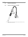
TheMulti-parameterTransmitterM400FF,M400PAintrinsicallysafeapparatus,entity/fieldbus
intrinsicallysafeconceptversion,bearsthefollowinglabelmarking:
LabelModelM400FF
2.4.1.3 Control Drawings
Refer to section „16.6ControlDrawings“onPage122.

Transmitter M400 FF 19
© 02/2023 METTLER TOLEDO Transmitter M400 FF
Printed in Switzerland 30 078 302 H
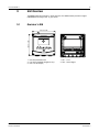
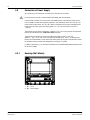
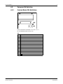
3 Unit Overview
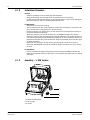
TheM400modelsareavailablein½DINcasesize.TheM400modelsprovideanintegral
IP66/NEMA4Xhousingforwall-orpipemount.
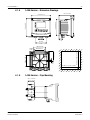
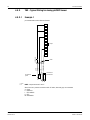
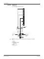
3.1 Overview½DIN
150 mm/5.90"
150 mm/5.90"
M400
EnterInfo
CalMenu
1
2
3
ESC
2
1
1: HardPolycarbonateCase 1: TB1–FF-H1
2: FiveTactile-FeedbackNavigationKeys 2: TB2–SensorSignal
3: Four-lineLCDDisplay

20 Transmitter M400 FF
Transmitter M400 FF © 02/2023 METTLER TOLEDO
30 078 302 H Printed in Switzerland
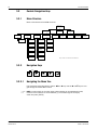
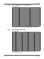
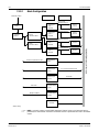
3.2 Control/NavigationKeys
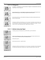
3.2.1 Menu Structure
BelowisthestructureoftheM400menutree:
Measurement
Mode M400 FF
CalMenu Info
Messages ISM Sensor
Info*
Model/Software
Revision
Calibration Data ISM
Diagnostics*
* Only available in combination with ISM sensors
Quick Setup Configure System Service
Set Language
Passwords
Set/Clear
Lockout
Reset
Calibrate
Tech Service
Diagnostics
Set Date & Time
Channel Select Measurement
Alarm/Clean
ISM Setup*
Display
Hold Outputs
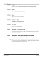
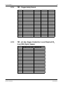
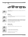
3.2.2 NavigationKeys
Menu CalInfo Enter
ESC
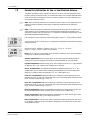
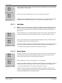
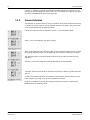
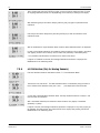
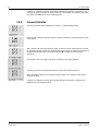
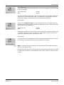
3.2.2.1 Navigating the Menu Tree
EnterthedesiredmainMenubranchwiththe c or keys.Usethe and .keystonavi-
gatethroughtheselectedMenubranch.
h NOTE:Inordertobackuponemenupage,withoutescapingtothemeasurementmode,
movethecursorundertheUPArrowcharacter(u)atthebottomrightofthedisplay
screenandpress[ENTER].
Page is loading ...
Page is loading ...
Page is loading ...
Page is loading ...
Page is loading ...
Page is loading ...
Page is loading ...
Page is loading ...
Page is loading ...
Page is loading ...
Page is loading ...
Page is loading ...
Page is loading ...
Page is loading ...
Page is loading ...
Page is loading ...
Page is loading ...
Page is loading ...
Page is loading ...
Page is loading ...
Page is loading ...
Page is loading ...
Page is loading ...
Page is loading ...
Page is loading ...
Page is loading ...
Page is loading ...
Page is loading ...
Page is loading ...
Page is loading ...
Page is loading ...
Page is loading ...
Page is loading ...
Page is loading ...
Page is loading ...
Page is loading ...
Page is loading ...
Page is loading ...
Page is loading ...
Page is loading ...
Page is loading ...
Page is loading ...
Page is loading ...
Page is loading ...
Page is loading ...
Page is loading ...
Page is loading ...
Page is loading ...
Page is loading ...
Page is loading ...
Page is loading ...
Page is loading ...
Page is loading ...
Page is loading ...
Page is loading ...
Page is loading ...
Page is loading ...
Page is loading ...
Page is loading ...
Page is loading ...
Page is loading ...
Page is loading ...
Page is loading ...
Page is loading ...
Page is loading ...
Page is loading ...
Page is loading ...
Page is loading ...
Page is loading ...
Page is loading ...
Page is loading ...
Page is loading ...
Page is loading ...
Page is loading ...
Page is loading ...
Page is loading ...
Page is loading ...
Page is loading ...
Page is loading ...
Page is loading ...
Page is loading ...
Page is loading ...
Page is loading ...
Page is loading ...
Page is loading ...
Page is loading ...
Page is loading ...
Page is loading ...
Page is loading ...
Page is loading ...
Page is loading ...
Page is loading ...
Page is loading ...
Page is loading ...
Page is loading ...
Page is loading ...
Page is loading ...
Page is loading ...
Page is loading ...
Page is loading ...
Page is loading ...
Page is loading ...
Page is loading ...
Page is loading ...
Page is loading ...
Page is loading ...
Page is loading ...
Page is loading ...
Page is loading ...
Page is loading ...
Page is loading ...
Page is loading ...
Page is loading ...
Page is loading ...
Page is loading ...
Page is loading ...
Page is loading ...
Page is loading ...
Page is loading ...
Page is loading ...
-
 1
1
-
 2
2
-
 3
3
-
 4
4
-
 5
5
-
 6
6
-
 7
7
-
 8
8
-
 9
9
-
 10
10
-
 11
11
-
 12
12
-
 13
13
-
 14
14
-
 15
15
-
 16
16
-
 17
17
-
 18
18
-
 19
19
-
 20
20
-
 21
21
-
 22
22
-
 23
23
-
 24
24
-
 25
25
-
 26
26
-
 27
27
-
 28
28
-
 29
29
-
 30
30
-
 31
31
-
 32
32
-
 33
33
-
 34
34
-
 35
35
-
 36
36
-
 37
37
-
 38
38
-
 39
39
-
 40
40
-
 41
41
-
 42
42
-
 43
43
-
 44
44
-
 45
45
-
 46
46
-
 47
47
-
 48
48
-
 49
49
-
 50
50
-
 51
51
-
 52
52
-
 53
53
-
 54
54
-
 55
55
-
 56
56
-
 57
57
-
 58
58
-
 59
59
-
 60
60
-
 61
61
-
 62
62
-
 63
63
-
 64
64
-
 65
65
-
 66
66
-
 67
67
-
 68
68
-
 69
69
-
 70
70
-
 71
71
-
 72
72
-
 73
73
-
 74
74
-
 75
75
-
 76
76
-
 77
77
-
 78
78
-
 79
79
-
 80
80
-
 81
81
-
 82
82
-
 83
83
-
 84
84
-
 85
85
-
 86
86
-
 87
87
-
 88
88
-
 89
89
-
 90
90
-
 91
91
-
 92
92
-
 93
93
-
 94
94
-
 95
95
-
 96
96
-
 97
97
-
 98
98
-
 99
99
-
 100
100
-
 101
101
-
 102
102
-
 103
103
-
 104
104
-
 105
105
-
 106
106
-
 107
107
-
 108
108
-
 109
109
-
 110
110
-
 111
111
-
 112
112
-
 113
113
-
 114
114
-
 115
115
-
 116
116
-
 117
117
-
 118
118
-
 119
119
-
 120
120
-
 121
121
-
 122
122
-
 123
123
-
 124
124
-
 125
125
-
 126
126
-
 127
127
-
 128
128
-
 129
129
-
 130
130
-
 131
131
-
 132
132
-
 133
133
-
 134
134
-
 135
135
-
 136
136
-
 137
137
-
 138
138
-
 139
139
-
 140
140


Mettler Toledo Multi-parameter Transmitter M400 FF Operating instructions
- Category
- Measuring, testing & control
- Type
- Operating instructions
Ask a question and I''ll find the answer in the document
Finding information in a document is now easier with AI