Siemens RAA Series Technical Instructions

Category
Thermostats
Type
Technical Instructions

Siemens RAA Series: A versatile room thermostat designed for precise temperature control in commercial and light industrial buildings. With its two-point control algorithm, it efficiently manages heating and cooling systems based on user-defined setpoints. The RAA Series thermostats are compatible with various HVAC equipment, including zone valves, gas burners, fans, and pumps, providing flexible temperature management solutions.

Siemens RAA Series: A versatile room thermostat designed for precise temperature control in commercial and light industrial buildings. With its two-point control algorithm, it efficiently manages heating and cooling systems based on user-defined setpoints. The RAA Series thermostats are compatible with various HVAC equipment, including zone valves, gas burners, fans, and pumps, providing flexible temperature management solutions.

Siemens Industry, Inc.
RAA Series
Technical Instructions
Document No. 155-519P25
ET RAA-1
March 2, 2007
Room Thermostats
RAA20…
Description Two-wire, gas diaphragm-based room thermostats for use in heating and/or cooling
only (two-pipe) systems.
Features Two-point control algorithm (on-off)
24 to 120 Vac, 277 Vac operating voltage
Two mounting styles: electrical wall box or drywall
Wall plate adapter (ARG70) included with electrical wall box mount styles
Dual setpoint temperature scale (RAA20..) or tamperproof (concealed) setpoint
(RAA10…)
Product Numbers See Table 1.
Accessory ARG70 Wall box adapter
Application Typically used in:
Schools
Public buildings
Storage rooms
Maintenance rooms
Temporary heat for building construction
Used in commercial and light industrial buildings in conjunction with:
Zone valves
Gas, fuel burners
Fans
Pumps
Technical Instructions RAA Series Room Thermostats
Document Number 155-519P25
March 2, 2007
Page 2 Siemens Industry, Inc.
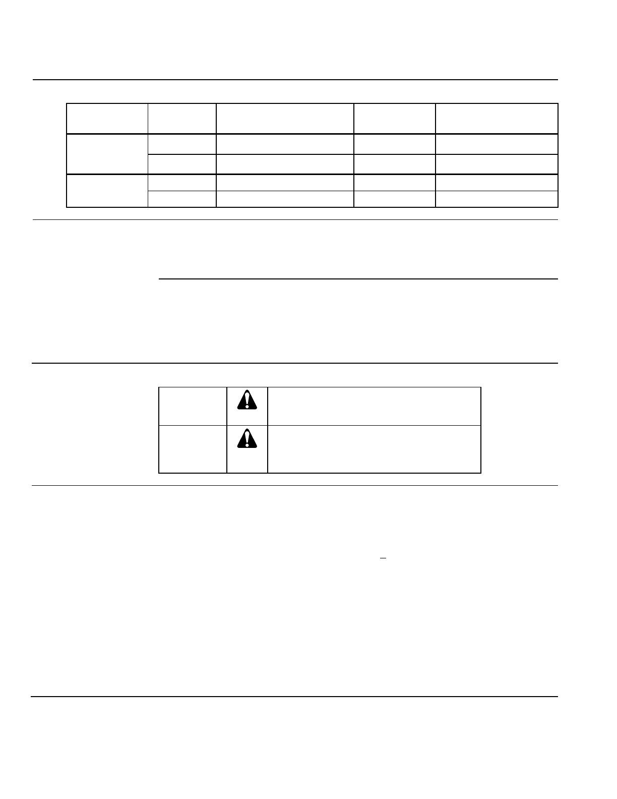
Table 1. Product Numbers.
Mounting Style Product
Number Control Switch Scale
Electrical Wall
Box (with wall
box adapter)
RAA10CW Heating only or cooling only None Celsius (concealed)
RAA20UW Heating only or cooling only None Fahrenheit and Celsius
Drywall1 RAA10C Heating only or cooling only None Celsius (concealed)
RAA20U Heating only or cooling only None Fahrenheit and Celsius
Operation The room thermostat is based on a two-wire, gas membrane technology.
When the room temperature falls below the selected setpoint, the thermostat closes the
heating contact. If the room temperature is over the selected setpoint, the cooling
contact is closed.
Adjustments A rotating setpoint adjuster inside the thermostat can select the required temperature.
RAA10… No adjustments can be made outside the thermostat. The cover must be
removed to adjust setpoint.
RAA20… High and low setpoint limit stops can be engaged to limit temperature
range.
Warning/Caution Notations
WARNING:
Personal injury, or loss of life may occur if
you do not perform a procedure as specified.
CAUTION:
Equipment damage, or loss of data may
occur if you do not follow a procedure as
specified.
Specifications Operating voltage 24 to 120 Vac, 277 Vac
Frequency 50/60 Hz
Setpoint adjustment range 50°F to 85°F (10°C to 30°C)
Setpoint limit stops are adjustable (except RAA10…)
Switching differential (SD) <1.8°F (1°C), fixed
Switch rating 6A RES, 3.5A FLA, 12A LRA
Switch action Single-Pole, Double-Throw (SPDT)
Output Two-position (On/Off)
Weight 5 oz. (0.14 kg)
Dimensions
RAA10… 3.80 × 3.92 × 1.42 inches
(96.4 × 99.6 × 36 mm)
RAA20… 3.80 × 3.92 × 1.68 inches
(96.4 × 99.6 × 42.8 mm)
Color Ivory white
RAA Series Room Thermostats Technical Instructions
Document Number 155-519P25
March 2, 2007
Siemens Industry, Inc. Page 3
Ambient Conditions
Operation
Temperature 32°F to 122°F (0°C to 50°C)
Relative humidity <95%
Transport/Storage
Temperature 4°F to 122°F (20°C to 50°C)
Relative humidity <95%
Housing
Material Plastic
Enclosure rating NEMA1
Bellows Environmentally-friendly gas
Wiring
Screw terminals for wires of 2 × 16 AWG
or 1 × 14 AWG
minimum 20 AWG
Agency Certification
Conforms to CE requirements
UL listed to 873 (E35918)
cUL listed to Canadian standard
C22.2 No. 24-93
Table 2. Control Valves.
Part Number Description Technical Instructions
SFA71U 24V NC
155-321P25
SFA11U 120V NC
SFA208U/25 208V NC
SFA277U/25 277V NC
STA71 24V NC 155-709
599 Series Zone
Valves Two-way
Three-way 155-320P25
Technical Instructions RAA Series Room Thermostats
Document Number 155-519P25
March 2, 2007
Page 4 Siemens Industry, Inc.
Mounting Locate the unit where the air temperature can be sensed as accurately as possible. Do
not mount in direct sunlight or near other heat or refrigeration sources.
Mounting height is approximately 60 inches (1.5 m) above the floor.
The unit can be fitted to most commercially available recessed conduit boxes or directly
on the wall.
Figure 1. Recommended Mounting Locations.
(Dimensions in Inches)
WARNING:
1. This unit can be installed by authorized personnel only.
2. The unit must be de-energized and the operating voltage
checked before opening.
An ARG70 wall plate adapter (provided with electrical wall box mount models) must
be used to mount to a 2 × 4-inch or 4 × 4-inch electrical wall box.
An ARG70 wall plate adapter must be used to meet UL and cUL requirements.
The thermostat must be mounted on a flat wall.
All local electrical regulations must be complied with.
If there are radiator valves in the room, set them to their fully open position.
Setpoint Limit Stops
Adjustment To set limit stops, remove gray tabs located on the setpoint knob and position high and
low stops around the perimeter of knob as required. Each position on the setpoint dial is
1.8°F.
Installation
Required Tools
Small, flat-blade screwdriver
1/4-inch drill bit
Drill motor
Small mallet
Pencil
RAA Series Room Thermostats Technical Instructions
Document Number 155-519P25
March 2, 2007
Siemens Industry, Inc. Page 5
Drywall Mounting 1. Loosen the two screws at the bottom of thermostat.
2. Lift the bottom of the thermostat cover from the thermostat base and push up to
remove cover.
3. Remove sub-base from back of thermostat.
4. Using the sub-base (packed with thermostat) as a template, mark the hole locations
with a pencil.
5. Drill two 1/4-inch diameter holes for plastic wall anchors (provided).
6. Using a mallet, tap in the plastic wall anchors flush with wall.
7. Pull the wiring through the opening in the upper portion of the sub-base.
8. Level the mounting plate.
9. Using the two wood screws provided, fasten sub-base to wall. Thermostat is not
position sensitive.
10. Pull the wiring through the thermostat housing.
11. Position thermostat housing over the two mounting lugs located at the top of the
sub-base, and press down on cover until bottom lugs snap in place.
12. Terminate wires per wiring instructions on the inside of thermostat cover.
Optional: To set limit stops, remove gray tabs located on the setpoint knob and
position high and low stops around perimeter of knob as required. See Figure 2.
Figure 2. Setpoint Limit Stops.
13. Insert the top of the thermostat cover into the slots located on the top of the
thermostat and press down.
14. Tighten the two screws at the bottom of the thermostat.
The installation is now complete.
Technical Instructions RAA Series Room Thermostats
Document Number 155-519P25
March 2, 2007
Page 6 Siemens Industry, Inc.
4 × 4-inch Electrical Wall
Box Mounting An ARG70 wall plate adapter is required to mount an RAA… thermostat to a 4 × 4-inch
electrical wall box. The ARG70 wall plate adapter is included with electrical wall box
mount models.
1. Loosen the two screws at the bottom of thermostat.
2. Lift the bottom of the thermostat cover from the thermostat base and push up to
remove cover.
3. Using the four screws provided, fasten wall box adapter (3) to plaster ring (2),
supplied by others.
4. Pull wires through plaster ring (2).
5. Flex adapter mask (4) and snap in place inside wall box adapter (3).
6. Fasten sub-base (5), included with thermostat, to wall box adapter assembly (3)
and (4) with one No. 4-24 × 5/8-inch long screw (provided with the thermostat) at
the bottom only.
7. Pull wires through the sub-base (5).
8. Clip thermostat base (6) at the top of the sub-base and snap the bottom in place.
9. Level the thermostat base and fasten at the top with a No. 4-24 × 5/8-inch long
screw.
10. Follow Drywall Mounting Steps 10 through 16.
The installation is now complete.
Figure 3. 4 × 4-inch Electrical Wall Box Installation.
1 Electrical wall box
2 Plaster ring
3 Wall box adapter *
4 Adapter mask *
* Included with ARG70
5 Sub-base
6 Thermostat base
7 Thermostat cover
RAA Series Room Thermostats Technical Instructions
Document Number 155-519P25
March 2, 2007
Siemens Industry, Inc. Page 7
2 × 4-inch Electrical Wall
Box Mounting An ARG70 wall plate adapter is required to mount an RAA… thermostat to a 2 × 4-inch
electrical wall box. The ARG70 wall plate adapter is included with electrical wall box
mount models.
1. Loosen the two screws at the bottom of thermostat.
2. Lift the bottom of the thermostat cover from the thermostat base and push up to
remove cover.
3. Using the two screws provided, fasten wall box adapter (3) to plaster ring (2),
supplied by others.
4. Pull wires through plaster ring (2).
5. Flex adapter mask (4) and snap in place inside wall box adapter (3).
6. Fasten sub-base (5), included with thermostat, to wall box adapter assembly (3)
and (4) with one No. 4-24 × 5/8-inch long screw (provided with the thermostat)
at the bottom only.
7. Pull wires through the sub-base (5).
8. Clip thermostat base (6) at the top of the sub-base and snap the bottom in
place.
9. Level the thermostat base and fasten at the top with a No. 4-24 × 5/8-inch long
screw.
10. Follow Drywall Mounting Steps 10 through 16.
The installation is now complete.
Figure 4. 2 × 4-inch Electrical Wall Box Installation.
1 Electrical wall box
3 Wall box adapter *
4 Adapter mask *
* Included with ARG70
5 Sub-base
6 Thermostat base
7 Thermostat cover
Technical Instructions RAA Series Room Thermostats
Document Number 155-519P25
March 2, 2007
Page 8 Siemens Industry, Inc.
Maintenance The room thermostat is completely maintenance-free. If inoperable, replace entire unit.
WARNING:
High voltage. Disconnect power before servicing. Metal part is not
grounded.
Wiring Diagrams
Heating Mode
Cooling Mode
D2 Cooling device
L Operating voltage
N Neutral
N1 Room thermostat
T Thermal switch
W Heating control output
Y Cooling control output
Figure 5. RAA10…and RAA20… Wiring.
Operating Diagrams
Heating Mode
Cooling Mode
T Room temperature
SD Switching differential
SP Room temperature
setpoint
W Heating output signal
Y Cooling output signal
Figure 6. RAA10… and RAA20 Operating.
Dimensions
Dimensions in inches
(millimeters)
Figure 7. RAA10… Unit.
RAA Series Room Thermostats Technical Instructions
Document Number 155-519P25
March 2, 2007
Information in this publication is based on current specifications. The company reserves the right to make changes in specifications and models as
design improvements are introduced. Product or company names mentioned herein may be the trademarks of their respective owners.
© 2007 Siemens Industry, Inc.
Siemens Industry, Inc.
Building Technologies Division
1000 Deerfield Parkway
Buffalo Grove, IL 60089
+ 1 847-215-1000
Your feedback is important to us. If you have
comments about this document, please send them
toSBT_technical.edit[email protected]
Document No. 155-519P25
Printed in the USA
Page 9
Dimensions,
Continued
Dimensions in inches
(millimeters)
Figure 8. RAA20… Unit.
Figure 9. Base Plate.
Figure 10. ARG70.
  • Page 1 1
  • Page 2 2
  • Page 3 3
  • Page 4 4
  • Page 5 5
  • Page 6 6
  • Page 7 7
  • Page 8 8
  • Page 9 9

Siemens RAA Series Technical Instructions

Category
Thermostats
Type
Technical Instructions

Siemens RAA Series: A versatile room thermostat designed for precise temperature control in commercial and light industrial buildings. With its two-point control algorithm, it efficiently manages heating and cooling systems based on user-defined setpoints. The RAA Series thermostats are compatible with various HVAC equipment, including zone valves, gas burners, fans, and pumps, providing flexible temperature management solutions.

Ask a question and I''ll find the answer in the document

Finding information in a document is now easier with AI