Page is loading ...
NOT FOR REPRODUCTION

2
Table of Contents:
Identifying Your Unit............................................................ 3
Intended Use......................................................................... 3
Initial Setup............................................................................3
General Setup.................................................................. 3
Features and Controls..........................................................4
Engine Pull Starter........................................................... 4
Throttle Lever................................................................... 4
Drive Handle.....................................................................4
Direction Shifter................................................................ 4
Forward Handle................................................................ 5
Reverse Handle................................................................6
Blade Lever...................................................................... 6
Free Wheel Lever.............................................................6
Operation............................................................................... 8
Starting the Engine...........................................................8
Cutting Operation............................................................. 8
Shutting Down the Unit.................................................... 8
Pushing the Unit by Hand................................................ 8
Maintenance Procedures..................................................... 9
Clearing a Clogged Deck................................................. 9
Inspecting and Sharpening the Blade.............................. 9
Replacing the Blade....................................................... 10
Replacing the Drive Belt................................................ 10
Replacing the Drive Belt................................................ 11
Adjusting Drive Cable Tension.......................................12
Adjusting Drive Cable Tension.......................................12
Replacing the Blade Belt................................................12
Replacing the Blade Belt................................................13
Adjusting the Blade Belt Tension................................... 14
Periodic Maintenance......................................................... 16
Troubleshooting.................................................................. 16
Specifications...................................................................... 17
NOT FOR REPRODUCTION
3
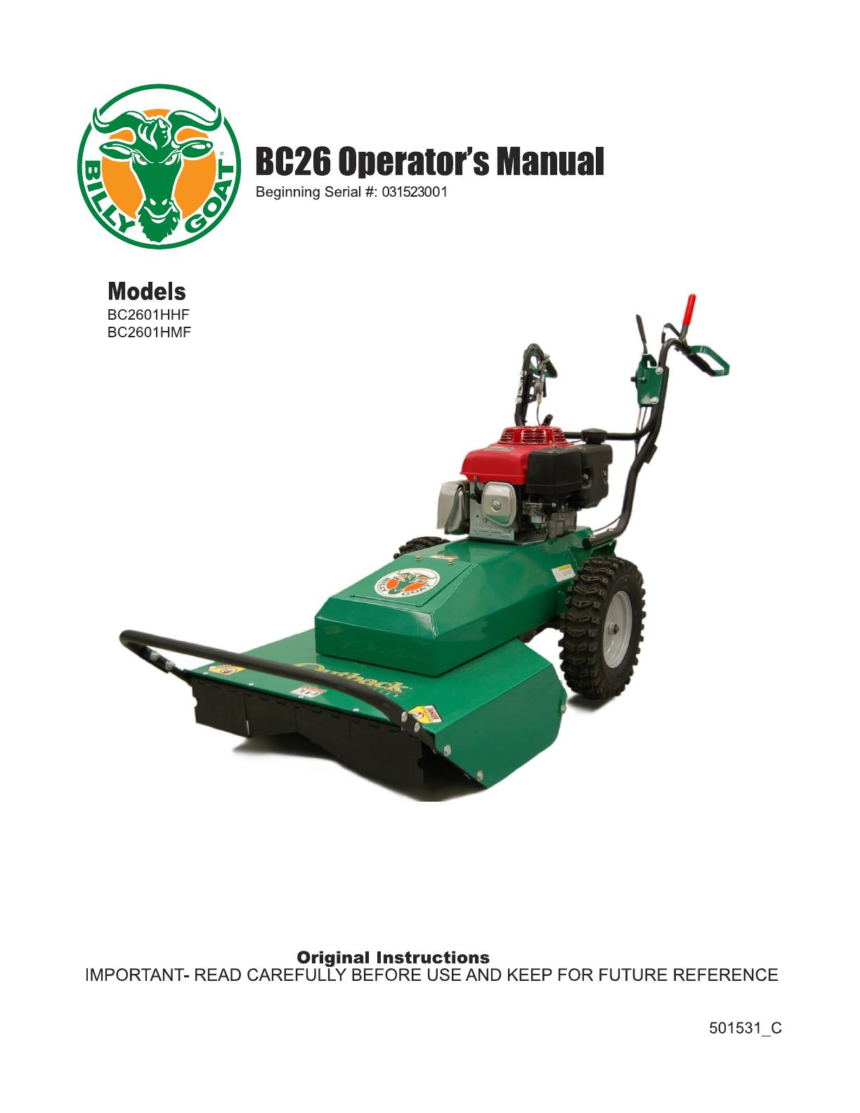
Identifying Your Unit
Thank you for purchasing this quality piece of outdoor
power equipment. Before operation, please note the
product Identification Tag (A, Figure 1) which is found at the
operator's position, below the handlebars.
1
Record your model number, serial number, and engine model
and serial numbers in the space provided for easy access.
PRODUCT REFERENCE DATA
Unit Model Number:
Unit Serial Number:
Dealer Name:
Date Purchased:
ENGINE REFERENCE DATA
Engine Make:
Engine Model:
Engine Type/
Specifications:
Engine Code/Serial
Number:
When contacting your authorized service dealer for
replacement parts, service, or information you MUST have
these numbers.
Note:For the location of the engine identification numbers,
refer to engine owner's manual.
Intended Use
This machine may only be utilized for the purpose for which
it was designed. This machine is designed to cut brush. Be
sure that all operators of this equipment are trained in general
machine use and safety.
Initial Setup
General Setup
Your unit was shipped in a box or wooden crate. Remove the
unit from the carton and remove all packaging.
1. Verify all cables are secured to the handlebars with metal
conduit clamps and/or plastic cable ties.
2. Check the engine oil level. Fill if necessary.
3. Check the engine fuel level and fill if necessary.
4. Electric models only: Secure the battery in the battery
plate. Hook one side of the strap into the hole, then
stretch the strap across the top of the battery and hook
the opposite side into the opposing hole on the plate. Be
sure the battery is secure, then connect terminals.
5. Read the General Safety Manual to familiarize yourself
with safety topics related to the unit and prepare yourself
for operation.
NOT FOR REPRODUCTION
4
Features and Controls
Engine Pull Starter
Note:Check engine oil and fuel levels before attempting to
start the engine! Add oil and/or fuel, if necessary.
Fits: Non-Electric Units.
Pull the starter rope to start the engine. Pull the starter cord
slowly until resistance is felt. Then, pull the cord rapidly to
avoid kickback.
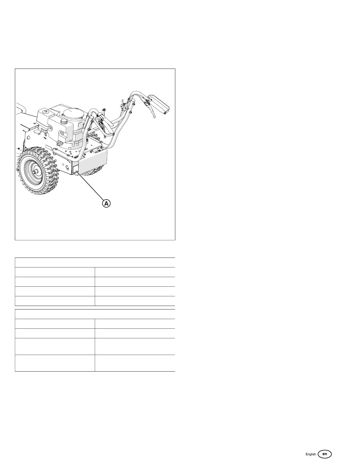
Throttle Lever
The throttle lever (A, Figure 2) increases the engine speed.
Before starting the engine, depress the throttle lever. Depress
the lever completely (A, Figure 3) to reach top engine speed.
2
3
Drive Handle
Fits: Mechanical drive models
Squeeze the mechanical drive handle (A, Figure 4) to engage
the unit in motion. Before engaging the drive lever, use the
direction shifter to select forward or reverse motion.
4
Direction Shifter
Fits: Mechanical drive models
NOT FOR REPRODUCTION

5
The direction shifter allows the operator to change drive
direction and gear. Reference the direction shifter decal
(Figure 5)to select from reverse, neutral, or forward motion.
Forward motion provides first, second, or third gear options.
To select direction, move the direction shifter lever up or
down. The lever will "click" into place. Figure 6 shows the
direction shifter in forward motion. Figure 7 shows the
direction shifter in reverse motion.
5
6
7
Forward Handle
Fits: Hydro-drive units
Use the forward handle (A, Figure 8) on the right to maneuver
the unit in a forward direction. Slowly squeeze the handle,
while stepping forward to achieve forward motion. To stop
forward motion, let go of the handle completely.
8
NOT FOR REPRODUCTION

6
Reverse Handle
Fits: Hydro-drive units
Use the reverse handle (A, Figure 9) on the left to maneuver
the unit in a reverse direction. Slowly squeeze the handle,
while walking backwards to achieve reverse motion. To stop
reverse motion, let go of the handle completely.
9
Blade Lever
The blade lever engages the blade, causing the blade to spin
and cut brush. To engage the blade, completely depress the
blade lever (A, Figure 10).To disengage the blade, release
the blade lever (A, Figure 11).
10
11
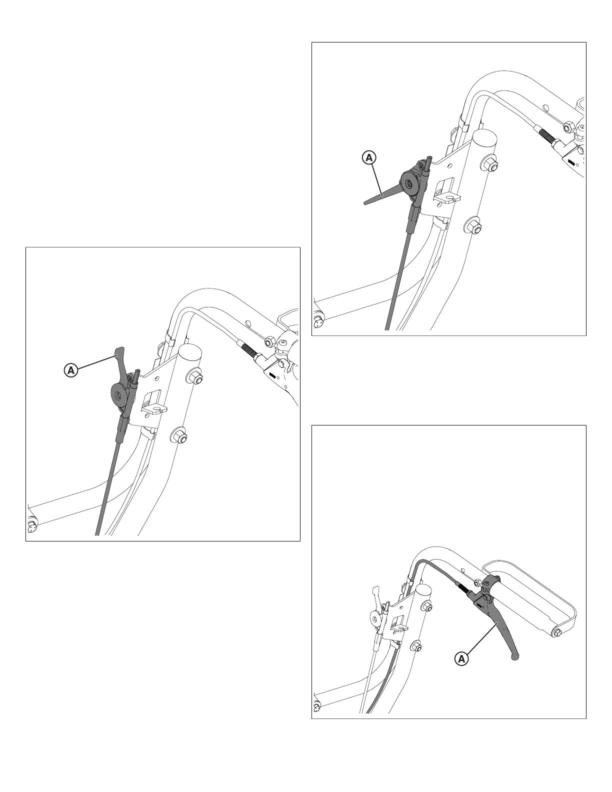
Free Wheel Lever
Fits: Hydro-drive models
Use the Free Wheel Lever (A, Figure 12) to push the unit by
hand. Pull out the lever to disengage drive-enabled motion.
This will allow you to transport and push the unit by hand.
Push the lever in to engage drive-enabled motion. Refer to
decal 501504 (Figure 13)for more information.
NOT FOR REPRODUCTION
7
12
13
NOT FOR REPRODUCTION

8
Operation
Starting the Engine
CAUTION
Check engine oil and fuel levels before operating machine!
Add oil and/or fuel, if necessary.
DANGER
Do not start equipment with drive levers or blade lever
engaged!
1. Place the unit on a level, firm surface that is free of rocks
or other debris.
2. Depress the throttle lever. See the Throttle Control
section for more information.
3. Under cold conditions, engage the engine's choke lever.
4. Start the engine. For manual starter engines: Pull
the starter rope slowly until resistance is felt, then pull
the cord rapidly to avoid kickback. For electric starter
engines: Turn key ignition right until the engine starts. Do
not crank for more than ten (10) seconds at a time if the
engine does not immediately start.
5. Disengage the choke, if necessary.
Cutting Operation
1. Press blade lever down to engage the blade. Allow
the blade to spin up to normal operating speed before
engaging drive controls.
2. Begin vehicle drive. For mechanical models, use a
combination of the Drive Lever and the Direction Shifter
to maneuver the unit. For hydro-drive models, use a
combination of the forward (right) and reverse (left) levers
to maneuver the unit.
Best performance is achieved when cutting in dry
conditions. The quality of cut is related to ground speed.
Cutting should be done at low ground speed under most
conditions, especially for thick brush. Fast speeds should
only be used in areas where brush is thin and short. If the
quality of cut is not to your satisfaction, slow down!
Shutting Down the Unit
1. Release the blade lever to stop blade activity.
2. Release the drive lever to cease motion and park the unit.
3. Move the throttle lever up to the slowest position possible.
4. Electric units: Turn the engine key switch to the "OFF"
position.
Pushing the Unit by Hand
1. Release the blade lever to stop cutting activity. Release
the drive lever to stop motion. Mechanical-Drive
models: Place the direction shifter into the N (neutral)
position. See the Direction Shiftersection for more
information.
2. Shut down the unit. Mechanical-drive models can now be
pushed by hand.
3. Hydro-Drive models: Locate the free wheel lever. See
the Free Wheel Leversection for more information. Pull
out the free wheel lever to disengage the transaxle. You
will now be able to push hydro-drive models unit by hand.
NOT FOR REPRODUCTION

9
Maintenance Procedures
Clearing a Clogged Deck
DANGER
The blade is sharp! To avoid injury, always wear heavy-
duty gloves when performing maintenance on the cutting
deck.
1. Park the unit on a flat, level surface. Turn off the engine
and disconnect the spark plug wire.
2. Lift the unit so that the underside can be safely accessed.
CAUTION
The unit is heavy! Be sure the unit is properly supported
before performing maintenance.
3. Locate and clear the clog from the cutting deck. Be
mindful of the blade!
Inspecting and Sharpening the Blade
1. Follow instructions listed in the Replacing the Blade
section to remove the blade.
CAUTION
Laceration hazard. The blade is sharp! Always wear
heavy-duty gloves when handling or working near the
blade.
2. Inspect the blade. Remove any dried grass, branches, or
other debris. Discard the blade if any bends, cracks, or
other damage is observed.
3. If the blade cutting edge is not sharp or has nicks,
sharpen the cutting edge.
CAUTION
Thrown object and fire hazard. Grinding the blade throws
sparks and fine metal particles that are capable of igniting
gasoline and other flammable vapors, and can injure
unprotected eyes. Be sure all flammable materials are
cleared from the area where grinding will occur. Always
wear safety glasses or goggles when grinding the blade.
4. Use a grinder, hand file, or electric blade sharpener to
sharpen the cutting edge. To ensure balance, remove an
equal amount of material from the cutting edge of each
end of the blade. Be sure to maintain a cutting edge angle
(A, Figure 14) of 30 degrees.
14
5. Be sure the blade is balanced before installing. Clamp
a nail in a bench vise. Hang the blade on the nail, and
position the blade horizontally as shown in Figure 15.
CAUTION
An unbalanced blade can create excessive vibration and
damage to the unit. Be sure the blade is balanced before
installing!
15
6. Check the balance of the blade. If either end of the blade
moves downward, the end that moves downward is
heavier than the other end. Sharpen the heavy end until
balance is achieved.
7. Repeat the process until the mower blade remains in the
horizontal, level position. Reinstall the blade.
NOT FOR REPRODUCTION

10
Replacing the Blade
DANGER
The blade is sharp! To avoid injury, always wear heavy-
duty gloves when inspecting or replacing the blade.
1. Park the unit on a flat, level surface. Turn off the engine
and disconnect the spark plug wire.
2. Lift the unit so that the underside and blade can be safely
accessed.
DANGER
The unit is heavy! Be sure the unit is properly supported
before performing maintenance.
3. Block the blade to prevent it from rotating during removal.
4. Remove the blade bolt (A, Figure 16) and friction washer
(B), then remove the blade (C).
16
5. Install the replacement blade. Secure it with a new friction
washer and new blade bolt. Torque the blade bolt to 40 ft-
lb.
6. Reconnect the spark plug wire.
Replacing the Drive Belt
Fits: Hydro-drive models.
CAUTION
The drive belt is under constant tension by the drive idler
arm. Stored energy may be present. Use caution when
performing maintenance.
1. Park the unit on a flat, level surface. Turn off the engine
and disconnect the spark plug wire.
2. Safely lift and support the unit to allow access to the
underside of the unit.
3. To access the belt, remove the lower belt guard (A,
Figure 17). First, loosen and remove the two nuts (B).
Then loosen and remove the four screws (C) that secure
the belt guard.
17
4. To release the tension on the drive belt (A, Figure 18),
detach the drive belt extension spring (B) from the spring
bracket (C). Figure 18 displays the drive system when
viewed from below.
NOT FOR REPRODUCTION

11
18
5. Walk the drive belt (A) off of the clutch (D).
CAUTION
The belt and clutch can create a pinch-point. Use caution
when performing maintenance.
6. Slip the belt (A) off the transaxle (E) pulley. The transaxle
pulley is hidden above the transaxle in Figure 18.
7. Install a new drive belt. Reverse steps 4-6. Be sure
the new drive belt is seated properly in the clutch and
transaxle pulley. Be sure the belt does not bend over the
transaxle fan blades. Be sure the blade belt (F) remains
correctly installed.
8. Reinstall the lower belt guard.
Replacing the Drive Belt
Fits: Mechanical drive models.
CAUTION
The drive belt is under constant tension by the drive idler
arm. Stored energy may be present. Use caution when
performing maintenance.
1. Park the unit on a flat, level surface. Turn off the engine
and disconnect the spark plug wire.
2. Safely lift and support the unit to allow access to the
underside of the unit.
3. To access the belt, uninstall the lower belt guard (A,
Figure 19). Loosen and remove the four screws (B) that
secure the belt guard.
19
4. To release the tension on the drive belt (A, Figure 20),
detach the drive belt spring (B) from the spring bolt (C).
Figure 20 displays the drive system when viewed from
below.
20
5. Walk the drive belt (A) off the clutch (D).
NOT FOR REPRODUCTION
12
CAUTION
The belt and clutch can create a pinch-point. Use caution
when performing maintenance.
6. Slip the belt off the transaxle (E) pulley. The transaxle
pulley is hidden above the transaxle in Figure 20.
7. Install a new drive belt. Reverse steps 4-6. Be sure
the new drive belt is seated properly in the clutch and
transaxle pulley. Be sure the belt does not bend over the
transaxle fan blades. Be sure the blade belt (F) remains
correctly installed.
8. Reinstall the lower belt guard.
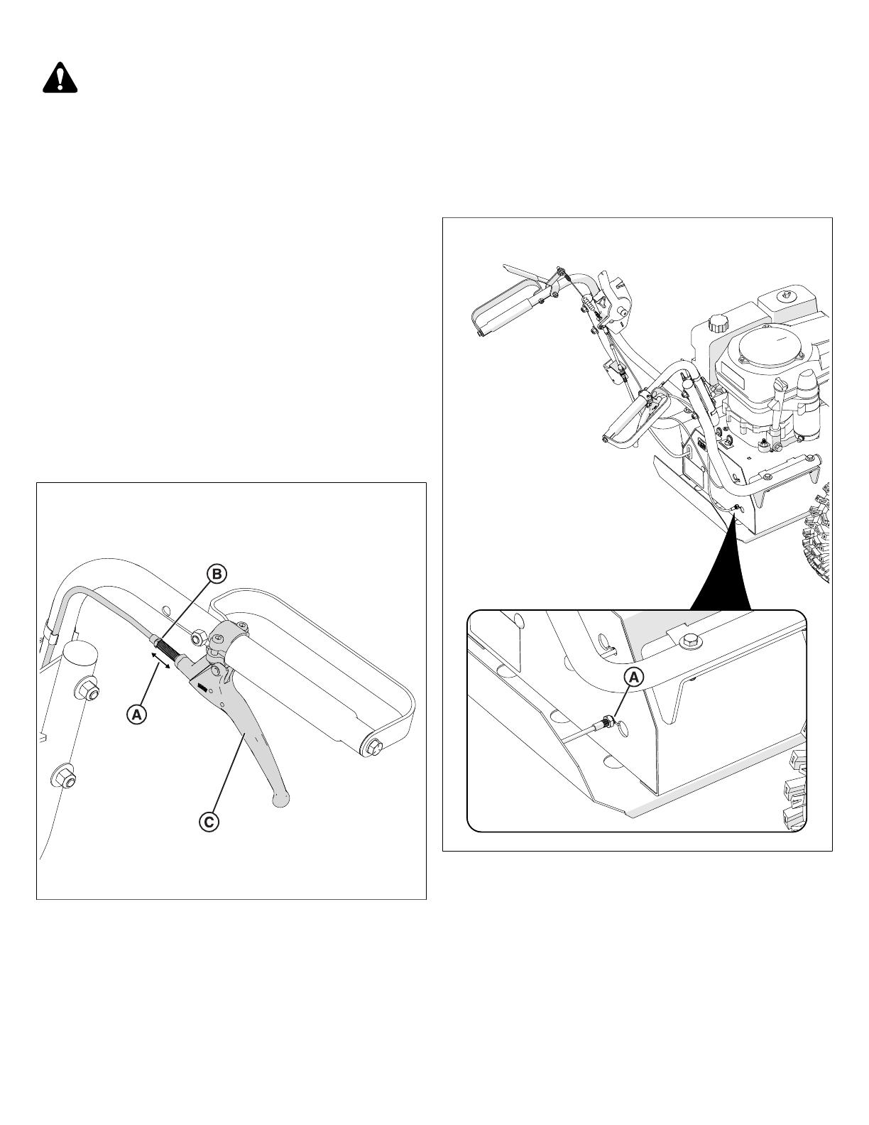
Adjusting Drive Cable Tension
Fits: Hydro-drive models.
1. Park the unit on a flat, level surface. Turn off the engine
and disconnect the spark plug wire.
2. To adjust cable tension, adjust the barrel length (A,
Figure 21). To adjust the barrel length, loosen the barrel
nut (B) by hand. Engage the drive lever (C) to desired
tension.
21
Note:Do not apply excessive tension to the cables. This can
lead to damage or premature failure.
3. Tighten the barrel nut.
4. Apply lithium grease to the slot in the lever where the
cable sits. This step will prevent damage and premature
failure.
Adjusting Drive Cable Tension
Fits: Mechanical-drive models.
1. Park the unit on a flat, level surface. Turn off the engine
and disconnect the spark plug wire.
2. Locate the drive cable adjustment nut (A, Figure 22).
Tighten or loosen the nut to adjust drive cable tension. Be
sure to leave enough slack in the cable to allow the drive
lever to engage.
22
3. Reconnect the spark plug wire. Start the unit and engage
the drive handle to test cable adjustment.
If the drive lever continues to slip or operates incorrectly,
shut down the unit, and do not operate the unit until
proper repair has been performed.Contact an authorized
service dealer.
Replacing the Blade Belt
Fits: Hydro-drive models.
1. Park the unit on a flat, level surface. Turn off the engine
and disconnect the spark plug wire.
NOT FOR REPRODUCTION
13
2. Refer to the Replacing the Drive Beltsection to remove
the drive belt.
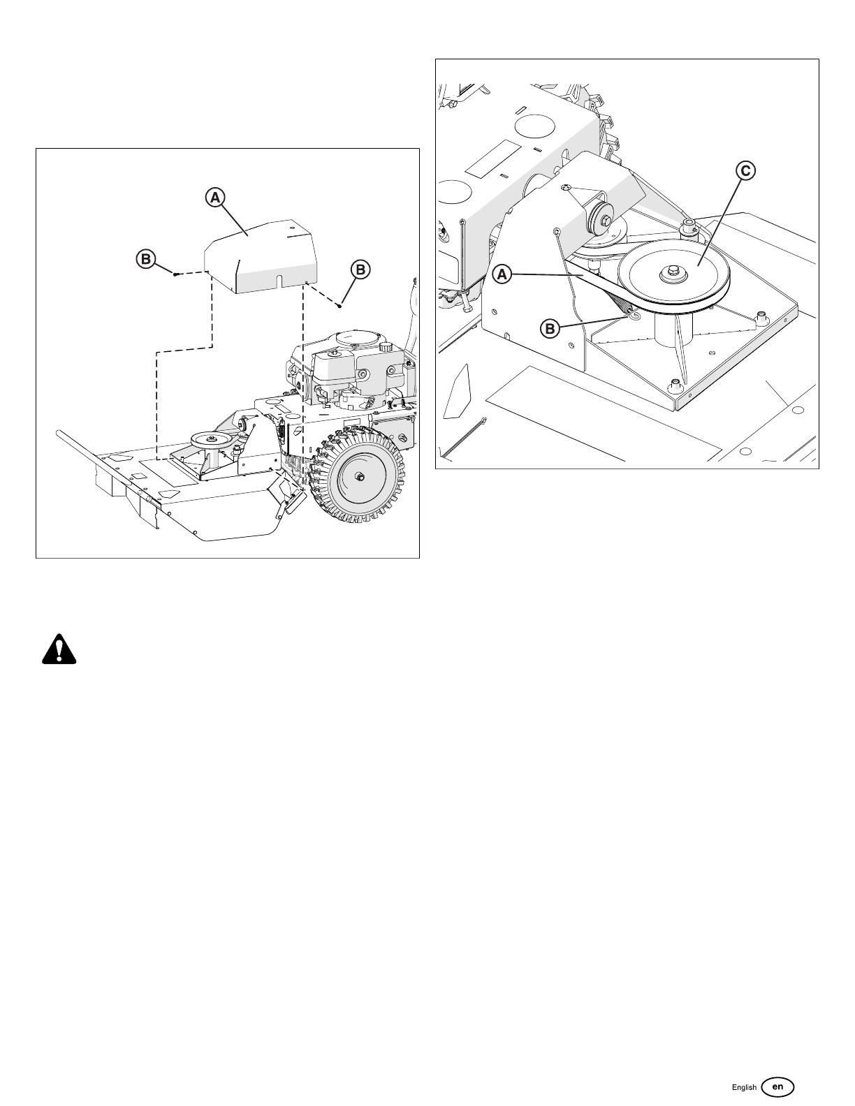
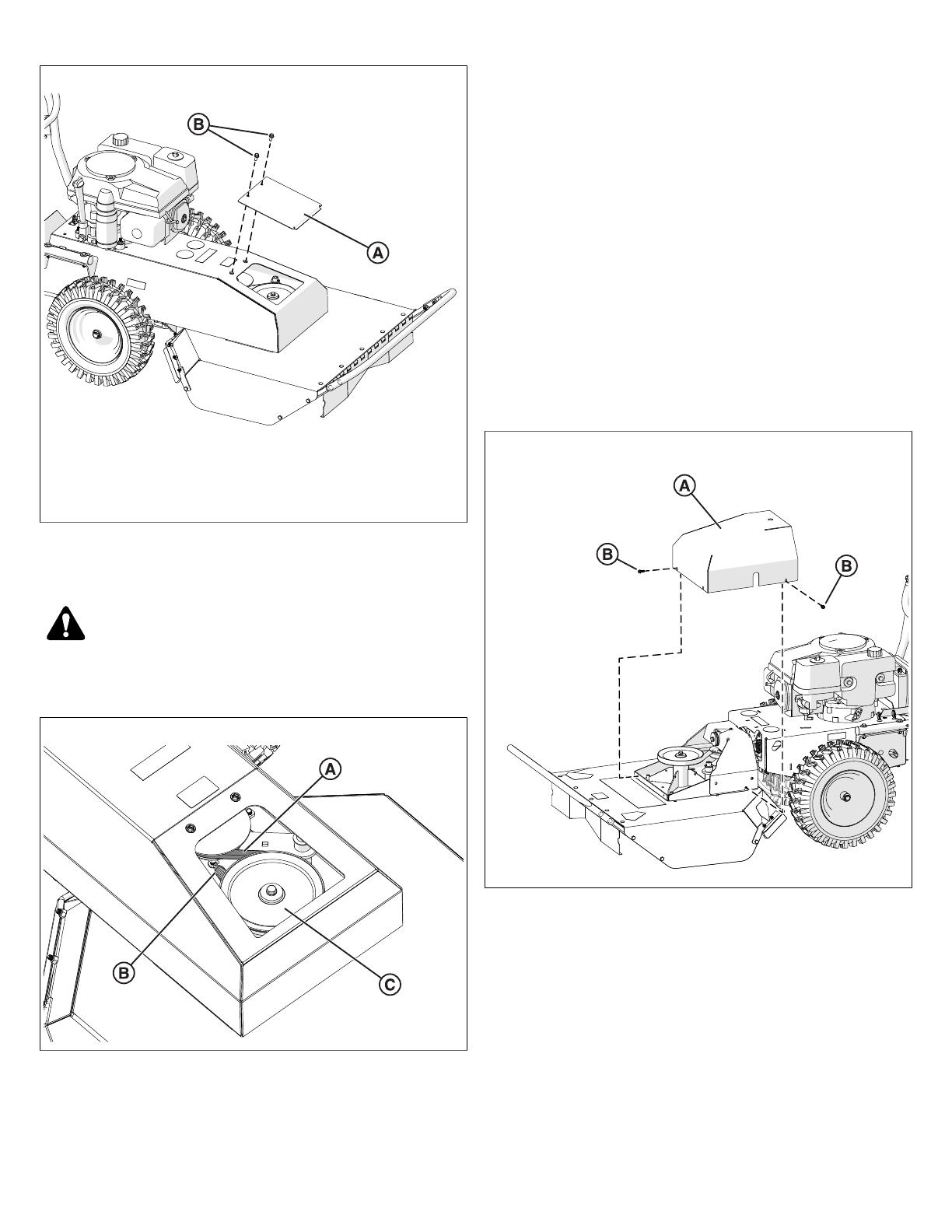
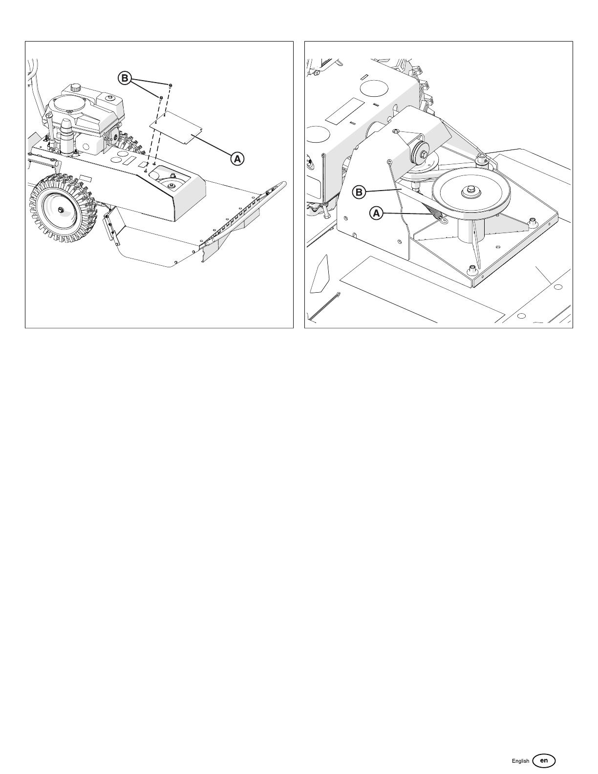
3. Remove the deck cover (A, Figure 23). Loosen and
remove the four screws (B) that secure the deck cover,
and then remove the deck cover.
23
4. Relieve tension on the blade belt (A, Figure 24).
Disconnect the blade extension spring (B) from its
position under the blade pulley (C).
CAUTION
The belt is under constant tension by the idler arm. Stored
energy may be present. Use caution when performing
maintenance.
24
5. With blade belt tension relieved, walk the blade belt (A)
off of the blade pulley (C). Direct the belt towards the
back of the unit.
6. Return to the back of the unit. Slip the belt off of the
clutch, remove the belt from the unit completely.
7. Install a new blade belt. First, install the blade belt onto
the clutch. Then install the blade belt onto the blade
pulley. Reinstall the blade extension spring. Reinstall the
deck cover.
8. Reinstall the drive belt. Reinstall the lower belt guard.
Reconnect the spark plug wire.
Replacing the Blade Belt
Fits: Mechanical drive models
1. Park the unit on a flat, level surface. Turn off the engine
and disconnect the spark plug wire.
2. Refer to the Replacing the Drive Belt section to remove
the drive belt.
3. Uninstall the deck cover (A, Figure 25). Loosen and
remove the two screws (B) that secure the deck cover,
and then remove the deck cover.
NOT FOR REPRODUCTION
14
25
4. Release tension on the blade belt (A, Figure 26).
Disconnect the blade extension spring (B) from its
position under the blade pulley (C).
CAUTION
The belt is under constant tension by the idler arm. Stored
energy may be present. Use caution when performing
maintenance.
26
5. With blade belt tension relieved, walk the blade belt (A)
off of the blade pulley (C). Direct the belt towards the
back of the unit.
6. Return to the back of the unit. Slip the belt off of the
clutch, remove the belt from the unit completely.
7. Install a new blade belt. First, install the blade belt onto
the clutch. Then install the blade belt onto the idler pulley
and blade pulley. Reinstall the blade extension spring.
Reinstall the deck cover.
8. Reinstall the drive belt. Reinstall the lower belt guard.
Reconnect the spark plug wire.
Adjusting the Blade Belt Tension
Note:The blade belt is under constant tension by the blade
idler arm. Stored energy may be present. Use caution.
1. Park the unit on a flat, level surface. Turn off the engine
and disconnect the spark plug wire.
2. To access the blade belt, remove the deck cover (A,
Figure 27 and 28). Loosen and remove the four screws
(B) securing the deck cover to the deck. Set aside to
reinstall after adjusting belt tension.Determine if tension
problem is due to the the blade idler spring or the blade
belt itself.
27
NOT FOR REPRODUCTION
15
28
3. If the blade belt tension is too loose, inspect the condition
of the blade idler spring (A, Figure 29). Replace the
spring if necessary to increase tension on the blade belt.
29
4. Inspect the condition of the belt (B, Figure 29). Replace
the blade belt if worn or damaged. See Replacing the
Blade Belt for more information.
5. Reinstall the deck cover. See Step 2.
6. Reconnect the spark plug wire.
7. Check belt tension by operating the unit under the same
conditions that caused belt slippage. If belt continues to
slip, contact an authorized service dealer.
NOT FOR REPRODUCTION

16
Periodic Maintenance
Maintenance
Operation
Every Use Every 25 Hrs Every 50 Hrs Every 100 Hrs
Inspect for worn or damaged
parts.
X
Check for excessive vibration. X
Inspect for loose parts. X
Sharpen the blade. X
Inspect belts for wear. X
Lubricate throttle control cable
and linkage.
X
Check blade clutch cable
tension.
X
Apply anti-seize compound to
rear axles.
X
Replace blade drive and
transaxle drive belts.
X
Troubleshooting
Problem Possible Cause Corrective Action
Engine will not start. Throttle is set to Slow/Stop position.
Out of gasoline.
Old or contaminated gasoline.
Spark plug wire disconnected.
Dirty air filter.
Move throttle to "FAST" position.
Fill gas tank.
Drain gas tank and fill with fresh gasoline.
Connect spark plug wire.
Clean or replace air filter.
Starter does not turn (Electric units only). Battery low or dead.
Battery cable disconnected or corroded.
Defective starter switch or wiring harness.
Defective starter.
Charge or replace battery.
Clean and secure battery terminals.
Replace starter switch or wiring harness.
Replace starter.
Will not cut or cutting performance is poor. Blade cable tension incorrect.
Dull blade.
Clogged deck.
Excessive debris built up on or blocking blade.
Engine RPM set too low.
Adjust blade cable tension.
Sharpen or replace blade.
Unclog deck.
Clear debris from blade area.
Check engine RPM.
Abnormal vibrations. Blade loose or out of balance.
Engine loose.
Blade drive belt worn.
Check blade for tightness. Rebalance if necessary.
Check engine mounting bolts.
Replace blade drive belt.
Belt slips or smokes. Belt tension too low.
Belt worn or stretched.
Pulleys worn or damaged.
Adjust belt tension.
Replace belt.
Replace pulleys.
Clutch slips or squeals. Drivecable tension too low.
Clutch worn or damaged.
Adjust the drive cable tension.
Replace worn or defective clutch assembly parts.
Blade brake will not engage. Inadequate slack in clutch cable.
Clutch worn or damaged.
Adjust clutch cable.
Replace clutch/brake assembly.
Transaxle will not engage. Drive lever(s) not engaging clutch.
Drive cable(s) defective.
Drive belt worn or broken.
Adjust drive cable(s).
Replace cable(s).
Replace drive belt.
Transaxle will not disengage. Drive cable out of adjustment. Adjust drive cable.
NOT FOR REPRODUCTION

17
Problem Possible Cause Corrective Action
Engine will not turn over. Defective blade clutch.
Engine problem.
Replace clutch.
Contact an authorized servicing dealer for your
engine.
Specifications
Engine Specifications
Brand Honda
Model # GXV390UT1-DABG
HP 10.1 HP (7.6 KW)
Oil Capacity 1.2 qt. (1.14 L)
Fuel Capacity 2.22 qt (2.1 L)
Dimensions
Length 81.5" (207 cm)
Width 30.75" (78.1 cm)
Height 44" (111.8 cm)
Weight 367 lbs (166 Kg)
NOT FOR REPRODUCTION

NOT FOR REPRODUCTION
/