Wenglor C50 Operating Instructions Manual
- Category
- Software
- Type
- Operating Instructions Manual
This manual is also suitable for

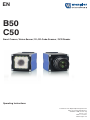
B50
C50
Smart Camera / Vision-Sensor / 1D-/2D-Code-Scanner / OCR Reader
Operating Instructions
Translation of the Original Operating Instruction
Subject to change without notice
Available as PDF version only
Version: 1.4.0
Status: 17.02.2017
www.wenglor.com
EN

EN
2Table of Contents
Table of Contents
1. Use for Intended Purpose ........................................................................................ 8
2. Safety Precautions ................................................................................................... 8
3. Approvals and protection class ............................................................................... 8
4. Technical Data .......................................................................................................... 9
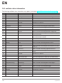
4.1. Available weQube Sensor Types ............................................................................................................ 9
4.1.1. Sensors with Monochrome Image Chip ...................................................................................... 9
4.1.3. Sensors with Color Image Chip and Autofocus ......................................................................... 10
4.2. List of Technical Data ............................................................................................................................11
4.3. Connection Diagrams ...........................................................................................................................12
4.4. Housing Dimensions .............................................................................................................................13
4.5. Control Panel .........................................................................................................................................13
5. Installation and Connection ................................................................................... 14
5.1. General Installation Instructions............................................................................................................14
5.2. System Overview ...................................................................................................................................14
5.3. Accessory Products ..............................................................................................................................16
5.3.1. Matching Mounting Technology ................................................................................................ 16
5.3.2. Matching Connection Technology ............................................................................................. 16
5.3.2.1. Connector Cables .........................................................................................................16
5.3.2.2. Connection Cable .........................................................................................................16
5.3.2.3. Connecting Module .......................................................................................................17
5.3.2.4. Interface Cable .............................................................................................................. 17
5.4. LED Display ........................................................................................................................................... 18
5.5.1. Cable Connection ....................................................................................................................... 19
5.5.2. Sensor Network Settings ............................................................................................................19
5.5.2.1. Adjusting Sensor Network Settings Manually .............................................................. 19
5.5.2.2. Adjusting Sensor Network Settings Automatically via DHCP Server ........................... 20
5.5.2.3. Initial Start-Up of the weQube at a Controller ............................................................... 20
5.6. Default Settings ..................................................................................................................................... 21
6. Functions Description, OLED Display ................................................................... 22
6.1. Run ........................................................................................................................................................23
6.2. Teach-In .................................................................................................................................................24
6.3. Teach+ ..................................................................................................................................................24
6.4. Display ..................................................................................................................................................25
6.4.1. Intensity ......................................................................................................................................25
6.4.2. Mode ...........................................................................................................................................26
6.5. Assistant ................................................................................................................................................ 27
6.6. Projects ..................................................................................................................................................28
6.6.1. Current Project ...........................................................................................................................28
6.6.2. Loading a Project .......................................................................................................................28
6.6.3. Selecting the Start Project .......................................................................................................... 29
6.7. Configuration .........................................................................................................................................29
6.8. Interface .................................................................................................................................................29
6.8.1. Serial interface ............................................................................................................................29
6.8.2. Ethernet ......................................................................................................................................30
6.8.2.1. DHCP.............................................................................................................................30
6.8.2.2. IP Address ..................................................................................................................... 30

3
Smart Camera / Vision-Sensor / 1D-/2D-Code-Scanner / OCR Reader
6.8.2.3. MAC Address ................................................................................................................ 31
6.8.2.4. Network Reset ............................................................................................................... 31
6.9. Language .............................................................................................................................................. 31
6.10. Info ....................................................................................................................................................... 32
6.11. Restart ................................................................................................................................................. 32
6.12. Reset.................................................................................................................................................... 32
6.13. Password ............................................................................................................................................. 33
6.14. Status Information ............................................................................................................................... 33
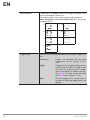
7. Installing and Updating the Software .....................................................................34
7.1. Minimum Requirements ........................................................................................................................ 34
7.2. Installation Procedure ........................................................................................................................... 34
7.3. Updating the Software .......................................................................................................................... 34
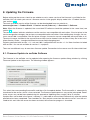
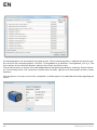
8. Updating the Firmware ............................................................................................35
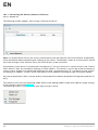
8.1. Firmware Update via weQube Software ............................................................................................... 35
8.2. Firmware Update via FTP-Interface ...................................................................................................... 37
9. License Management ..............................................................................................38
10. General Layout of weQube Software ...................................................................39
10.1. Initial Window ...................................................................................................................................... 39
10.1.1. Connecting the Sensor (Connect to Device) ........................................................................... 40
10.1.1.1. Device list .................................................................................................................... 40
10.1.1.2. The Search Network Window ..................................................................................... 41
10.1.1.3. The File Manager ........................................................................................................ 43
10.1.1.4. Properties .................................................................................................................... 44
10.1.2. Open ......................................................................................................................................... 46
10.1.2.1. Project File .................................................................................................................. 46
10.1.2.2. Teach+ File ................................................................................................................. 46
10.1.2.3. Template Files ............................................................................................................. 46
10.1.3. Demo Projects .......................................................................................................................... 47
10.2. User Interface ...................................................................................................................................... 48
10.2.1. Common Layout Features ........................................................................................................ 49
10.2.2. The Menu Bar ........................................................................................................................... 50
10.2.2.1. File ............................................................................................................................... 50
10.2.2.2.User accounts .............................................................................................................. 50
10.2.2.3. Settings ....................................................................................................................... 53
10.2.2.4. View ............................................................................................................................. 54
10.2.2.5. Help ............................................................................................................................. 55
10.2.2.6. User Mode ................................................................................................................... 55
10.2.2.7. Closing the Project ...................................................................................................... 55
10.2.3. Modifiable Windows and Areas ................................................................................................ 56
10.2.3.1. Navigation Area, Settings/Results, Function Field ..................................................... 56
10.2.3.2. Image Container Viewer .............................................................................................. 57
10.2.3.3. Profile .......................................................................................................................... 59
10.2.3.4. Histogram .................................................................................................................... 59
10.2.3.5. Toolbox ....................................................................................................................... 60
10.2.3.6. Network Tools ............................................................................................................. 60
10.2.3.7. Process Times ............................................................................................................. 61
10.2.3.8. Project Tools ............................................................................................................... 61
10.2.3.9. Module Tools .............................................................................................................. 64
10.2.3.10. Online Data Monitoring Module ................................................................................ 64

EN
4Table of Contents
10.2.4. Image Area ...............................................................................................................................66
10.2.5. The Status Bar .......................................................................................................................... 66
11. Software Module .................................................................................................. 67
11.1. Application Module .............................................................................................................................67
11.1.1. Overview ................................................................................................................................... 67
11.1.2. Setting Parameters ................................................................................................................... 67
11.2. Camera Device Module .......................................................................................................................68
11.2.1. Overview ................................................................................................................................... 68
11.2.2. Setting Parameters ................................................................................................................... 68
11.2.2.1.White Balancing ...........................................................................................................72
11.2.3. Configuration ............................................................................................................................ 72
11.2.3.1. Image Sensor ..............................................................................................................73
11.2.3.2. Readout Box Sub-Module ...........................................................................................73
11.2.3.3. Auto-Focus Box ...........................................................................................................74
11.3. Module Localizer ................................................................................................................................. 75
11.3.1. Overview ................................................................................................................................... 75
11.3.2. Settings .....................................................................................................................................76
11.3.3. Configuration ............................................................................................................................ 77
11.3.3.1. Coordinate System .....................................................................................................77
11.3.3.2. Search Box ..................................................................................................................77
11.3.3.3. Teach Image ...............................................................................................................78
11.3.3.4. Teach Box ...................................................................................................................78
11.4. Module Coordinate System ................................................................................................................79
11.4.1. Overview ................................................................................................................................... 79
11.4.2. Settings .....................................................................................................................................80
11.4.3. Configuration ............................................................................................................................ 81
11.4.3.1. Coordinate System .....................................................................................................81
11.4.3.2. Construction Method ..................................................................................................81
11.5. Module Region .................................................................................................................................... 92
11.5.1. Overview ................................................................................................................................... 92
11.5.2. Settings .....................................................................................................................................93
11.5.3. Configuration ............................................................................................................................ 95
11.5.3.1. Region ......................................................................................................................... 95
11.5.3.2. Set ...............................................................................................................................96
11.6. Module Filter ........................................................................................................................................97
11.6.1. Overview ................................................................................................................................... 97
11.6.2. Settings .....................................................................................................................................98
11.6.3. Configuration .......................................................................................................................... 101
11.6.3.1. Output Image ............................................................................................................101
11.7. Module Threshold .............................................................................................................................101
11.7.1. Overview ................................................................................................................................. 101
11.7.2. Settings ...................................................................................................................................102
11.7.2.1.Magic Wand ..............................................................................................................104
11.7.3. Configuration .......................................................................................................................... 105
11.7.3.1. Output Image ............................................................................................................105
11.8. Module Threshold HSV ..................................................................................................................... 106
11.8.1. Overview ................................................................................................................................. 106
11.8.2. Settings ...................................................................................................................................108
11.8.3. Configuration .......................................................................................................................... 109
11.8.3.1. Output Image ............................................................................................................109
11.8.3.2. Hue ............................................................................................................................ 109
11.8.3.3. Value ..........................................................................................................................110

5
Smart Camera / Vision-Sensor / 1D-/2D-Code-Scanner / OCR Reader
11.8.3.4. Saturation .................................................................................................................. 110
11.9. Module Cluster .................................................................................................................................. 110
11.9.1. Overview ................................................................................................................................. 110
11.9.2. Settings ...................................................................................................................................111
11.9.3. Configuration .......................................................................................................................... 112
11.9.3.1. Cluster List.................................................................................................................113
11.10. Module Measure .............................................................................................................................113
11.10.1. Overview ............................................................................................................................... 113
11.10.2. Settings .................................................................................................................................114
11.10.2.1. Find Line ..................................................................................................................115
11.10.2.2. Find Circle ...............................................................................................................117
11.10.2.3. Measure Distance ...................................................................................................119
11.10.2.4. Measure Intersection ...............................................................................................120
11.10.2.5.Measure Segment on Line Sub-Module ..................................................................121
11.10.2.6.Measure Segment on Circle Sub-Module ...............................................................122
11.10.2.7.Measure Segment on Arc Sub-Module ...................................................................123
11.11. Module Code 1D ............................................................................................................................. 125
11.11.1. Overview ............................................................................................................................... 125
11.11.2. Settings .................................................................................................................................125
11.11.3. Configuration ........................................................................................................................ 126
11.11.3.1. Reading List ............................................................................................................126
11.11.3.2. Search Box ..............................................................................................................127
11.11.3.3. Enhanced Parameter ..............................................................................................127
11.12. Module Code 2D ............................................................................................................................. 130
11.12.1. Overview ............................................................................................................................... 130
11.12.2. Settings .................................................................................................................................131
11.12.3. Configuration ........................................................................................................................ 132
11.12.3.1. Reading List Sub-Module .......................................................................................132
11.12.3.2. Search Box ..............................................................................................................134
11.12.4. General settings for all Code Types .....................................................................................135
11.12.5. Data Matrix ECC 200 ............................................................................................................ 136
11.12.6. QR Code ...............................................................................................................................137
11.12.7. PDF417 ................................................................................................................................. 138
11.13. Module Image Comparison ...........................................................................................................139
11.13.1. Overview ............................................................................................................................... 139
11.13.2. Settings .................................................................................................................................139
11.13.3. Configuration ........................................................................................................................ 141
11.13.3.1. Output Image ..........................................................................................................141
11.13.3.2. Reference Image .....................................................................................................142
11.13.3.3. Threshold Image ..................................................................................................... 142
11.14. Modules OCR (optical character reader) ........................................................................................143
11.14.1. Overview ............................................................................................................................... 143
11.14.2. Parameter Settings ............................................................................................................... 143
11.14.3. Configuration ........................................................................................................................ 144
11.14.3.1. Results List .............................................................................................................. 144
11.14.3.2. Segment List ...........................................................................................................144
11.14.3.3. Search Region.........................................................................................................145
11.14.3.4. Find Lines ................................................................................................................145
11.14.3.5. Binarization ..............................................................................................................146
11.14.3.6. Segmentation .......................................................................................................... 147
11.14.3.7. Classification ...........................................................................................................148
11.14.3.8. Insert ........................................................................................................................148

EN
6
11.14.3.9. Teaching Characters In ...........................................................................................149
11.15. OCR-Tip ...........................................................................................................................................150
11.15.1. Basic Character Geometry ................................................................................................... 151
11.15.1.1. Examples .................................................................................................................151
11.15.2. Size of the ROI ......................................................................................................................151
11.15.2.1. Examples .................................................................................................................152
11.15.3. Background .......................................................................................................................... 152
11.15.4. Contrast ................................................................................................................................152
11.15.4.1. Examples .................................................................................................................153
11.16. Pattern Matching Module ................................................................................................................153
11.16.1. Overview ............................................................................................................................... 153
11.16.2. Setting Parameters ............................................................................................................... 153
11.16.3. Configuration ........................................................................................................................ 158
11.16.3.1. Results List Sub-Module .........................................................................................158
11.16.3.2. Search Region Sub-Module ....................................................................................158
11.16.3.3.Taught-In Rectangle .................................................................................................159
11.16.3.4. Contour Model ........................................................................................................159
11.17. Module Match Code ........................................................................................................................160
11.17.1. Overview ............................................................................................................................... 160
11.17.2. Settings .................................................................................................................................161
11.17.2.1. Number Elements ..................................................................................................161
11.18. Module Logic ...................................................................................................................................162
11.18.1. Overview ............................................................................................................................... 162
11.18.2. Settings .................................................................................................................................162
11.19. Module Math ...................................................................................................................................163
11.19.1. Overview ............................................................................................................................... 163
11.19.2. Settings .................................................................................................................................163
11.20. Module Numeric Comparison .........................................................................................................164
11.20.1. Overview ............................................................................................................................... 164
11.20.2. Settings .................................................................................................................................164
11.21. Device IO Unit .................................................................................................................................165
11.21.1. Overview ............................................................................................................................... 165
11.21.2. Settings .................................................................................................................................165
11.21.3. Configuration ........................................................................................................................ 165
11.21.3.1. IO Timings ............................................................................................................... 166
11.21.3.2. Digital I/Os 1 to 6 Sub-Module ................................................................................169
11.21.3.3. Error Handling .........................................................................................................170
11.22. Device Display .................................................................................................................................171
11.22.1. Overview ............................................................................................................................... 171
11.22.2. Settings .................................................................................................................................171
11.22.3. Configuration ........................................................................................................................ 171
11.22.3.1. Text ..........................................................................................................................171
11.22.3.2. Indication .................................................................................................................172
11.22.3.3. Numeric ................................................................................................................... 172
11.22.3.4. Match code .............................................................................................................172
11.22.3.5. Teach .......................................................................................................................173
11.22.4. Error Handling ......................................................................................................................173
11.23. Device Indicator ..............................................................................................................................174
11.23.1. Overview ............................................................................................................................... 174
11.23.2. Settings .................................................................................................................................174
11.23.3. Error Handling ......................................................................................................................174
11.24. Device Communication ...................................................................................................................175
Table of Contents

7
Smart Camera / Vision-Sensor / 1D-/2D-Code-Scanner / OCR Reader
11.24.1. Overview ............................................................................................................................... 175
11.24.2. Settings .................................................................................................................................175
11.24.3. Configuration ........................................................................................................................ 175
11.24.3.1. RS-232 .....................................................................................................................176
11.24.3.2. Industrial Ethernet ................................................................................................... 177
11.24.3.3. UDP .........................................................................................................................179
11.24.3.4. FTP or SD Card ....................................................................................................... 180
11.24.4. Error Handling ......................................................................................................................181
11.25. Module Statistics ............................................................................................................................. 182
11.25.1. Overview ............................................................................................................................... 182
11.25.2. Settings in the Statistics Module .......................................................................................... 182
11.25.3. Configuration ....................................................................................................................... 183
11.25.3.1. Channel # 1 ............................................................................................................183
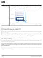
12. Project Change via Digital I/O ........................................................................... 184
12.1. Software Settings ..............................................................................................................................184
12.2. Procedure ..........................................................................................................................................185
13. Network Settings ................................................................................................ 185
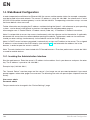
14. Web-Based Configuration .................................................................................. 186
14.1. Invoking the Administration Interface ...............................................................................................186
14.2. Page Layout ......................................................................................................................................187
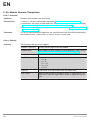
14.3. Device, General .................................................................................................................................187
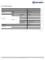
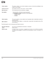
14.4. Device Settings .................................................................................................................................189
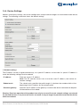
14.5. Projects ..............................................................................................................................................190
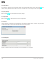
14.6. Teach-In .............................................................................................................................................191
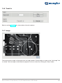
14.7. Image .................................................................................................................................................191
15. Maintenance Instructions .................................................................................. 192
16. Proper Disposal .................................................................................................. 192
17. Exclusion of Liability .......................................................................................... 192
18. Appendix ............................................................................................................. 193
18.1. Setting up an FTP Server at a PC ..................................................................................................... 193
18.2. weQube status information ............................................................................................................... 194
18.3. Coordinate system ............................................................................................................................ 195
18.3.1. Right handed coordinate system ........................................................................................... 195
18.3.2. Image sensor coordinate system ...........................................................................................196
18.3.3. Image coordinate system .......................................................................................................196
18.3.4. Input coordinate system .........................................................................................................197
18.4. Network Settings ............................................................................................................................... 197
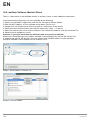
18.5. weQube Software Module States .....................................................................................................198
18.6. weQube Software Module States .....................................................................................................199
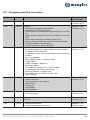
18.7. Changelog operating instructions ....................................................................................................229
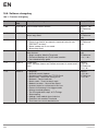
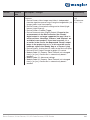
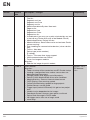
18.8. Software changelog ..........................................................................................................................230
18.8.1. Firmware changelog ...............................................................................................................230
18.8.2. Software changelog ...............................................................................................................235
19. EU Declaration of Conformity ............................................................................ 240

EN
8Use for Intended Purpose
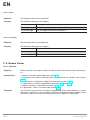
1. Use for Intended Purpose
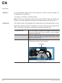
The wenglor weQube is an optoelectronic sensor which is used for contactless inspection of specific objects.
The sensor unites a camera unit, illumination, optics with auto-focus and an analysis module in a single hous-
ing. The sensors work with a CMOS color or monochrome image sensor.
Image processing functions including measurement, object counting, checking for the presence of objects,
pixel comparison, shape analysis and reference image comparison can be configured by means of a PC or
laptop via the integrated Ethernet port. 1D and 2D codes can be read as well.
These image processing functions can be executed in trigger mode operation, as well as during continuous
monitoring, and objects can be detected regardless of position thanks to tracking. Six convertible I/O switching
outputs are available, which can be used as either inputs or outputs. Beyond this, an external lamp can also be
connected to the weQube, and the integrated illumination can be partially or completely switched off.
2. Safety Precautions
• These instructions are an integral part of the product and must be kept on hand for the entire duration of its
service life.
• Read the operating instructions carefully before using the product.
• This sensor is not suitable for safety applications.
• Installation, initial start-up and maintenance of the product should only be carried out by qualified personnel.
• Protect the sensor against mechanical influences.
• Tampering with or modifying the product is impermissible.
• Protect the sensor against contamination during initial start-up.
• The mounting screws must have a thread engagement length of 5 to 7 mm.
3. Approvals and protection class

9
Smart Camera / Vision-Sensor / 1D-/2D-Code-Scanner / OCR Reader
4. Technical Data
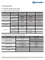
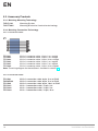
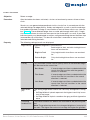
4.1. Available weQube Sensor Types
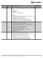
4.1.1. Sensors with Monochrome Image Chip
Sensor type Light
Connection White Light IR Red Light
weQube Vision
Ethernet
B50S002 B50S003 -
B50S005 B50S006 -
Industrial Ethernet
B50S101 B50S102 -
B50S104 B50S105 -
weQube Decode Ethernet C50C001 C50C002 C50C003
Industrial Ethernet C50C100 C50C101 C50C102
weQube Ethernet B50M002 B50M003 B50M004
Industrial Ethernet B50M101 B50M102 B50M104
weQube OCR
Ethernet B50R001 - -
Industrial Ethernet B50R100 - -
Ethernet - B50R002 -
Industrial Ethernet - B50R101 -
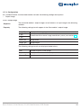
4.1.2. Sensors with monochrome image chip and C-mount
Sensor type Connection Monochrome
weQube Vision
Ethernet B50S012
B50S014
Industrial Ethernet B50S111
B50S113
weQube Decode Ethernet C50C011
Industrial Ethernet C50C110
weQube OCR Ethernet B50R011
Industrial Ethernet B50R110
weQube Ethernet B50M012
Industrial Ethernet B50M111

EN
10 Technical Data
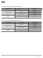
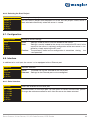
4.1.3. Sensors with Color Image Chip and Autofocus
Sensor type Light
Connection White light
weQube Vision
Ethernet B50S001
B50S004
Industrial Ethernet B50S100
B50S103
weQube Ethernet B50M001
Industrial Ethernet B50M100
4.1.4. Sensors with color image chip and C mount
Sensor type Connection Monochrome
weQube Vision
Ethernet B50S011
B50S013
Industrial Ethernet B50S110
B50S112
weQube Ethernet B50M011
Industrial Ethernet B50M110

11
Smart Camera / Vision-Sensor / 1D-/2D-Code-Scanner / OCR Reader
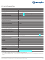
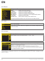
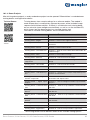
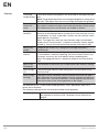
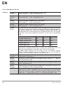
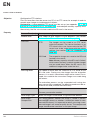
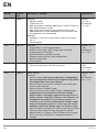
4.2. List of Technical Data
Optical Characteristics
Working range ≥ 20 mm (weQube with auto-focus)
Resolution 736 px × 480 px
Field of vision See “Range of Vision Table”
Image chip See section 4.1 on available sensor types
Type of light See section 4.1 on available sensor types
Refresh rate (monochrome) ≤ 25 Hz
Refresh rate (color) ≤ 15 Hz
Service life 100,000 hours
Risk group (EN 62471) Free group
Electrical Characteristics
Supply power * 18 to 30 V DC
Current consumption (operating voltage = 24 V) < 200 mA
Response time (monochrome) < 40 ms
Response time (color) < 66 ms
Temperature range –25…55 °C **
Number of digital I/Os 6
Switching output voltage drop < 2.5 V
Switching output switching current 100 mA
Short-circuit proof Yes
Protected against polarity reversal Yes
Overload-proof Yes
Protection class III
Interfaces Ethernet 10/100 Base TX; Ethernet or Profinet (see section 4.1 on avail-
able sensor types)
Mechanical Characteristics
Configuration interface Ethernet port
Housing material Aluminum
Protection IP67
Connector type M12×1, 12-pin
Ethernet connector type M12×1, 8-pin
Configurable as PNP, NPN or push-pull Yes
Can be switched to NC or NO operation Yes
Illumination output Yes
RS-232 interface Yes
General Data
Webserver Yes (all Ethernet and Industrial Ethernet Devices, see section
“4.1. Available weQube Sensor Types”)
* Supply voltage residual ripple may not exceed 10 % (within the specified voltage range).
** –25 °C: Ambient conditions should not result in condensation; avoid the formation of ice on the front panel!
55 °C: Continuous illumination at max. 1 % or flash mode at 100 % brightness with an exposure time of ≤ 5 ms: may affect the service life of the
product.

EN
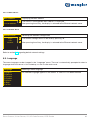
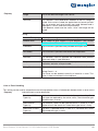
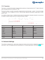
12 Technical Data
Range
of vision
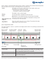
Range of vision table (weQube with auto-focus):
Range of Vision Table:
Working distance 20 mm 100 mm 200 mm 1000 mm 5000 mm
Range of vision 16×12 mm 64×48 mm 120×90 mm 600×450 mm 3000×2250 mm
Range of vision for C mount variant depends on the utilized lens.
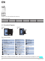
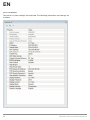
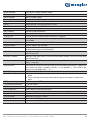
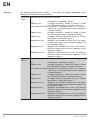
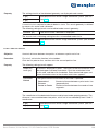
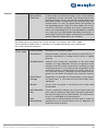
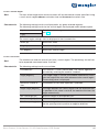
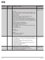
4.3. Connection Diagrams
Plug No. 1 Plug No. 2
002
Explanation of Symbols
Legend
Wire Colors according to
DIN IEC 757
Platinum measuring resistor
not connected
Test Input
Test Input inverted
Trigger Input
Analog Output
Ground for the Analog Output
Block Discharge
Valve Output
Valve Control Output +
Valve Control Output 0 V
Synchronization
Receiver-Line
Emitter-Line
Grounding
Switching Distance Reduction
Ethernet Receive Path
Ethernet Send Path
Interfaces-Bus A(+)/B(–)
Emitted Light disengageable
Magnet activation
Input confirmation
Contactor Monitoring
Encoder A/A (TTL)
Encoder B/B (TTL)
Black
Brown
Red
Orange
Yellow
Green
Blue
Violet
Grey
White
Pink
Green/Yellow
Supply Voltage +
Supply Voltage 0 V
Supply Voltage (AC Voltage)
Switching Output (NO)
Switching Output (NC)
Contamination/Error Output (NO)
Contamination/Error Output (NC)
Input (analog or digital)
Teach Input
Time Delay (activation)
Shielding
Interface Receive Path
Interface Send Path
Ready
Ground
Clock
Output/Input programmable
Power over Ethernet
Safety Input
Safety Output
Signal Output
Ethernet Gigabit bidirect. data line (A-D)
Encoder 0-pulse 0-0 (TTL)
Encoder A
Encoder B
Digital output MIN
Digital output MAX
Digital output OK
Synchronization In
Synchronization OUT
Brightness output
Maintenance
PT
Note: If you use wenglor connection cables, you’ll find the corresponding wiring diagram in section 5.3.2.1.

13
Smart Camera / Vision-Sensor / 1D-/2D-Code-Scanner / OCR Reader
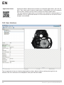
4.4. Housing Dimensions
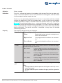
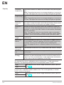
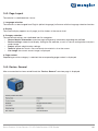
4.5. Control Panel
Up key
Enter key
Down key
Display

EN
14 Installation and Connection
5. Installation and Connection
5.1. General Installation Instructions
All applicable electrical and mechanical regulations, standards and safety precautions must be adhered to
when installing and operating the sensor. The sensor must be protected against mechanical influences. Install
the weQube such that its installation position cannot be inadvertently changed. The wenglor mounting system
is recommended for installing the sensor. It must be assured that the mounting screws have a thread engage-
ment length of 5 to 7 mm.
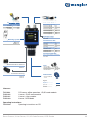
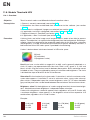
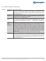
5.2. System Overview
Connector Cables
M12, 12-pin to open end
ZDCL001 (straight) 2 m
ZDCL002 (straight) 5 m
ZDCL003 (straight) 10 m
ZDCL004 (angled) 2 m
ZDCL005 (angled) 5 m
ZDCL006 (angled) 10 m
Connection Cable
M12, 8-pin to RJ45
ZC1V001 2 m
ZAV50R502 5 m
ZC1V002 10 m
Mounting System
ZMBID1202
ZMWZF0001
Alternative Micro SD Card
ZNNG013*
Replacement Disc weQube
ZNNG012
Polarization Filter, Circular
ZNNG004
Connection Cable
M12, 12-pin to M12, 12-pin
ZDCV001 2 m
ZDCV002 5 m
ZDCV003 10 m
M12, 4-pin to M12, 4-pin
BW2SG2V1-2M 2 m
BG2SG2V1-2M 2 m
BG2SG2V3-2M 2 m
Connecting Module
M12, 12-pin to trigger / illumination
ZDCG001
Interface Cable
M12, 12-pin to RS-232
ZDCG002
Legend
Required accessories
Optional accessories
Included in delivery *
Protection Housing
ZNNS001
ZNNS002
Connection Cable
Connector Cables
Mounting System

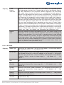
15
Smart Camera / Vision-Sensor / 1D-/2D-Code-Scanner / OCR Reader
Connector Cables
M12, 12-pin to open end
ZDCL001 (straight) 2 m
ZDCL002 (straight) 5 m
ZDCL003 (straight) 10 m
ZDCL004 (angled) 2 m
ZDCL005 (angled) 5 m
ZDCL006 (angled) 10 m
Connection Cable
M12, 8-pin to RJ45
ZC1V001 2 m
ZAV50R502 5 m
ZC1V002 10 m
Mounting System
ZMBID1202
ZMWZF0001
Legend
Required accessories
Optional accessories
Included in delivery *
Lens
LAC9-14-K01 9 mm
LAC25-14-K02 25 mm
LAC35-16-K02 35 mm
Alternative Micro SD Card
ZNNG013*
Protection Housing
ZSZ-02-01
ZSZ-03-01
Illuminations
more Informations
> here
Connection Cable
M12, 12-pin to M12, 12-pin
ZDCV001 2 m
ZDCV002 5 m
ZDCV003 10 m
M12, 4-pin to M12, 4-pin
BW2SG2V1-2M 2 m
BG2SG2V1-2M 2 m
BG2SG2V3-2M 2 m
Connecting Module
M12, 12-pin to trigger / illumination
ZDCG001
Interface Cable
M12, 12-pin to RS-232
ZDCG002
Connection Cable
Connector Cables
Mounting System
Licenses:
ZNN1003 PC license, offline operation, 1D/2D code module
DNNL002 License, 1D/2D code module
DNNL001 License, vision module
DNNL003 License, OCR-Modul
Operating instructions:
ZNNG033 Operating instructions on CD

EN
16 Installation and Connection
5.3. Accessory Products
5.3.1. Matching Mounting Technology
ZMBID1202 Mounting System
ZMWZF0001 Mounting Bracket for illumination technology
5.3.2. Matching Connection Technology
5.3.2.1. Connector Cables
S89
ZDCL001 M12×1 connector cable, 12-pin, 2 m, straight
ZDCL002 M12×1 connector cable, 12-pin, 5 m, straight
ZDCL003 M12×1 connector cable, 12-pin, 10 m, straight
ZDCL004 M12×1 connector cable, 12-pin, 2 m, angled
ZDCL005 M12×1 connector cable, 12-pin, 5 m, angled
ZDCL006 M12×1 connector cable, 12-pin, 10 m, angled
Note: The wiring diagram for the weQube is included in section 4.3.
5.3.2.2. Connection Cable
ZC1V001 M12×1 connection cable, 8-pin, 2 m, to RJ45
ZAV50R502 M12×1 connection cable, 8-pin, 5 m, to RJ45
ZC1V002 M12×1 connection cable, 8-pin, 10 m, to RJ45
ZDCV001 M 12×1 connection cable, 12-pin, 2 m
ZDCV002 M 12×1 connection cable, 12-pin, 5 m
ZDCV003 M 12×1 connection cable, 12-pin, 10 m

17
Smart Camera / Vision-Sensor / 1D-/2D-Code-Scanner / OCR Reader
5.3.2.3. Connecting Module
ZDCG001 M12×1 connecting module, 12-pin to trigger, illumination
5.3.2.4. Interface Cable
ZDCG002 M12×1 interface cable, 12-pin to RS-232

EN
18 Installation and Connection
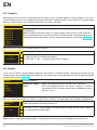
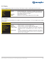
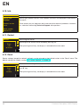
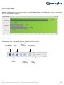
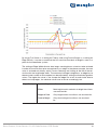
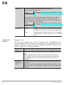
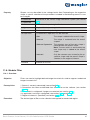
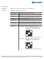
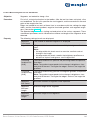
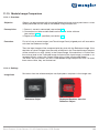
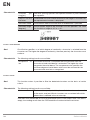
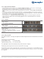
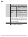
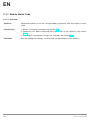
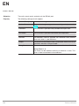
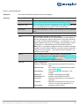
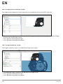
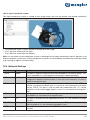
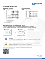
5.4. LED Display
The LEDs on the back of the weQube indicate the following (rear view of the weQube with display at top):
85
84
78
T12
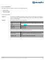
Profinet
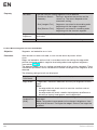
LED Function
84 Communication status
78 Module status
85 Link/act LED
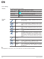
Designation Status Function
CS (communication status)
(only available with Profinet
devices)
Off Connection (AR) established with
controller
Green Protocol not initialized
Red No connection (AR) to controller
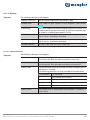
MS (module status)
(only available with Profinet
devices)
Red Error (class: fatal)
Blinking red Detection function, can be switched
on via engineering tool
L/A Green Link available
Blinking green Communication
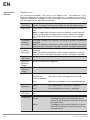
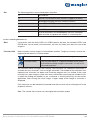
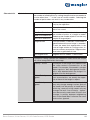
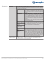
Ethernet/IP
LED Function
84 Network status
78 Module status
85 Link/Act-LED

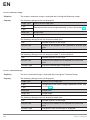
19
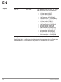
Smart Camera / Vision-Sensor / 1D-/2D-Code-Scanner / OCR Reader
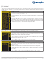
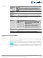
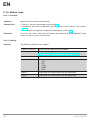
description Status Function
NS (Network status) Off No IP address
green CIP connection
Blinking green IP configured, no CIP connection
red Duplicate IP address
Blinking red CIP connection Timeout
MS (Module status) Off -
green Device works
Blinking green Standby
red Fatal error
Blinking red Device error
L/A Off No Ethernet device connected
green Link available
Blinking green communication
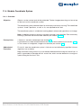
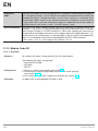
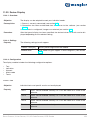
5.5. Initial Start-Up
5.5.1. Cable Connection
Connect the sensor (socket 2) to the Ethernet port at the PC or the controller and connect socket 1 to power
supply (see section 5.2). Power supply must be between 18 and 30 V DC.
Caution: Make sure that the cables have been correctly and securely connected, assuring good physical con-
tact. The sensor’s micro SD card may not be removed during operation. If the micro SD card will be replaced,
disconnect the sensor from power supply first.
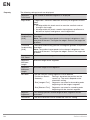
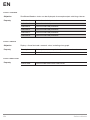
5.5.2. Sensor Network Settings
Upon shipment from the factory, the weQube’s IP address is 192.168.100.1 and its subnet mask is
255.255.255.0.
The following options are available for establishing a connection with the sensor.
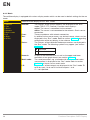
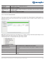
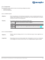
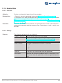
5.5.2.1. Adjusting Sensor Network Settings Manually
In order to be able to connect the sensor to your PC, you have to make sure that the sensor and your PC are
both within the same IP address range.
Ascertain your PC’s IP address and subnet mask to this end.

EN
20 Installation and Connection
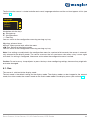
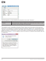
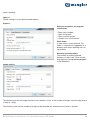
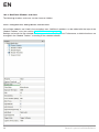
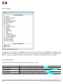
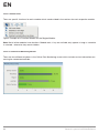
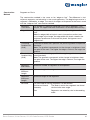
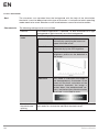
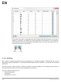
Note: You can ascertain the network settings of your Windows PC by clicking start, entering “cmd” to the
“Search programs and files” line and then pressing the enter key. A command line appears. After entering
“ipconfig” to this line, the PC’s network settings are displayed.
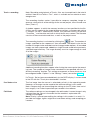
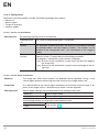
If necessary, change the weQube’s subnet mask, so that it coincides with the PC’s. The subnet mask breaks
the IP address down into a network part (places in the subnet mask occupied by the digits “255”) and a device
part (places in the subnet mask occupied by digits other than “255”).
The network part of the weQube’s IP address must coincide with the network part of the PC’s IP address, and
the device parts of the weQube and the PC must be different.
Example:
The following subnet mask is used for both the PC and the sensor: 255.255.255.0.
If the PC’s IP address is 192.100.100.1, the IP address of the weQube must start as follows: 192.100.100.
The last digit of the IP address must differ from the PC’s last digit, and should only occur once throughout the
network. For example, the following IP address could be used for the weQube: 192.100.100.2.
You can change the sensor’s network settings with the help of weQube software (see section 10.1.1.2).
Alternatively, you can also change the sensor’s IP address at the OLED display (see section 6.8.2).
Caution: It may be necessary to deactivate the PC’s firewall in order to establish connection with the sensor.
Detailed information about deactivating the Windows firewall can be found in the general instructions included
on the weQube product page.
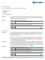
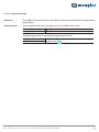
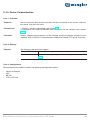
5.5.2.2. Adjusting Sensor Network Settings Automatically via DHCP Server
If the weQube is connected to a DHCP server, activate dynamic host configuration at the sensor either with the
help of weQube software (see section 10.1.1.2) or at the OLED display (see section 6.8.2). A suitable IP address
and subnet mask are assigned to the sensor when it’s restarted.
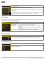
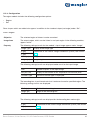
5.5.2.3. Initial Start-Up of the weQube at a Controller
If you want to place the weQube into service at a controller, please complete the following steps:
• Connect weQube to the controller. The display at the sensor is activated when supply voltage is applied.
• Install the associated device-specific electronic description file to the hardware manager (e.g. the GS-
DML for Profinet). The required file can be downloaded from www.wenglor.com Product World
Product search (Order No.) Download. Explanations regarding the electronic description file and its
layout are included in the comprehensive operating instructions in PDF format.
• Help regarding installation of the file to the controller, as well as network planning, can be found in the
help files for the respective controller. wenglor offers descriptions for individual controllers which can be
downloaded from: www.wenglor.com Product World Product search (Order No.) Download.
Caution: When operated with a controller, settings which have been changed via the website or the OLED
display are overwritten by the controller.
Page is loading ...
Page is loading ...
Page is loading ...
Page is loading ...
Page is loading ...
Page is loading ...
Page is loading ...
Page is loading ...
Page is loading ...
Page is loading ...
Page is loading ...
Page is loading ...
Page is loading ...
Page is loading ...
Page is loading ...
Page is loading ...
Page is loading ...
Page is loading ...
Page is loading ...
Page is loading ...
Page is loading ...
Page is loading ...
Page is loading ...
Page is loading ...
Page is loading ...
Page is loading ...
Page is loading ...
Page is loading ...
Page is loading ...
Page is loading ...
Page is loading ...
Page is loading ...
Page is loading ...
Page is loading ...
Page is loading ...
Page is loading ...
Page is loading ...
Page is loading ...
Page is loading ...
Page is loading ...
Page is loading ...
Page is loading ...
Page is loading ...
Page is loading ...
Page is loading ...
Page is loading ...
Page is loading ...
Page is loading ...
Page is loading ...
Page is loading ...
Page is loading ...
Page is loading ...
Page is loading ...
Page is loading ...
Page is loading ...
Page is loading ...
Page is loading ...
Page is loading ...
Page is loading ...
Page is loading ...
Page is loading ...
Page is loading ...
Page is loading ...
Page is loading ...
Page is loading ...
Page is loading ...
Page is loading ...
Page is loading ...
Page is loading ...
Page is loading ...
Page is loading ...
Page is loading ...
Page is loading ...
Page is loading ...
Page is loading ...
Page is loading ...
Page is loading ...
Page is loading ...
Page is loading ...
Page is loading ...
Page is loading ...
Page is loading ...
Page is loading ...
Page is loading ...
Page is loading ...
Page is loading ...
Page is loading ...
Page is loading ...
Page is loading ...
Page is loading ...
Page is loading ...
Page is loading ...
Page is loading ...
Page is loading ...
Page is loading ...
Page is loading ...
Page is loading ...
Page is loading ...
Page is loading ...
Page is loading ...
Page is loading ...
Page is loading ...
Page is loading ...
Page is loading ...
Page is loading ...
Page is loading ...
Page is loading ...
Page is loading ...
Page is loading ...
Page is loading ...
Page is loading ...
Page is loading ...
Page is loading ...
Page is loading ...
Page is loading ...
Page is loading ...
Page is loading ...
Page is loading ...
Page is loading ...
Page is loading ...
Page is loading ...
Page is loading ...
Page is loading ...
Page is loading ...
Page is loading ...
Page is loading ...
Page is loading ...
Page is loading ...
Page is loading ...
Page is loading ...
Page is loading ...
Page is loading ...
Page is loading ...
Page is loading ...
Page is loading ...
Page is loading ...
Page is loading ...
Page is loading ...
Page is loading ...
Page is loading ...
Page is loading ...
Page is loading ...
Page is loading ...
Page is loading ...
Page is loading ...
Page is loading ...
Page is loading ...
Page is loading ...
Page is loading ...
Page is loading ...
Page is loading ...
Page is loading ...
Page is loading ...
Page is loading ...
Page is loading ...
Page is loading ...
Page is loading ...
Page is loading ...
Page is loading ...
Page is loading ...
Page is loading ...
Page is loading ...
Page is loading ...
Page is loading ...
Page is loading ...
Page is loading ...
Page is loading ...
Page is loading ...
Page is loading ...
Page is loading ...
Page is loading ...
Page is loading ...
Page is loading ...
Page is loading ...
Page is loading ...
Page is loading ...
Page is loading ...
Page is loading ...
Page is loading ...
Page is loading ...
Page is loading ...
Page is loading ...
Page is loading ...
Page is loading ...
Page is loading ...
Page is loading ...
Page is loading ...
Page is loading ...
Page is loading ...
Page is loading ...
Page is loading ...
Page is loading ...
Page is loading ...
Page is loading ...
Page is loading ...
Page is loading ...
Page is loading ...
Page is loading ...
Page is loading ...
Page is loading ...
Page is loading ...
Page is loading ...
Page is loading ...
Page is loading ...
Page is loading ...
Page is loading ...
Page is loading ...
Page is loading ...
Page is loading ...
Page is loading ...
Page is loading ...
Page is loading ...
Page is loading ...
Page is loading ...
Page is loading ...
Page is loading ...
Page is loading ...
Page is loading ...
Page is loading ...
Page is loading ...
Page is loading ...
-
 1
1
-
 2
2
-
 3
3
-
 4
4
-
 5
5
-
 6
6
-
 7
7
-
 8
8
-
 9
9
-
 10
10
-
 11
11
-
 12
12
-
 13
13
-
 14
14
-
 15
15
-
 16
16
-
 17
17
-
 18
18
-
 19
19
-
 20
20
-
 21
21
-
 22
22
-
 23
23
-
 24
24
-
 25
25
-
 26
26
-
 27
27
-
 28
28
-
 29
29
-
 30
30
-
 31
31
-
 32
32
-
 33
33
-
 34
34
-
 35
35
-
 36
36
-
 37
37
-
 38
38
-
 39
39
-
 40
40
-
 41
41
-
 42
42
-
 43
43
-
 44
44
-
 45
45
-
 46
46
-
 47
47
-
 48
48
-
 49
49
-
 50
50
-
 51
51
-
 52
52
-
 53
53
-
 54
54
-
 55
55
-
 56
56
-
 57
57
-
 58
58
-
 59
59
-
 60
60
-
 61
61
-
 62
62
-
 63
63
-
 64
64
-
 65
65
-
 66
66
-
 67
67
-
 68
68
-
 69
69
-
 70
70
-
 71
71
-
 72
72
-
 73
73
-
 74
74
-
 75
75
-
 76
76
-
 77
77
-
 78
78
-
 79
79
-
 80
80
-
 81
81
-
 82
82
-
 83
83
-
 84
84
-
 85
85
-
 86
86
-
 87
87
-
 88
88
-
 89
89
-
 90
90
-
 91
91
-
 92
92
-
 93
93
-
 94
94
-
 95
95
-
 96
96
-
 97
97
-
 98
98
-
 99
99
-
 100
100
-
 101
101
-
 102
102
-
 103
103
-
 104
104
-
 105
105
-
 106
106
-
 107
107
-
 108
108
-
 109
109
-
 110
110
-
 111
111
-
 112
112
-
 113
113
-
 114
114
-
 115
115
-
 116
116
-
 117
117
-
 118
118
-
 119
119
-
 120
120
-
 121
121
-
 122
122
-
 123
123
-
 124
124
-
 125
125
-
 126
126
-
 127
127
-
 128
128
-
 129
129
-
 130
130
-
 131
131
-
 132
132
-
 133
133
-
 134
134
-
 135
135
-
 136
136
-
 137
137
-
 138
138
-
 139
139
-
 140
140
-
 141
141
-
 142
142
-
 143
143
-
 144
144
-
 145
145
-
 146
146
-
 147
147
-
 148
148
-
 149
149
-
 150
150
-
 151
151
-
 152
152
-
 153
153
-
 154
154
-
 155
155
-
 156
156
-
 157
157
-
 158
158
-
 159
159
-
 160
160
-
 161
161
-
 162
162
-
 163
163
-
 164
164
-
 165
165
-
 166
166
-
 167
167
-
 168
168
-
 169
169
-
 170
170
-
 171
171
-
 172
172
-
 173
173
-
 174
174
-
 175
175
-
 176
176
-
 177
177
-
 178
178
-
 179
179
-
 180
180
-
 181
181
-
 182
182
-
 183
183
-
 184
184
-
 185
185
-
 186
186
-
 187
187
-
 188
188
-
 189
189
-
 190
190
-
 191
191
-
 192
192
-
 193
193
-
 194
194
-
 195
195
-
 196
196
-
 197
197
-
 198
198
-
 199
199
-
 200
200
-
 201
201
-
 202
202
-
 203
203
-
 204
204
-
 205
205
-
 206
206
-
 207
207
-
 208
208
-
 209
209
-
 210
210
-
 211
211
-
 212
212
-
 213
213
-
 214
214
-
 215
215
-
 216
216
-
 217
217
-
 218
218
-
 219
219
-
 220
220
-
 221
221
-
 222
222
-
 223
223
-
 224
224
-
 225
225
-
 226
226
-
 227
227
-
 228
228
-
 229
229
-
 230
230
-
 231
231
-
 232
232
-
 233
233
-
 234
234
-
 235
235
-
 236
236
-
 237
237
-
 238
238
-
 239
239
-
 240
240
-
 241
241


Wenglor C50 Operating Instructions Manual
- Category
- Software
- Type
- Operating Instructions Manual
- This manual is also suitable for
Ask a question and I''ll find the answer in the document
Finding information in a document is now easier with AI
Related papers
-
 Wenglor B60P103 Operating instructions
-
 Wenglor P1MK102 Operating instructions
-
 Wenglor IR3F001 Operating instructions
-
 Wenglor U2GT004 Operating instructions
-
 Wenglor P3PC302 Operating instructions
-
 Wenglor P1EL200 Operating Instructions Manual
-
 Wenglor I30G006 Operating instructions
-
 Wenglor DC1392 Bluetooth Low Energy Module Owner's manual
-
 Wenglor PEBL201 Operating instructions
-
 Wenglor MLSL123S50 Operating instructions


Other documents
-
ENHANCED VISION Smart Reader User manual
-
SICK LECTOR620 Image-based code reader Operating instructions
-
-
-
-
-
-
-
-