INSTALLATION/OPERATING INSTRUCTIONS
FOR
AQUEFIER POOL HEATER
Models WCC100B, WCC100C, WCC100L
Trevor-Martin Corp., 4151 112th Terrace North, Clearwater, FL 33762 Bulletin PH-100-0702

IMPORTANT SAFETY INSTRUCTIONS
READ AND FOLLOW INSTRUCTIONS
SAVE THESE INSTRUCTIONS
TO THE HOMEOWNER
Congratulations on your decision to purchase an AQUEFIER Pool Heater. It combines a best-selling
Janitrol Heat Pump, manufactured by Goodman Manufacturing, the nation’s fastest growing Air
Conditioning producer, with a specially designed Heat Recovery Unit, manufactured by Trevor-
Martin Corporation, the nation’s largest producer of Heat Recovery Units. The AQUEFIER Pool
Heater is designed to heat your swimming pool by taking heat from the air in your backyard and
transferring it into your pool. The process is done with amazing efficiency; and without the smelly
combustion by-products from potentially dangerous natural gas or propane.
Your AQUEFIER Pool Heater operates in conjunction with your pool filter pump. Once you, or your
pool timer turn the pump on, the AQUEFIER Pool Heater starts up, measures the water temperature
in your pool, compares it to your chosen pool temperature, and starts adding heat if required. The
AQUEFIER Pool Heater will keep your pool pump running until it reaches your chosen temperature,
even if the pool timer turns off.
CAUTIONS / DISCLAIMERS
The AQUEFIER Pool Heater operates in conjunction with your pool equipment. Improper
installation can cause damage to both your Pool Heater, your pool pump, and filter piping.
Only skilled technicians with appropriate training and experience should perform the installation.
The Manufacturer accepts no liability for equipment damage, personal property damage, or personal
injury arising from the improper installation of this pool heater.
The installation must be in compliance with local codes and ordinances.
Wiring should only be done by licensed electricians.
Local Plumbing, Mechanical and Electrical Codes take precedence over any instructions
contained herein.
SPECIAL NOTE: Installations subject to freezing ambient temperatures must make provisions for
freeze protection to avoid damage to this appliance. The safest method of freeze protection is to
provide for draining of the heat exchanger and water lines. Freeze damage is specifically excluded
from the Warranty for this appliance.

IMPORTANT SAFETY INSTRUCTIONS
When using this electrical equipment, basic safety precautions should always be followed,
including the following:
1. READ AND FOLLOW ALL INSTRUCTIONS.
2. To reduce the risk of injury:
a. The water in a pool or tub should never exceed 104 degrees F. A water temperature in excess
of 104 degrees F is considered unsafe for all persons. Lower water temperatures are
recommended for extended use (exceeding 10 – 15 minutes) and for young children.
b. Since excessive water temperatures have a high potential for causing fetal damage during the
early months of pregnancy, pregnant or possibly pregnant women should limit pool or tub
water temperatures to 100 degrees F.
c. Before entering a pool or tub, the user should measure the water temperature at several
occupant locations using an accurate thermometer since the tolerance of the water
temperature-regulating devices may vary as much as + or – 5 degrees F.
d. Alcohol, drugs, or medication should not be used before or during pool or tub use since their
use may lead to unconsciousness with the possibility of drowning.
e. Obese persons and persons with a medical history of heart disease, low or high blood
pressure, circulatory system problems, or diabetes should consult a physician before using a
pool or tub.
f. Persons using medication should consult a physician before using a pool or tub since some
medications may induce drowsiness while other medications may affect heart rate, blood
pressure, and circulation.
3. SAVE THESE INSTRUCTIONS.

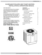
LOCATING THE POOL HEATER FOR INSTALLATION
The AQUEFIER Pool Heater must be installed outside near the pool pump/filter on a level area.
Special care must be taken to ensure that air flow is not restricted on the side air inlets, the heat
pump coil, or the top air discharge. Allow at least 12 inches clearance on all sides and 4 feet
clearance on top of the Pool Heater. Good Practice suggests allowing at least 4 feet of clearance on
the front of the Pool Heater for service access.
The unit should be set on a solid, level foundation, preferably a concrete slab at least 4 inches thick.
The slab should be above ground level and surrounded by a graveled area good for drainage since
water will condense on the outside of the unit during normal operation. The slab used as a unit
foundation should not adjoin the building, as it is possible that sound and vibration may be
transmitted to the structure.
Other location considerations include:
1. Keep the Pool Heater at least 10 to 15 feet away from pool chemical storage to minimize effects
of corrosive chemical vapors, particularly chlorine vapors.
2. Allow for proper drainage of condensation formed by the normal operation of the heat pump.
3. Do not install the Pool Heater in an enclosed area, such as a filter equipment room. It is
important to prevent the cool discharge air from being drawn back into the heat pump.
A beach location presents additional concerns. Exposure to salt water spray and high winds will
cause premature wear on the heat pump. Salt and sand accumulation will clog up the heat pump coil,
causing both corrosion and severely reduced efficiency. Preventive measures include: building a
windbreak around the heat pump; raise the pool heater up off the beach to reduce sand being sucked
in; increased frequency of cleaning of the fan motor and heat pump coil.
Finally, special care must be taken to check the elevation of the Pool Heater relative to the pool
water level. The AQUEFIER Pool Heater uses a pressure switch to determine that water flow is
present. If the Pool Heater is located more than 3 feet below the pool water level, or if the pool
piping passes more than 3 feet above the water inlet of the Pool Heater, the Pool Heater’s pressure
switch can be fooled into a false reading. This will result in the Pool Heater starting up without
water flow, and potentially damaging the Heater. Furthermore, an excessively dirty filter can reduce
the water flow enough to prevent the pressure switch from turning the Pool Heater on.

INSTALLING THE POOL HEATER
Pool Heater installation is divided into two sections: electrical connections, and pool piping
connections. The Factory has fully installed the refrigeration loop and preset the controls. There are
no job-site installation requirements for the heat pump. Wiring should only be done by licensed
electricians.
ELECTRICAL CONNECTIONS
Power to the Pool Heater
The AQUEFIER Pool Heater requires a separate 230 volt, 50 amp. circuit with a breaker, and a
ground connection. The pool heater grounding conductor shall be the same size or larger than the
live power supply conductors.
Use a length of watertight flexible conduit to connect to the Pool Heater cabinet. Enter the Pool
Heater cabinet through the openings provided at the rear corner of the cabinet. Connect to the pigtail
provided inside the cabinet or wire direct to the heat pump control box. Ground the heat pump per
local codes.
This pool heater is to be installed in accordance with Article 680 of the National Electrical Code,
ANSI/NFPA 70, and with the requirements of the authority having jurisdiction.
For more detailed instructions on installing the power refer to the Goodman Heat Pump instructions
enclosed.
Bonding to Pool Steel: Electrical corrosion, known as electrolysis, will occur if the heater is not
bonded to the pool reinforcement steel. Most local codes also require that the water pump be
bonded. Connect using a #8 gauge or larger solid copper wire to bond the cabinet to the pool
reinforcement steel.
Power to the Pool Pump
A standard feature on the Aquifier Pool Heater is the Pump Hold Relay. Since the pool heater can
not run without water flow, the Pump Hold Relay will keep the pool pump and the pool heater
running until the pool has reached the desired temperature setpoint. If the pump hold relay is not
wired in, the heater can only run when the pump is either turned on manually, or by the pump timer.
To wire this important feature in, the pool heater requires a circuit from the pool pump timer to the
pool heater, and a circuit from the pool heater to the pool pump. See Figure 1, Pool Pump to Hold
Relay Wiring Schematic. The Pump Hold Relay can be used with either a 120 volt or a 230 volt, 1
phase pump, with current draws up to 25 amps. It should be noted that power to the pump can be
supplied by the Timer and the Pump Hold Relay at the same time. The polarity of both sources of
power to the pump must be the same. See Figure 1. The power supply to the timer and the pump
hold relay must come from the same breaker.

1. Wiring must be sized per National Electrical Code requirements based on the pump load and
conductor length.
2. Conductors must be installed in approved conduit.
3. The pool heater, the pool pump, and the pump timer must be grounded per National Electrical
Code requirements.
Open the pool timer and connect a second set of wires to the line side terminals. Use a length of
watertight flexible conduit to connect to the Pool Heater cabinet, entering through the openings
provided on the rear side of the cabinet. Remove the front panel from the pool heater. Connect to the
black wires labeled #1 and #2 hanging from the Pool Heater’s control box.
Open the junction box on the pool pump and connect a second set of wires to the pump terminals.
Use a length of watertight flexible conduit to connect to the Pool Heater cabinet, entering through
the openings provided on the rear of the cabinet. Connect to the pair of blue wires, labeled #1 and
#2, found hanging from the Pool Heater’s control box. Be sure that the polarity is correct.
Replace the front panel on the cabinet.
POOL PIPING CONNECTIONS
The Pool Heater is designed to handle the full flow from the pool pump. No bypass is required if the
water flow is in the 20 to 80 gallon per minute range.
The Pool Heater piping must be connected at a point in the pool piping loop after the pool water
passes through the filter and before the chlorinator or chemical feeder. Connecting the Pool Heater
after the chlorinator will cause premature failure of the Pool Heater. Failure due to chemical
damage is not covered under the Factory Warranty. To prevent back-siphoning of the chlorinator
when the pool pump is turned off, install a chemically resistant check valve and a piping loop that
extends at least 8 inches above the top of the chlorinator.
The Pool Heater comes equipped with clear PVC stubs to allow a visual check of water flow and
water condition. Connect to these stubs with 2 inch PVC couplings and an appropriate length of 2
inch PVC pipe; taking care to note which stub is “water in” and which is “water out”. Good practice
also suggests considering the use of 3 way valves on the inlet and outlet to enable the pool owner to
bypass the Pool Heater if service or maintenance is required.

OPERATING THE POOL HEATER
The AQUEFIER Pool Heater is designed to be easy to operate. The front panel contains an on/off
switch and a digital temperature control readout. With the on/off switch turned to the “on” position,
the Pool Heater is set to reach and then maintain the selected pool water temperature, as long as the
pool pump is running. Once the selected pool temperature has been reached, control of the pool
pump is returned to the pool timer. The Pool Heater will keep the pool pump running if the timer
shuts off before the selected temperature is reached.
NOTE: The Pool Heater will not run without water flow.
Water Temperature Control
The digital temperature control is Factory set to 85F. Depending on the AQUEFIER Pool Heater
Model purchased, it may be equipped with a Control Panel Temperature Adjustment Knob or it may
be equipped with a manual control without external temperature control. To select a different
temperature, either simply adjust the knob clockwise or counter-clockwise; or remove the clear
plastic weather cover, insert the 1/8 th inch hex wrench (provided) through the opening in the face of
the digital temperature control, and adjust the set point up or down as desired.
For more detailed instructions on the digital temperature refer to the Goldline SP-33 instructions
enclosed.
After adjusting the temperature control, check the water temperature with an accurate thermometer.
CAUTION: Prolonged immersion in hot water may induce hyperthermia.
Hyperthermia occurs when the internal temperature of the body reaches several degrees above the
normal body temperature of 98.6 degrees F. The symptoms of hyperthermia include dizziness,
fainting, drowsiness, lethargy, and an increase in the internal temperature of the body. The effects of
hyperthermia include:
Unawareness of impending hazard;
Failure to perceive heat;
Failure to recognize the need to exit the pool or tub;
Physical inability to exit the pool or tub;
Fetal damage in pregnant women; and
Unconsciousness resulting in danger of drowning.
WARNING: The use of alcohol, drugs, or medication can greatly increase the risk of fatal
hyperthermia in pools and tubs.

Sequence of Operation
The control system includes a time delay to accurately check the pool water temperature, and
an anti-cycle timer to protect the compressor.
The time delay allows the control to get an accurate reading of the pool water temperature.
The water in the heater may be hotter or colder than the water in the pool depending on weather
conditions. To measure pool water temperature accurately, the time delay allows the pool pump to
run for 4 minutes before it measures temperature.
If there is a call for heat, the control will check to see if the compressor has been running during the
last 4 minutes. If the heater has been off for more than 4 minutes, the heater will start immediately.
If the heater has been either on during the last 4 minutes, or if power has been interrupted during the
last 4 minutes, the heater will not be allowed to start for an additional 4 minutes.
In most cases, the heater will not start until at least 8 minutes has passed without
resetting the on/off switch or the breakers.
The heater will continue to heat the pool until the temperature setpoint has been satisfied.
PLEASE NOTE:
1. It is important to remember that the pool heater will not run unless the pool pump is running.
2. Water vapor will condense on the outside of the unit and drain during normal operation.
3. There is up to an 8 minute start delay built into the controls to prevent the compressor short
cycling, and to assure that the temperature control is reading the pool water temperature
accurately.
4. Raising the temperature control set point above the pool water temperature will not cause the
heat pump to start up until the delay has been satisfied.
5. The digital temperature control will read the current pool water temperature whenever there is
power to the heat pump. The temperature reading is not necessarily accurate unless the pool
pump is moving water through the Pool Heater.


Pool Heater Operating Conditions:
Water Side Pressure Drop
Water Flow
(gal./min.) Pressure
Drop
(psig)
20 0.23
30 0.46
40 0.74
50 1.06
60 1.42
70 1.86
80 2.32
Temperature Rise Across Heater
Water Flow
(gal./min.) Temperature
Rise
(deg. F)
20 10.0
30 6.7
40 5.0
50 4.0
60 3.3
70 2.8
80 2.5

Startup Troubleshooting
PROBLEM
POSSIBLE CAUSE SOLUTION
Temperature display not lit
Unit will not start Check power supply to unit.
Check circuit breaker or fuses
Check 24 volt transformer
Turn on or reset breaker.
Check transformer/replace if
required.
Temperature display lit
Unit will not start. Switch to “on” position.
Water flow less than the 20
gpm minimum required.
Time delay and anticycle
timers satisfied.
Temperature set to low.
Check on/off switch.
Check that pump is on.
Check that water is flowing
through heater.
Check any bypass valves that
are installed.
Check filtering system.
Check pump and impeller.
Check that pressure switch is
closed. (needs 2 psi to close)
Wait at least 8 min. without
resetting on/ off switch or
breakers.
Set temperature setpoint above
water temperature.
Goldline control terminals “C”
and “NO” close on call for
heat.
Pool water does not reach
temperature setpoint. Heater runs only when pool
timer is on.
Outside air temperature is low.
Pool pump hold relay not
wired in at installation.
Electrician needs to wire pool
pump hold relay per Figure 1.
Install blanket on pool.
Water dripping from bottom
of unit. Water vapor will condense on
the outside of the evaporator
coil during normal operation.
Leak at pipe connection
No action. This is normal.
Repair as required.

POOL HEATER WCC100B, WCC100C, WCC100L
LIMITED WARRANTY
FOR RESIDENTIAL APPLICATIONS
(5 year parts/ 1 year labor)
Trevor-Martin Corporation warrants each Pool Heater to be free of defects in materials and
workmanship for 12 months from the Date of Installation. In the absence of suitable proof of
Date of Installation (Bill of sale), the Warranty Period will commence 30 days after the Date of
Manufacture. Additional warranty coverage applies to specific components as follows: Heat
Pump components have a five year Limited Warranty offered by their manufacturer, Goodman
Manufacturing Company; Trevor-Martin Corporation manufactured and/or supplied components
have a five year parts Limited Warranty. Failures resulting from improper installation, abuse,
accident, negligence, freezing, hard water, scale buildup, chemicals, external leakage, or Acts of
God are specifically excluded from Warranty Coverage.
This constitutes the only Warranty in connection with this sale; and is in lieu of all other
Warranties, expressed or implied, written or oral. No employee, agent, dealer or other person is
authorized to give any other Warranty on behalf of Trevor-Martin Corporation; nor to assume for
Trevor-Martin Corporation any other liability in connection with this product; except as may be
authorized by an officer of Trevor-Martin Corporation in a signed written document.
THERE ARE NO IMPLIED WARRANTIES OF MERCHANTABILITY OR FITNESS FOR A
PARTICULAR PURPOSE THAT APPLY TO THIS SALE.
LIMITATION OF REMEDY
Trevor-Martin Corporation will replace or repair, at its option, any product or component found
to be defective during the Warranty Period: either by act of Factory Service on the installed
product; or if such product or component is returned to our Factory, listed below, freight prepaid.
All such returns of product require Factory authorization prior to shipment. Trevor-Martin
Corporation will not accept liability for unauthorized returns.
Replacement or repair is the exclusive remedy available from Trevor-Martin Corporation for any
product or component found to be defective. Trevor-Martin Corporation is not liable for labor
charges or damages of any sort whatsoever, including incidental or consequential damages,
associated with product or components returned under Warranty. For Warranty Service contact
the installing Contractor or Trevor-Martin Corporation @ 1-800-875-1490.
Products or components replaced or repaired under the terms of this Warranty will be returned,
transportation charges prepaid, by the best and most economical means.
Trevor-Martin Corporation
4151 112th Terrace North, Clearwater, FL 33762

/