Page is loading ...

06/11
*2P0611* Page 1
506750−01
*P506750-01*
RETAIN THESE INSTRUCTIONS
FOR FUTURE REFERENCE
E 2011 Lennox Industries Inc.
Dallas, Texas, USA
WARNING
Improper installation, adjustment, alteration, service or
maintenance can cause personal injury, loss of life, or
damage to property.
Installation and service must be performed by a licensed
professional installer (or equivalent) or a service agency.
WARNING
If this unit is to be installed in a mobile or manufactured
home application, the duct system must be sized to
achieve static pressures within the manufacturer’s
guidelines. All other installation guidelines must also be
followed. Failure to do so may result in equipment
damage, personal injury and improper unit performance.
WARNING
Electric shock hazard. Can cause injury
or death. Before attempting to perform
any service or maintenance, turn the
electrical power to unit OFF at disconnect
switch(es). Unit may have multiple power
supplies.
INSTALLATION
INSTRUCTIONS
13HPP UNITS
PACKAGED HEAT PUMP UNIT (2−5 TONS)
506750−01
06/11
Supersedes 03/11
TABLE OF CONTENTS
Shipping and Packing List 1. . . . . . . . . . . . . . . . . . . . .
Unit Dimensions − inches (mm) 2. . . . . . . . . . . . . . . . .
Parts Arrangement 3. . . . . . . . . . . . . . . . . . . . . . . . . . . .
General 3. . . . . . . . . . . . . . . . . . . . . . . . . . . . . . . . . . . . .
Use of Unit as a Construction Heater or
Air Conditioner 3. . . . . . . . . . . . . . . . . . . . . . . . . . . . .
Requirements 4. . . . . . . . . . . . . . . . . . . . . . . . . . . . . . . .
Location Selection 4. . . . . . . . . . . . . . . . . . . . . . . . . . . .
Rigging and Setting Unit 4. . . . . . . . . . . . . . . . . . . . . . .
Clearances 5. . . . . . . . . . . . . . . . . . . . . . . . . . . . . . . . . .
Electrical 5. . . . . . . . . . . . . . . . . . . . . . . . . . . . . . . . . . . .
Optional Electric Heat 6. . . . . . . . . . . . . . . . . . . . . . . . .
Existing Common Vent Systems 6. . . . . . . . . . . . . . . .
Thermostat 6. . . . . . . . . . . . . . . . . . . . . . . . . . . . . . . . . .
Condensate Drain 8. . . . . . . . . . . . . . . . . . . . . . . . . . . .
Air Filters 8. . . . . . . . . . . . . . . . . . . . . . . . . . . . . . . . . . . .
Supply and Return Duct Connections 8. . . . . . . . . . .
Compressors 8. . . . . . . . . . . . . . . . . . . . . . . . . . . . . . . . .
Blower Speed Settings and Performance Data 9. . . .
Start−Up 12. . . . . . . . . . . . . . . . . . . . . . . . . . . . . . . . . . . . .
System Operation 13. . . . . . . . . . . . . . . . . . . . . . . . . . . .
Defrost System 12. . . . . . . . . . . . . . . . . . . . . . . . . . . . . . .
System Performance 14. . . . . . . . . . . . . . . . . . . . . . . . . .
Maintenance 15. . . . . . . . . . . . . . . . . . . . . . . . . . . . . . . . .
Planned Service 15. . . . . . . . . . . . . . . . . . . . . . . . . . . . . .
Shipping and Packing List
1 − Assembled packaged heat pump unit
As soon as the unit is received, it should be inspected for
possible damage during transit. If you find any damage,
immediately contact the last carrier.
CAUTION
Danger of sharp metallic edges. Can cause injury. Take
care when servicing unit to avoid accidental contact with
sharp edges.
Litho U.S.A.

Page 2
Unit Dimensions − inches (mm)
BACK VIEW
TOP VIEW
RIGHT SIDE
LEFT SIDE
Coil Access
Panel Condensate Drain
3/4 NPT
Return
Supply
Supply
Return
A
B
C
D
E
F
F
G
J
L
K
FF
G
4 (102)
1−5/8 (16)
5−1/2
(140)
H
Power Supply
1−1/8 (29)
Low Voltage Entry
7/8 (22)
Blower
Access
Panel
Riggig Hole (8)
M
P
N
2 (51)
Electric Heat
Power Entry
Model No. A B C D E F G
in mm in mm in mm in mm in mm in mm in mm
13HPP24A
13HPP30A
13HPP36A
32−1/2 826 46−1/2 1181 46−1/2 1181 45−5/8 1159 45−5/8 1159 17−1/2 445 11−1/2 292
13HPP42A
13HPP48A
13HPP60A
34−1/2 876 55−1/2 1410 50−1/2 1283 54−5/8 1387 49−5/8 1260 21−1/2 546 12 305
Model No. H J K L M N P
in mm in mm in mm in mm in mm in mm in mm
13HPP24A
13HPP30A
13HPP36A
4 102 4 102 1−3/4 44 15−5/8 397 27−3/4 705 24−7/8 857 9−3/4 248
13HPP42A
13HPP48A
13HPP60A
6−1/4 159 5−5/8 143 2−3/8 60 17−1/8 435 29−3/4 756 26−7/8 661 15−1/2 394

Page 3
Parts Arrangement
OUTDOOR FAN
OUTDOOR
COIL
COMPRESSOR
DEFROST CONTROL
HEATER COVER (FOR
OPTIONAL ELECTRIC HEAT)
CAPACITOR
CONTACTOR
BLOWER MOTOR
BLOWER
TRANSFORMER
ELECTRIC HEAT SECTION
(ORDERED SEPARATELY)
GRILLE
INDOOR COIL
Figure 1. Parts Arrangement
General
These installation instructions are intended as a general
guide only, for use by an licensed professional installing
contractor (or equivalent).
The 13HPP units are single−package heat pump units
designed for outdoor installation on a rooftop or a slab.
Electric heat sections are available for separate order.
The unit must be sized based on heat loss and heat gain
calculations made according to the methods of the Air
Conditioning Contractors of America (ACCA).
The units are shipped assembled. All piping, refrigerant
charge and electrical wiring are factory−installed and
tested. The units require electric power, condensate drain
and duct connections at the point of installation.
Use of Unit as a Construction Heater or
Air Conditioner
Use of this unit as a construction heater or air conditioner
is not recommended during any phase of construction.
Very low return air temperatures, harmful vapors and
operation of the unit with clogged or misplaced filters will
damage the unit.
If this unit has been used for heating or cooling of buildings
or structures under construction, the following conditions
must be met or the warranty will be void:
SA room thermostat must control the unit. The use of
fixed jumpers that will provide continuous heating or
cooling is not allowed.
SA pre−filter must be installed at the entry to the return
air duct.
SThe return air duct must be provided and sealed to the
unit.
SReturn air temperature range between 55°F (13°C)
and 80°F (27°C) must be maintained.
SAir filters must be replaced and pre−filter must be
removed upon construction completion.
SThe unit components, duct system, air filters and
evaporator coil must be thoroughly cleaned following
final construction clean−up.

Page 4
SThe unit operating conditions (including airflow,
cooling operation and heating operation) must be
verified according to these installation instructions.
Requirements
These units must be installed in accordance with all
applicable national and local safety codes.
These instructions are intended as a general guide and do
not supersede local codes in any way. Consult authorities
having jurisdiction before installation.
If components are to be added to a unit to meet local codes,
they are to be installed at the dealer’s and/or customer’s
expense.
These units are design−listed by ETL in both the United
States and Canada as follows:
SFor use as a heat pump unit.
SFor outdoor installation only.
SFor installation on combustible material.
WARNING
Product contains fiberglass wool.
Disturbing the insulation in this product during installa-
tion, maintenance, or repair will expose you to fiberglass
wool dust. Breathing this may cause lung cancer. (Fiber-
glass wool is known to the State of California to cause
cancer.)
Fiberglass wool may also cause respiratory, skin, and
eye irritation.
To reduce exposure to this substance or for further infor-
mation, consult material safety data sheets available
from address shown below, or contact your supervisor.
Lennox Industries Inc.
P.O. Box 799900
Dallas, TX 75379−9900
Location Selection
Use the following guidelines to select a suitable location for
these units.
1. Unit is designed for outdoor installation only. Unit must
be installed so all electrical components are protected
from water.
2. Condenser coils must have an unlimited supply of air.
3. For ground level installation, use a level pre−fabricated
pad or use a level concrete slab with a minimum
thickness of 3 inches. The length and width should be
at least 6 inches greater than the unit base. Do not tie
the slab to the building foundation.
4. Maintain level within a tolerance of 1/4 inch (6.35mm)
maximum across the entire length or width of the unit.
The heat pump unit foundation should be raised to a
minimum of 3 inches (75mm) above finish grade. In areas
which have prolonged periods of temperature below
freezing and snowfall, the heat pump unit should be
elevated above the average snow line. Extra precaution
should be taken to allow free drainage of condensate from
defrost cycles to prevent ice accumulation. The unit should
not be located near walkways to prevent possible icing of
surface from defrost condensate.
Rigging and Setting Unit
Exercise care when moving the unit. Do not remove any
packaging until the unit is near the place of installation.
Spreaders whose length exceeds the largest dimension
across the unit MUST be used across the top of the unit.
Units may also be moved or lifted with a forklift while still in
the factory−supplied packaging.
NOTE Length of forks must be a minimum of 42 inches
(1067mm).
This unit is shipped with four corner brackets in place on the
underside of the unit (see figure 2). The two rear corner
brackets must be removed before unit is installed on a
field−provided roof curb assembly, provided curb is a split
level design.
NOTE Heat pumps are designed to drain water during
the defrost cycle through holes in the base that are located
under the outdoor coil. In downflow applications, proper
clearances and/or drainage collection/management may
be required at installation to ensure water does not enter
structure.
Return Supply
REAR
CORNER
BRACKET
REAR
CORNER
BRACKET
REMOVE REAR CORNER BRACKETS BEFORE INSTALLING ON ROOF
CURB. LEAVE FRONT CORNER BRACKETS ON UNIT FOR SUPPORT.
FRONT
CORNER
BRACKETS
FRONT
CORNER
BRACKET
Figure 2. Corner Brackets
CAUTION
Before lifting a unit, make sure that the weight is
distributed equally on the cables so that it will lift evenly.
Units may also be moved or lifted with a forklift while still in
the factory−supplied packaging.

Page 5
Clearances
All units require certain clearances for proper operation
and service. Refer to figure 3 for the clearances required
for combustible construction, servicing, and proper unit
operation.
NOTE TOP CLEARANCE UNOBSTRUCTED MINIMUM 48" (1219)
24 (610)
24
(610)
24 (610)
0 (0)
Figure 3. Clearances Inches (MM)
Electrical
All wiring should be done in accordance with the
current National Electric Code ANSI/NFPA No. 70 in the
United States. In Canada, wiring must be done in
accordance with the current CSA C22.2 Part 1. Local
codes may take precedence.
Use wiring with a temperature limitation of 75_C minimum.
Run the 208 or 230 volt, 60 hertz electric power supply
through a disconnect switch to unit control box and connect
as shown in the wiring diagram located on the inside of the
control access panel. Electric power supply must be
properly protected with either a fuse or circuit breaker, see
unit nameplate.
Unit must be grounded with a separate ground conductor.
See figure 4 for typical field wiring connection. The wiring
diagram can be found on the unit inside the access panel.
Low voltage control wiring are pigtail leads located on the
main control box and are color−coded to match the
connection called out on the wiring schematic.
Power supply to the unit must comply with all applicable
codes and NEC or CEC. A fused disconnect switch should
be field provided for the unit. The switch must be separate
from all other circuits. If any of the wire supplied with the
unit must be replaced, replacement wire must be of the
type shown on the wiring diagram.
Electrical wiring must be sized to carry minimum circuit
ampacity marked on the unit. USE COPPER
CONDUCTORS ONLY. Each unit must be wired with a
separate branch circuit and be properly protected with a
fuse or circuit breaker, see unit nameplate.
WARNING
Unit is equipped with a single−pole contactor. Line
voltage is present at all components when unit is not in
operation. Disconnect all remote electric power supplies
before opening access panel. Unit may have multiple
power supplies. Failure to disconnect all power supplies
could result in personal injury or death.
CAUTION
When connecting electrical power and control wiring to
the unit, waterproof type connectors MUST be used so
that water or moisture cannot be drawn into the unit dur-
ing normal operation.
WARNING
Unit must be grounded in accordance with national and
local codes. Failure to ground unit properly can result in
personal injury or death.
See figure 4 for typical field wiring connections and figure 5
for typical unit wiring diagram.
If the optional electric heat section is installed, the electric
heat section requires a separate electrical power supply
with a disconnect and is properly protected with either a
fuse or circuit breaker.
IF 208 VOLT IS SUPPLIED, TRANSFORMER CONNECTIONS MUST BE CHANGED.
CONTACTOR
GROUND LUG
FIELD−SUPPLIED FUSED
OR CIRCUIT BREAKER
DISCONNECT
SINGLE−PHASE
POWER SUPPLY
Figure 4. 208/230 Line Voltage Wiring

Page 6
Optional Electric Heat
Optional electric heat is available and must be purchased
separately. Install the electric heat section as outlined in
the electric heat installation instruction included with heat
section.
Follow the basic steps listed below to install the electric
heat section. Refer to the electric heat installation
instruction for specific wiring/ heater configuration.
1. Disconnect the power and open the main control
access.
2. Disconnect the plug separating the high voltage wire
harness. Remove the high voltage wire harness plug
and discard.
3. Remove the heater block cover by removing the four
screws holding it in place. Cut away the insulation
covering the opening, using the hole in the panel as a
template.
4. Insert the heater into the control panel and fasten in the
same mounting holes.
5. Plug the heater wiring harness into the wire harness on
the control assembly. Field wiring of the auxiliary
heater is separate from the unit power supply. Wire the
power supply wiring for the heater to the appropriate
connections on the heater kit.
Table 1. Electric Heat Kits (208/240V−1ph)
Heater Model Lennox Catalog Number
5 kW 40K65
7 kW 40K66
10 kW 40K67
15 kW 40K68
20 kW 40K69
Existing Common Vent Systems
The 13HPP packaged heat pump may be used to replace
an existing gas furnace which is being removed from a
venting system commonly run with separate gas
appliances. In this case, the existing vent system is likely
to be too large to properly vent the remaining attached
appliances.
Conduct the following test while each appliance is
operating and the other appliances (which are not
operating) remain connected to the common venting
system. If the venting system has been installed
improperly, you must correct the system.
1. Seal any unused openings in the common venting
system.
2. Inspect the venting system for proper size and horizontal
pitch. Determine that there is no blockage, restriction,
leakage, corrosion, or other deficiencies which could
cause an unsafe condition.
3. Close all building doors and windows and all doors
between the space in which the appliances remaining
connected to the common venting system are located
and other spaces of the building. Turn on clothes
dryers and any appliances not connected to the
common venting system. Turn on any exhaust fans,
such as range hoods and bathroom exhausts, so they
will operate at maximum speed. Do not operate a
summer exhaust fan. Close fireplace dampers.
4. Follow the lighting instructions. Turn on the appliance
that is being inspected. Adjust the thermostat so that
the appliance operates continuously.
5. After the main burner has operated for five minutes,
test for leaks of flue gases at the draft hood relief
opening. Use the flame of a match or candle.
6. After determining that each appliance connected to the
common venting system is venting properly, (step 3)
return all doors, widows, exhaust fans, fireplace
dampers, and any other gas−burning appliances to
their previous mode of operation.
7. If a venting problem is found during any of the
preceding tests, the common venting system must be
modified to correct the problem.
Resize the common venting system to the minimum
vent pipe size determined by using the appropriate
tables in Appendix G. (These are in the current
standards of the National Fuel Gas Code
ANSI-Z223.1/NFPA 54 in the USA, and the
appropriate Category 1 Natural Gas and Propane
appliances venting sizing tables in the current
standards of the CSA B149 Natural Gas and Propane
Installation Codes in Canada.)
Thermostat
The room thermostat should be located on an inside wall
where it will not be subject to drafts, sun exposure or heat
from electrical fixtures or appliances. Follow
manufacturer’s instructions enclosed with thermostat for
general installation procedure. Color−coded insulated
wires (# 18 AWG) should be used to connect thermostat to
unit.

Page 7

Page 8
Figure 5. Wiring Diagram − Single Phase
Condensate Drain
The 13HPP unit is equipped with a 3/4 inch FPT coupling
for condensate line connection. Plumbing must conform to
local codes. Use a sealing compound on male pipe
threads.
UNIT
MINIMUM PITCH
1 IN. (25 MM) PER 10’
(3 M) OF LINE
MOUNTING
FRAME
OPEN
VENT
TRAP MUST BE DEEP ENOUGH TO OFFSET
MAXIMUM STATIC DIFFERENCE (GENERALLY, 3
INCHES MINIMUM).
TYPICAL CONDENSATE DRAIN
Figure 6. Typical Condensate Drain
The drain line must be properly trapped and routed to a
suitable drain. See figure 6 for proper drain arrangement.
The drain line must pitch to an open drain or pump a
minimum of 1 inch (25.4mm) per 10 feet (3048mm) to
prevent clogging of the line. Seal around drain connection
with suitable material to prevent air leakage into return air
system.
NOTE Drain line connection may not carry the weight of
the unsupported drain line. Support the drain line, if
necessary.
NOTE Condensate must never drain on a rubberized
roof.
Drain piping should not be smaller than drain connection at
coil. An open vent in drain line will some times be required
due to line length, friction and static pressure. Drains
should be constructed in a manner to facilitate future
cleaning.
NOTE The condensate drain line MUST be trapped to
provide proper drainage.
CAUTION
Condensate line connection must be hand−tightened. Do
not use tools.
Air Filter
An air filter is not factory−supplied with the unit. A
field−provided air filter must always be in place during unit
operation. Air filter sizes are shown in table 2.
This unit is equipped with an internal air filter clip which is
located in the indoor coil compartment attached to the side
of the unit drain pan.
Table 2. Unit Air Filter Sizes inches (mm)
Unit Model Filter Size Filter
Quantity
−24, −30, −36 28 in. (711) X 24 in. (610) x 1 in. (26) 1
−42, −48, −60 30 in. (762) X 30 in (762). x 1 in. (26) 1
Supply and Return Duct Connections
The duct system should be designed and sized according
to the methods in Manual Q of the Air Conditioning
Contractors of America (ACCA).
A closed return duct system shall be used. This shall not
preclude use of economizers or outdoor fresh air intake. It
is recommended that supply and return duct connections
at the unit be made with flexible joints.
The supply and return air duct systems should be
designed for the CFM and static requirements of the job.
They should NOT be sized by simply matching the
dimensions of the duct connections on the unit.
Ducting installed outdoors MUST be insulated and
waterproofed.
CAUTION
When fastening duct system to side duct flanges on unit,
insert screws through duct flanges only. Do not insert
screws through casing. Outdoor duct must be insulated
and waterproofed.
Compressors
Units are shipped with the compressor mountings
factory−adjusted and ready for operation.
Unit compressors have internal protection. If there is an
abnormal rise in the compressor temperature, the
protector will open and the compressor will stop.
CAUTION
Do not loosen compressor mounting bolts.

Page 9
Blower Speed Settings and Performance
Data
Electric shock hazard. Can cause injury or
death. Before attempting to perform any
service or maintenance, turn the electrical
power to unit OFF at disconnect switch(es). Unit
may have multiple power supplies.
WARNING
!
Factory settings for the blower speed jumpers are given in
the wiring diagram in figure 5. Use the following tables to
determine the correct air volume for operation in heat and
cool mode.
Table 3. Motor Speed Tap Settings
Tap Purpose
Tap 1 Fan Only
Tap 2 Low Static Cooling
Tap 3 High Static Cooling
Tap 4 and 5 Used for electric heat. Refer to heater label for
proper selection.
Table 4. 13HPP24A Blower Performance (Horizontal Airflow1)
External Static
Pressure in. w.g.
Air Volume at Specific Blower Taps (cfm)
Tap 1
(Fan Only)
Tap 2
(Low Static Cooling)
Tap 3
(High Static Cooling)
2 Tap 4
(Electric Heat)
2 Tap 5
(Electric Heat)
0.20 640 830 950 900 1060
0.30 460 800 910 870 1030
0.40 370 760 880 830 980
0.50 − − − 710 840 800 960
0.60 − − − 640 800 730 930
0.70 − − − 600 750 690 910
0.80 − − − 570 700 640 860
NOTE All air data measured external to unit with dry coil and less filter.
1 For downflow air volume, add 0.10 in. w.g. to duct static.
2 Taps 4 and 5 are used with Optional Electric Heat. Refer to Electric Heat nameplate for proper heat tap selection
Table 5. 13HPP30A Blower Performance (Horizontal Airflow1)
External Static
Pressure in. w.g.
Air Volume at Specific Blower Taps (cfm)
Tap 1
(Fan Only)
Tap 2
(Low Static Cooling)
Tap 3
(High Static Cooling)
2 Tap 4
(Electric Heat)
2 Tap 5
(Electric Heat)
0.20 650 1030 1150 1110 1150
0.30 550 1000 1110 1070 1110
0.40 490 970 1080 1040 1080
0.50 430 930 1050 1000 1050
0.60 − − − 900 1010 970 1010
0.70 − − − 860 980 950 980
0.80 − − − 820 960 920 960
NOTE All air data measured external to unit with dry coil and less filter.
1 For downflow air volume, add 0.10 in. w.g. to duct static.
2 Taps 4 and 5 are used with Optional Electric Heat. Refer to Electric Heat nameplate for proper heat tap selection
Table 6. 13HPP36A Blower Performance (Horizontal Airflow1)
External Static
Pressure in. w.g.
Air Volume at Specific Blower Taps (cfm)
Tap 1
(Fan Only)
Tap 2
(Low Static Cooling)
Tap 3
(High Static Cooling)
2 Tap 4
(Electric Heat)
2 Tap 5
(Electric Heat)
0.20 650 1240 1320 1240 1320
0.30 590 1200 1260 1200 1260
0.40 500 1150 1230 1150 1230
0.50 430 1100 1200 1100 1200
0.60 − − − 1060 1160 1060 1160
0.70 − − − 1020 1120 1020 1120

Page 10
0.80 − − − 980 1080 980 1080
NOTE All air data measured external to unit with dry coil and less filter.
1 For downflow air volume, add 0.10 in. w.g. to duct static.
2 Taps 4 and 5 are used with Optional Electric Heat. Refer to Electric Heat nameplate for proper heat tap selection

Page 11
Table 7. 13HPP42A Blower Performance (Horizontal Airflow1)
External Static
Pressure in. w.g.
Air Volume at Specific Blower Taps (cfm)
Tap 1
(Fan Only)
Tap 2
(Low Static Cooling)
Tap 3
(High Static Cooling)
2 Tap 4
(Electric Heat)
2 Tap 5
(Electric Heat)
0.20 780 1450 1650 1510 1650
0.30 690 1370 1570 1430 1570
0.40 610 1280 1510 1380 1510
0.50 540 1200 1440 1290 1440
0.60 − − − 1120 1360 1220 1360
0.70 − − − 1060 1260 1150 1260
0.80 − − − 990 1160 1090 1160
NOTE All air data measured external to unit with dry coil and less filter.
1 For downflow air volume, add 0.10 in. w.g. to duct static.
2 Taps 4 and 5 are used with Optional Electric Heat. Refer to Electric Heat nameplate for proper heat tap selection
Table 8. 13HPP48A Blower Performance (Horizontal Airflow1)
External Static
Pressure in. w.g.
Air Volume at Specific Blower Taps (cfm)
Tap 1
(Fan Only)
Tap 2
(Low Static Cooling)
Tap 3
(High Static Cooling)
2 Tap 4
(Electric Heat)
2 Tap 5
(Electric Heat)
0.20 860 1650 1800 1650 1800
0.30 760 1600 1750 1600 1750
0.40 690 1550 1690 1550 1690
0.50 640 1500 1630 1500 1630
0.60 − − − 1440 1570 1440 1570
0.70 − − − 1370 1470 1370 1470
0.80 − − − 1290 1330 1290 1330
NOTE All air data measured external to unit with dry coil and less filter.
1 For downflow air volume, add 0.10 in. w.g. to duct static.
2 Taps 4 and 5 are used with Optional Electric Heat. Refer to Electric Heat nameplate for proper heat tap selection
Table 9. 13HPP60A Blower Performance (Horizontal Airflow1)
External Static
Pressure in. w.g.
Air Volume at Specific Blower Taps (cfm)
Tap 1
(Fan Only)
Tap 2
(Low Static Cooling)
Tap 3
(High Static Cooling)
2 Tap 4
(Electric Heat)
2 Tap 5
(Electric Heat)
0.20 1000 1820 1950 1820 1950
0.30 900 1790 1910 1790 1910
0.40 800 1730 1860 1730 1860
0.50 750 1670 1800 1670 1800
0.60 − − − 1630 1700 1630 1700
0.70 − − − 1530 1560 1530 1560
0.80 − − − 1380 1360 1380 1360
NOTE All air data measured external to unit with dry coil and less filter.
1 For downflow air volume, add 0.10 in. w.g. to duct static.
2 Taps 4 and 5 are used with Optional Electric Heat. Refer to Electric Heat nameplate for proper heat tap selection

Page 12
Start−Up
The cooling section is a complete factory package utilizing
an air−cooled condenser. The system is factory−charged
with HFC−410A refrigerant.
PRE−START CHECKLIST:
1. Make sure refrigerant lines do not rub against the
cabinet or each other.
2. Inspect all electrical wiring, both factory− and
field−installed, for loose connections.
3. Check voltage at the disconnect switch. Voltage must
be within the range listed on the unit nameplate. If not,
consult power company and have voltage condition
corrected before starting unit.
4. Recheck voltage with unit running. If power is not
within the range listed on the unit nameplate, stop the
unit and consult the power company. Check unit
amperage. Refer to unit nameplate for correct running
amps.
5. Make sure filter is in place before unit start−up.
COOLING SEQUENCE OF OPERATION
When the thermostat is in the cooling mode, the O circuit is
powered which energizes the reversing valve. Upon
cooling demand, the thermostat closes circuit R and Y to
close the unit contactor and start the compressor and
outdoor fan. The thermostat automatically closes R to G
circuit at the same time. This brings on the indoor blower at
the selected cooling fan speed. Upon satisfying cooling
demand, the thermostat will open the above circuits and
open the main contactor, stopping the compressor and
outdoor fan. If the unit is equipped with a delay timer, the
indoor blower will continue to operate for 90 seconds which
improves system efficiency.
HEATING SEQUENCE OF OPERATION
Upon heating demand, the thermostat closes circuit R to Y,
which closes the unit contactor, starting the compressor
and outdoor fan. The reversing valve is not energized in the
heating mode. The thermostat again automatically brings
on the indoor fan at the selected heating speed at the same
time. Upon satisfying heating demand, the thermostat
opens above circuits and stops unit operation.
System Operation
UNIT COMPONENTS
The outdoor unit and indoor blower cycle on demand from
the room thermostat. If the thermostat blower switch is in
the ON position, the indoor blower operates continuously in
the selected continuous blower speed.
Bi−Flow Liquid line Filter Drier
The unit is equipped with a large−capacity bi−flow filter drier
which keeps the system clean and dry. If replacement is
necessary, order another of the same design and capacity.
The replacement filter drier must be suitable for use with
HFC−410A refrigerant.
Low Pressure Switch
The 13HPP is equipped with an auto−reset low pressure
switch which is located on the vapor line. The switch shuts
off the compressor when the vapor pressure falls below the
factory setting. This switch, which is ignored during defrost
operation, closes at pressures at or above 30 + 5 psig (207
+ 34 kPa) and opens at 10 + 3 psig (69 + 21 kPa). It is not
adjustable.
High Pressure Switch
The 13HPP is equipped with an auto-reset high pressure
switch (single−pole, single−throw) which is located on the
liquid line. The switch shuts off the compressor when
discharge pressure rises above the factory setting. The
switch is normally closed and is permanently adjusted to
trip (open) at 590 + 15 psig (4068 + 103 kPa).
Defrost Thermostat
The defrost thermostat is located on the liquid line between
the check/expansion valve and the distributor. When
defrost thermostat senses 42°F (5.5°C) or cooler, the
thermostat contacts close and send a signal to the defrost
control to start the defrost timing. It also terminates defrost
when the liquid line warms up to 70°F (21°C).

Page 13
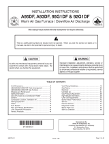
Defrost System
The defrost system includes a defrost thermostat (S6) and
a defrost control (CMC1).
DEFROST CONTROL
This defrost control includes the combined functions of a
time/temperature defrost control, defrost relay, time delay,
diagnostic LEDs, and a terminal strip for field wiring
connections.
24V TERMINAL
STRIP
CONNECTIONS
DIAGNOSTIC
LEDS
HIGH PRESSURE
SWITCH
TEST
PINS
DEFROST TIMING
PINS (P1)
REVERSING
VALVE
DEFROST
THERMOSTAT (S6)
LOW PRESSURE
SWITCH
COMPRESSOR
DELAY PINS
S4
S87
SERVICE LIGHT
CONNECTIONS
Figure 7. Defrost Control (CMC1)
The defrost control provides automatic switching from
normal heating operation to defrost mode and back. When
the defrost thermostat is closed, the control accumulates
compressor run time at 30, 60 or 90 minute field adjustable
intervals. When the selected compressor run time interval
is reached, the defrost relay is energized and defrost
begins.
Defrost Control Timing Pins (P1)
Each timing pin selection provides a different
accumulated compressor run time period for one defrost
cycle. This time period must occur before a defrost cycle
is initiated. The defrost interval can be adjusted to 30
(T1), 60 (T2), or 90 (T3) minutes (see figure 24). The
maximum defrost period is 14 minutes and cannot be
adjusted.
NOTE Defrost control part number is listed near the P1
timing pins.
SUnits with defrost control 100269−02: Factory default
is 60 minutes
SUnits with defrost control 100269−04: Factory default
is 90 minutes
If the timing selector jumper is missing, the defrost control
defaults to a 90−minute defrost interval.
Compressor Delay (P5)
The defrost control has a field−selectable function to
reduce occasional sounds that may occur while the unit is
cycling in and out of the defrost mode.
SUnits with defrost control 100269−02: The compressor
will be cycled off for 30 seconds going in and out of the
defrost mode when the compressor delay jumper is
removed.
SUnits with defrost control 100269−04: The compressor
will be cycled off for 30 seconds going in and out of the
defrost mode when the compressor delay jumper is
installed.
NOTE The 30−second compressor feature is ignored
when the jumper is installed on TEST pins.
Time Delay
The timed−off delay is five minutes long. The delay helps
protect the compressor from short−cycling in case the
power to the unit is interrupted or a pressure switch opens.
The delay is bypassed by placing the timer select jumper
across the TEST pins for 0.5 seconds.
NOTE The defrost control must have a thermostat
demand for the bypass function.
Test Mode (P1−TEST)
A TEST option is provided for troubleshooting. The TEST
mode may be started any time the unit is in the heating
mode and the defrost thermostat is closed or jumpered. If
the jumper is in the TEST position at power−up, the control
will ignore the test pins. When the jumper is placed across
the TEST pins for two seconds, the control will enter the
defrost mode. If the jumper is removed before an additional
5−second period has elapsed (7 seconds total), the unit will
remain in defrost mode until the defrost thermostat opens
or 14 minutes have passed. If the jumper is not removed
until after the additional 5−second period has elapsed, the
defrost will terminate and the test option will not function
again until the jumper is removed and re−applied.
Diagnostic LEDs (DS1 and DS2)
The defrost control uses two LEDs for diagnostics. The
LEDs flash a specific sequence according to the diagnosis
(table 10).
Table 10. Defrost Control Diagnostic LEDs
DS2 Green DS1 Red Condition
OFF OFF Power problem
Simultaneous Slow Flash Normal operation
Alternating Slow Flash 5−minute anti−short cycle delay
OFF Slow Flash Low Pressure Fault
OFF ON Low Pressure Lockout
Slow Flash OFF High Pressure Fault
ON OFF High Pressure Lockout

Page 14
System Performance
This equipment is a self contained, factory optimized using
check expansion valve metered refrigerant system, and
should require no adjustments when properly installed. If
however unit
Ensure unit is installed per manufacturer´s instructions and
that line voltage and air flows are correct. Refer to table 10
for proper superheat values. Check superheat settings by
measuring pressure at the suction line service port.
Measure pressure at the liquid service port. Take line
temperature within 2 inches of service port connection to its
main tube. If unit superheat subcooling varies by more than
table allowance, check internal seals, service panels and
duct work for air leaks, as well as restrictions and blower
speed settings. If unit performance remains questionable,
remove charge, evacuate to 500 microns, and weigh in
refrigerant to name plate charge. It is critical that the exact
charge is re−installed. Failure to comply will compromise
system performance. If unit performance is still
questionable, check for refrigerant related problems such
as, blocked coil or circuits, malfunctioning metering
devices or other system components.
Table 11. Suction Superheat Values
Unit Model No.
Suction Superheat +/− 3 DEG @
82_F OD / 80_F IDDB
/ 67_F IDWB
13HPP24 17_F
13HPP30 20_F
13HPP36 16_F
13HPP42 17_F
13HPP48 19_F
13HPP60 19_F
Verify system performance using table 12 as a general
guide. Table 12 should not be used for charging unit. Minor
variations in these pressures may be expected due to
differences in installations. Significant differences could
mean that the system is not properly charged or that a
problem exists with some component in the system.
Used carefully, this table could serve as a useful service
guide. Data is based on 80F dry bulb / 67F wet bulb return
air. Allow unit operation to stabilize before taking pressure
readings.
Table 12. Normal Operating Pressures (Cooling)
80F db / 67F wb RETURN AIR Air Temperature Entering Outdoor Coil (F)
UNIT PRESSURE 65 70 75 80 82 85 90 95 100 105 110 115
13HPP24
Vapor
133 136 138 141 142 143 146 148 150 152 154 156
13HPP30 133 136 139 142 143 144 146 150 151 152 154 156
13HPP36 134 138 142 145 147 148 151 154 156 157 158 158
13HPP42 128 133 137 142 144 145 147 149 151 152 154 155
13HPP48 126 130 133 137 138 139 142 145 147 148 149 150
13HPP60 127 130 133 136 137 138 140 143 144 145 147 149
13HPP24
Liquid
253 274 294 315 323 337 361 383 408 428 461 489
13HPP30 236 256 276 296 304 318 341 363 387 406 437 463
13HPP36 246 267 287 308 316 330 355 377 402 422 455 483
13HPP42 246 268 290 311 320 334 356 378 401 420 451 476
13HPP48 248 269 290 312 320 334 357 380 404 423 452 477
13HPP60 256 277 298 319 327 341 365 386 412 432 461 486
Table 13. Normal Operating Pressures (Heating)
70F RETURN AIR Air Temperature Entering Outdoor Coil (F)
UNIT PRESSURE 0 5 10 17 20 25 30 35 40 47 50 55 60
13HPP24
Vapor
38 45 52 61 65 72 78 85 92 101 105 112 118
13HPP30 36 43 51 61 66 73 81 88 96 106 111 118 126
13HPP36 38 46 54 65 70 78 85 93 101 112 117 125 132
13HPP42 38 45 53 63 67 75 82 89 97 107 111 119 126
13HPP48 37 44 51 61 65 72 79 86 93 103 107 114 121
13HPP60 35 42 48 58 62 69 76 83 89 99 103 110 117
13HPP24
Liquid
242 252 263 278 284 295 306 316 327 342 348 359 370
13HPP30 272 279 287 297 302 309 317 324 332 342 347 354 362
13HPP36 301 308 316 316 331 338 346 353 361 371 376 383 391
13HPP42 275 283 291 303 308 316 325 333 341 353 358 366 375
13HPP48 265 273 282 293 298 306 314 322 331 342 347 355 363
13HPP60 275 285 294 308 314 323 333 343 352 366 372 381 391

Page 15
Maintenance
At the start of each cooling season, this equipment should
be serviced by a licensed professional technician (or
equivalent). Periodic inspection and maintenance normally
consists of changing or cleaning filters.
CONDENSER FAN CLEARANCES
The hub of the condenser fan blade should be flush with the
end of the motor shaft to ensure proper clearances and
performance. This dimension should be checked and the
fan should be adjusted accordingly any time servicing of
the outdoor fan system is required.
AIR FILTER
Visually inspect vent outlet periodically to make sure that the
there is no buildup of soot and dirt. If necessary, clean to
maintain adequate opening to discharge flue products.
Motors
Indoor, outdoor fan and vent motors are permanently
lubricated and require no further lubrication. Motors
should be cleaned yearly to prevent the accumulation of
dust and dirt on the windings or motor exterior.
COIL
Dirt and debris should not be allowed to accumulate on the
coil surfaces or other parts in the air conditioning circuit.
Cleaning should be performed as often as necessary. Use
a brush, vacuum cleaner attachment, or other suitable
means. If water is used to clean the coil, be sure the power
to unit is shut off prior to cleaning.
NOTE Care should be used when cleaning the coil so
that the coil fins are not damaged.
Do not permit the hot condenser air discharge to be
obstructed by overhanging structures or shrubs.
Planned Service and (under some conditions)
cleaning the main burners
You should expect a service technician to check the
following items during an annual inspection. Power to the
unit must be shut off for the service technician’s safety.
SFresh air grilles and louvers Must be open and
unobstructed to provide air.
SUnit appearance must be inspected for:
ARust, dirt or signs of water
BBurnt or damage wires
CBurnt or damage components.
SA good coat of auto wax can enhance the appearance
of the cabinet.
SBlower access door must be properly in place.
SReturn air duct must be properly attached and must
provide an air seal to the unit.
SOperating performance Unit must be observed
during operation to monitor proper performance of the
unit and the vent system.
Problems detected during the inspection may make it
necessary to temporarily shut down the unit until the items
can be repaired or replaced.
Pay attention to your unit. Situations can arise between
annual unit inspections that may result in unsafe operation.
/