FA01133M4A - ver. 1 - 05/2018
General Precautions
Important people-safety instructions: READ CAREFULLY! • In-
stalling, programming, commissioning and maintenance must only
be done by qualified, expert sta and in full compliance with the
applicable law. • Wear antistatic protective clothing when working
on the control board. • Keep these precautions. • Always cut o the
mains power when doing cleaning and maintenance jobs. • This
product must only be used for its specifically intended purpose. Any
other use is dangerous. • The manufacturer declines all liability for
any damage as a result of improper, incorrect or unreasonable use.
Description
Wireless module with one relay-switch output, to command and
control an electric load and one 230 V AC digital input for control
devices.
This device is fitted with an external, hard-wired antenna whi-
ch must not be removed A.
Always keep the antenna wire taught and pointing upwards.
Do not install the device inside any boxes or metal cabinets.
Description and functions of the terminals, buttons and LEDs A
Terminals
NNeutral I1 Contact 1 input
LLine NO Relay contact (NO)
SERVICE button 2
On the CAME D SW software: for identifying the device during the
programming phase.
In manual configuration mode, it has the following functions:
1. ENTER/EXIT the learning phase
2. RESTORING the device's DEFAULT CONFIGURATION. Keep the but-
ton pressed for at least 30 seconds. The red LED will flash.
3. CONFIGURE THE RELAY-SWITCH OUTPUT
Yellow Service LED 3
It turns on every time the SERVICE button is pressed.
If it stays on or o, the module is either not working or is not powered
up.
TX red transmission LED 4
It turns on when a radio signal is transmitted; it flashes during the
learning phase.
RX green reception LED 5
It turns on when a radio signal is received.
Technical features
Range in wide open spaces (m)
Power-supply cable section (mm)2)
Maximum relative operating humidity without con-
densation (%)
<93
Operating temperature (°C)
Restrictions and checks
Maximum distance between a module and the control devices: 20 m.
If the input cables run next to the network conductors, the ma-
ximum distance is 10 m.
Make sure that the power supply network, in compliance with the
installation rules, is fitted with a two-wait cut o switch, that provides
category III protection levels;
Only install this device onto power panels fitted with a DIN
EN50022 guide, junction boxes or standard industry boxes.
Maximum controllable load of the relay-switch output (230 V
AC)
Type of load Max power
Resistive load (W) 1,250
Halogen lights (W) 1,000
Fluorescent lights, LEDs and compact fluorescent
lights (W) 250
Electronic transformers (W) 500
Motors (VA) 750
Ferromagnetic transformers (VA) 1,000
Configuration
Please refer to the CAME D SW manual for matching various module
via PC.
LEARNING
Use a screwdriver to press the SERVICE button for between 10 to 20
seconds; The red LED will flash.
MATCHING THE OH/1O05WL TO ANOTHER WIRELESS MODULE
Close the input on the device you are going to match to the module.
Keep the switch pressed for more than 3 seconds. B. The yellow
LED will stay on for 5 seconds.
MATCHING THE OH/1O05WL TO OTHER DEVICES
The following devices are also matchable:
- TH/500 WL and TH/550 chronothermostat (max 8) for piloting
zone electric-valves (these are matchable on the chronothermostat
menu) on heating and cooling systems.
- CAME radio perimeter-detector (for example, for switching lights
on and o) by pressing the learning button on the safety contact.
- CAME radio volumetric detectors (for example, for switching on
or enabling lights), by pressing the learning button on the sensor.
- CAME radio controls (for example for switching lights on and o)
by associating the radio control and the single buttons to match (see
CAME radio control instructions).
CONFIGURING THE RELAY-SWITCH OUTPUT
The relay-switch output is set to SWITCH by default.
On the the last matched input, to pass from one function to the next,
press the SERVICE button once.
When the button is pressed for the first time, the yellow LED will flash
as many times as the number of the associated function:
- One flash = Default switch-function: the output switches each
time the associated input's state is changed. NOTE. Function una-
vailable when a CAME radio control is associated.
- Two flashes = Step-by-step function: the output switches each
time the associated input is closed. This is a default function asso-
ciated to a radio control button.
- Three flashes = Impulsive function: the output will activate for 60
seconds (300 seconds for volumetric sensors) each time the asso-
ciated input is closed.
- Four flashes = ON function: the output activates each time the
associated input is closed. This default function is associated to the
opening of a magnetic contact).
- 5 flashes = OFF function: the output deactivates each time the
associated input is closed.
- One prolonged flash = it dissociates the input from the local input
(when the local input is selected).
By default, during manual configuration, the module's output swi-
tches each time the module's input changes state. To change the
input's function, during the learning phase, close the local input for
more than 10 seconds, and proceed as explained above (configuring
the relay-switch output). In this phase, the yellow LED turns on for
5 seconds.
EXITING THE LEARNING PHASE
Use a screwdriver to press the SERVICE button for between 10 to 20
seconds. The red LED will turn o.
Module's input functions
By default, during manual configuration, the module's output swi-
tches each time the module's input changes state. To change the
input's function, during the learning phase, close the local input for
10 seconds. Then proceed as explained in the 'Selecting relay fun-
ctions' paragraph. In this phase the yellow LED turns on.
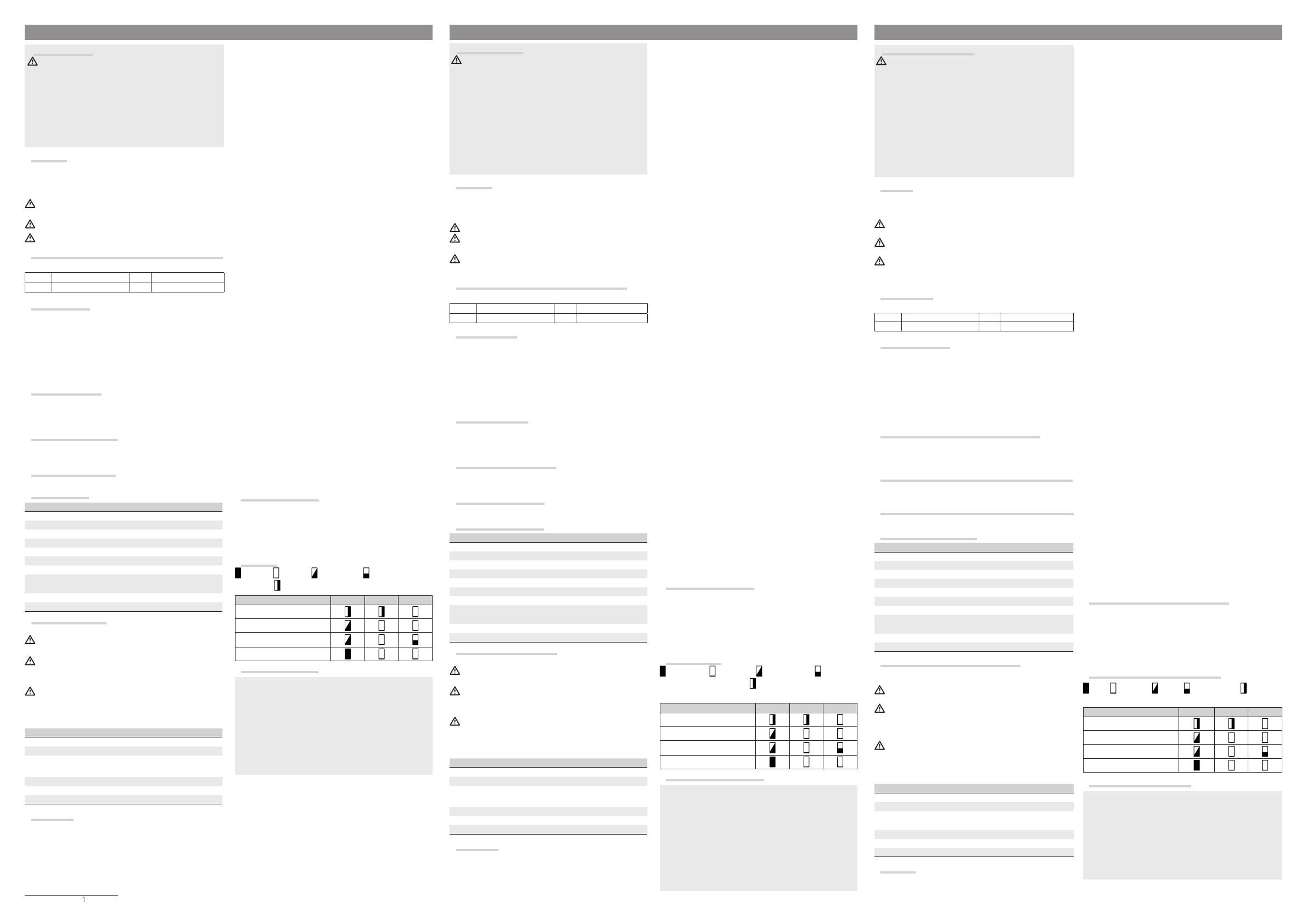
LED legend
LED is on, LED is o, LED is flashing LED flashed from one
to five times, LED flashes at each TX/RX signal
State of module red green yellow
Normal operation
Relay-switch learning
Change function
Default settings
Example of operation C
The manufacturer, CAME SpA, declares that the OH/1O05WL-type radio
equipment complies with directive 2014/53/EU.
You can find the complete wording of the EU declaration of conformity at:
http://www.came.com.
Decommissioning and disposal. Dispose of the packaging and the device
at the end of its life cycle responsibly, in compliance with the laws in force
in the country where the product is used. The recyclable components are
marked with a symbol and the material’s ID marker.
THE DATA PRESENTED IN THIS MANUAL MAY BE CHANGED, AT ANY TIME,
AND WITHOUT NOTICE.
MEASUREMENTS, UNLESS OTHERWISE STATED, ARE IN MILLIMETERS.
Общие правила безопасности
Важные правила техники безопасности: ПРОЧИТАЙТЕ ВНИМА-
ТЕЛЬНО! • Монтаж, программирование, ввод в эксплуатацию и тех-
ническое обслуживание должны производиться квалифицирован-
ным и опытным персоналом в полном соответствии с требованиями
действующих норм безопасности. • Используйте антистатическую
одежду и обувь при работе с электроникой. • Храните данные ин-
струкции. • Всегда отключайте электропитание перед выполнением
работ по чистке или техническому обслуживанию системы. • Это
изделие должно использоваться исключительно по назначению.
Любое другое применение рассматривается как опасное. • Фир-
ма-изготовитель снимает с себя всякую ответственность за ущерб,
нанесенный неправильным, ошибочным или небрежным использо-
ванием изделия.
Описание
Беспроводной модуль с 1 релейным выходом для управления
потребителем электроэнергии и 1 цифровым входом ~230 В для
устройств управления.
Устройство оборудовано внешней проводной антенной,
которую нельзя снимать 1.
Провод антенны должен быть все время натянут и направ-
лен вверх.
Не устанавливайте устройство внутри коробки или метал-
лического шкафа.
Описание и функции контактов, кнопок и светодиодных
индикаторов A
Контакты
NНейтраль I1 Входной контакт 1
LЛиния Н.О. Контакт реле (Н.О.)
Кнопка "SERVICE" B
Позволяет определить устройство на этапе программирования с
помощью программного обеспечения CAME D SW.
При настройке вручную с ее помощью можно:
1. ВХОДИТЬ/ВЫХОДИТЬ из режима определения.
2. ВОССТАНАВЛИВАТЬ НАСТРОЙКИ ПО УМОЛЧАНИЮ устройства.
Нажмите и удерживайте кнопку не менее 30 секунд, пока не за-
мигает (красный) светодиодный индикатор.
3. НАСТРОИТЬ РЕЛЕЙНЫЙ ВЫХОД
Светодиодный индикатор "Service" (желтый) C
Индикатор загорается всякий раз, когда нажимается кнопка
"SERVICE". Если он продолжает гореть или выключается, модуль
не работает или обесточен.
Светодиодный индикатор радиопередачи данных (красный) D
Он загорается при передаче радиосигнала и мигает на этапе
распознавания.
Светодиодный индикатор радиоприема данных (зеленый) E
Он загорается при получении радиосигнала.
Технические характеристики
Напряжение электропитания (~В)
Макс. потребляемый ток (мA)
Частота радиосигнала (МГц)
Мощность радиосигнала (дБм)
Дальность действия на открытой местности (м)
Сечение кабеля электропитания (мм2)
Макс. относительная влажность во время рабо-
ты (без образования конденсата) (%)
<93
Диапазон рабочих температур (°C)
Ограничения в использовании и проверки
Максимальное расстояние между модулем и устройствами
управления: 20 м.
Если входящие провода проложены с проводами сетевого
электропитания, максимальное расстояние составляет 10 м.
Для подключения к сети электропитания необходимо преду-
смотреть автоматический выключатель с расстоянием между
контактами не менее 3 мм, обеспечивающий защиту от пере-
напряжения III степени.
Устройство должно устанавливаться только в электрощите с
DIN-рейкой (EN50022), разветвительной коробке или монтажной
коробке для электроустановочных изделий.
Макс. нагрузка, управляемая релейным выходом (~230 В)
Тип нагрузки Макс. мощность
Активная нагрузка (Вт) 1250
Галогенные лампы (Вт) 1000
Флуоресцентные, светодиодные и флуорес-
центные компактные лампы (Вт) 250
Электронные трансформаторы (Вт) 500
Двигатели (ВА) 750
Ферромагнитные трансформаторы (ВA) 1000
Настройка
Руководствуйтесь инструкцией, прилагаемой к CAME D SW, для
присвоения различных модулей посредством ПК.
ОПРЕДЕЛЕНИЕ
С помощью отвертки нажмите и удерживайте 10-20 секунд
кнопку "SERVICE"; (красный) светодиодный индикатор мигает.
ПРИСВОЕНИЕ OH/1O05WL ДРУГОМУ БЕСПРОВОДНОМУ МОДУЛЮ
Замкните входные контакты устройства, присваиваемого модулю
(нажав и удерживая переключатель не менее 3 секунд) B. Жел-
тый светодиодный индикатор будет гореть в течение 5 секунд.
ПРИСВОЕНИЕ OH/1O05WL ДРУГИМ УСТРОЙСТВАМ
Возможно присвоение следующих устройств:
- Хронотермостат TH/500 WL и TH/550 (макс. 8) для управле-
ния зональными электромагнитными клапанами или насосами
(присвоение осуществляется с помощью меню хронотермостата)
систем отопления и охлаждения.
- Беспроводной периметральный извещатель CAME (на-
пример, для включения или выключения света) посредством
нажатия кнопки распознавания, предусмотренной на контакте
безопасности.
- Беспроводные объемные извещатели CAME (например, для
включения или выключения света) путем нажатия на кнопку рас-
познавания, предусмотренную на датчике.
- Пульты дистанционного управления CAME (например, для
включения или выключения света) посредством присвоения
пульта управления и последующего нажатия отдельных привя-
занных кнопок (см. инструкции к пульту дистанционного управ-
ления CAME).
НАСТРОЙКА РЕЛЕЙНОГО ВЫХОДА
По умолчанию релейный выход работает в режиме ВЫКЛЮЧАТЕЛЯ.
Для перехода из одного режима в другой на последнем присво-
енном входе нажмите кнопку "SERVICE" один раз.
При первом нажатии кнопки желтый светодиодный индикатор
вспыхнет то количество раз, которое соответствует выбранному
режиму:
- 1 вспышка - Режим переключателя (по умолчанию): выход
коммутирует при каждом изменении состояния присвоенного
входа. ПРИМЕЧАНИЕ. Функция недоступна при присвоении пуль-
та дистанционного управления CAME.
- 2 вспышки = Пошаговый режим: выход коммутирует при
каждом замыкании присвоенного входа (режим по умолчанию,
присвоенный кнопке пульта ДУ).
- 3 вспышки =Импульсный режим: выход активируется на 60
секунд (300 секунд для объемных извещателей) при каждом за-
мыкании присвоенного входа.
- 4 вспышки = Режим "ВКЛ.": выход активируется при каждом
замыкании присвоенного входа (режим по умолчанию, присво-
енный открытию магнитного контакта).
- 5 вспышек = Режим "ВЫКЛ.": выход деактивируется при ка-
ждом замыкании присвоенного входа.
- 1 длительная вспышка = Разделяет вход и локальный выход
(при выбранном локальном входе).
При ручной настройке выходные контакты модуля по умолчанию
переключаются при каждом изменении состояния входных кон-
тактов модуля. Для изменения режима входа на этапе распозна-
вания необходимо замкнуть локальный вход (>10 с) и выполнить
действия, описанные выше (в параграфе "Настройка релейного
выхода"). На этом этапе на 5 секунд загорается (желтый) свето-
диодный индикатор.
ВЫХОД ИЗ РЕЖИМА ОПРЕДЕЛЕНИЯ
С помощью отвертки нажмите и удерживайте кнопку "SERVICE"
10-20 секунд. Красный светодиодный индикатор погаснет.
Режим работы входных контактов модуля
При ручной настройке выходные контакты модуля по умолчанию
переключаются при каждом изменении состояния входных кон-
тактов модуля. Для изменения режима входа на этапе распозна-
вания необходимо замкнуть локальный вход (10 с) и выполнить
действия, описанные в параграфе "Выбор режима реле". На
этом этапе загорается светодиодный индикатор (желтый).
УСЛОВНЫЕ ОБОЗНАЧЕНИЯ ИНДИКАТОРА
Горит, выключен, мигает, мигает 1-5 раз, мигает при
каждом сигнале передатчика/приемника
Состояние модуля красный зеленый желтый
Нормальная работа
Распознавание реле
Изменение функции
Настройки по умолчанию
Пример функционирования C
Фирма-производитель CAME S.p.A. заявляет, что радиоаппаратура OH/1O05WL
соответствует требованиям Директивы 2014/53/UE.
Полный текст декларации о соответствии доступен по следующему адресу:
http://www.came.com.
Утилизация. Не выбрасывайте упаковку и устройство в окружающую среду.
Утилизируйте их в соответствии с требованиями законодательства, действую-
щего в стране установки. Компоненты, пригодные для повторного использова-
ния, отмечены специальным символом с обозначением материала.
СОДЕРЖАНИЕ ДАННОГО РУКОВОДСТВА МОЖЕТ БЫТЬ ИЗМЕНЕНО В ЛЮБОЕ
ВРЕМЯ БЕЗ ПРЕДВАРИТЕЛЬНОГО УВЕДОМЛЕНИЯ.
ВСЕ РАЗМЕРЫ ПРИВЕДЕНЫ В ММ, ЕСЛИ НЕ УКАЗАНО ИНОЕ.
Instructions générales
Instructions importantes pour la sécurité des personnes : À
LIRE ATTENTIVEMENT ! • L’installation, la programmation, la mise
en service et l'entretien doivent être eectués par du personnel
qualifié et dans le plein respect des normes en vigueur. • Porter
des vêtements et des chaussures antistatiques avant d'intervenir
sur la carte électronique. • Conserver ces instructions. • Toujours
couper le courant électrique durant les opérations de nettoyage
ou d'entretien. • Ce produit ne devra être destiné qu'à l'utilisation
pour laquelle il a été expressément conçu. Toute autre utilisation
est à considérer comme dangereuse. • Le fabricant décline toute
responsabilité en cas d'éventuels dommages provoqués par des
utilisations impropres, incorrectes et déraisonnables.
Description
Module sans fil avec une sortie à relais, pour commander et contrô-
ler une charge électrique, et une entrée numérique 230 VAC pour
dispositifs de commande.
Ne jamais enlever l’antenne filaire dont le dispositif est doté 1.
Le fil de l’antenne doit toujours être bien tendu et orienté
vers le haut.
Ne pas installer le dispositif dans des boîtiers ou une armoire
en métal.
Description et fonctions de bornes, boutons et leds A
Bornes
NNeutre I1 Entrée Contact 1
LLigne NON Contact relais (NO)
Bouton SERVICE 2
Par le logiciel CAME D SW : permet l'identification du dispositif en
phase de programmation. Ses fonctions en mode de configuration
manuelle sont les suivantes :
1. ENTRER/SORTIR de la phase d'apprentissage
2. RÉTABLIR LA CONFIGURATION PAR DÉFAUT du dispositif. Mainte-
nir le bouton enfoncé pendant au moins 30 s. La led (rouge) clignote.
3. CONFIGURER LA SORTIE RELAIS
LED Service (jaune) 3
Cette led s'allume à chaque enfoncement du bouton SERVICE. Si
elle reste allumée ou éteinte, le module ne fonctionne pas ou n'est
pas sous tension.
LED Transmission TX (rouge) 4
S'allume à la transmission d'un signal radio ; clignote en phase
d'apprentissage.
LED Réception RX (verte) 5
S'allume à la réception d'un signal radio.
Caractéristiques techniques
Puissance signal radio (dBm)
Portée en champ libre (m)
Section câble d'alimentation (mm²)
Humidité relative de fonctionnement maxi sans
condensation (%)
<93
Température de fonctionnement (°C)
Limites d'utilisation et contrôles
Distance maximale entre module et dispositifs de commande : 20 m.
Si les câbles des entrées passent à côté des conducteurs de
réseau, la distance maximale est de 10 m.
S’assurer que le réseau d’alimentation est bien doté, confor-
mément aux règles d’installation, d’un dispositif de déconnexion
omnipolaire pour la protection en cas de surtension catégorie III ;
Le dispositif ne doit être installé que dans une armoire électrique
dotée d'un rail DIN (EN50022), d'un boîtier de dérivation ou de boî-
tiers pour séries domestiques.
Charge maximale commandable par la sortie relais (230 VAC)
Type de charge Puissance max.
Charge résistive (W) 1250
Ampoules halogènes (W) 1000
Ampoules fluorescentes, led et fluorescentes
compactes (W) 250
Transformateurs électroniques (W) 500
Moteurs (VA) 750
Transformateurs ferromagnétiques (VA) 1000
Configuration
Se référer au manuel du logiciel CAME D SW pour la combinaison
des diérents modules par PC.
APPRENTISSAGE
Appuyer pendant 10-20 s sur le bouton SERVICE à l'aide d'un
tournevis ; la led (rouge) clignote.
ASSOCIATION D'UN MODULE OH/1O05WL À UN AUTRE MODULE
SANS FIL
Fermer l'entrée du dispositif à combiner au module (en appuyant
pendant plus de 3 s sur l'interrupteur) B. La LED (jaune) reste al-
lumée pendant 5 s.
ASSOCIATION D'UN MODULE OH/1O05WL À D'AUTRES DISPO-
SITIFS
Il est également possible de combiner les dispositifs suivants :
- Thermostat programmable TH/500 WL et TH/550 (max. 8) pour
la gestion d'électrovannes de zone ou pompes (association dans le
menu du thermostat programmable) d'installations de chauage et
de climatisation.
- Détecteur périmétrique radio CAME (par exemple pour l'extinc-
tion ou l'allumage de la lumière) par enfoncement du bouton d'ap-
prentissage prévu sur le contact de la sécurité.
- Détecteurs volumétriques radio CAME (par exemple pour l'al-
lumage ou l'activation d'une lumière) par enfoncement du bouton
d'apprentissage prévu sur le capteur.
- Émetteurs CAME (par exemple pour l'extinction ou l'allumage
d’une lumière) en associant l’émetteur puis chaque touche à combi-
ner (voir instructions émetteur CAME).
CONFIGURATION DE LA SORTIE RELAIS
La sortie relais est par défaut configurée pour le fonctionnement
INTERRUPTEUR.
Pour passer, sur la dernière entrée associée, d'une fonction à l'autre,
appuyer une fois sur le bouton SERVICE.
Au premier enfoncement du bouton, la led (jaune) clignote le même
nombre de fois équivalant à la fonction associée :
- 1 clignotement = Fonction interrupteur (par défaut) : la sortie
change d'état à chaque changement d'état de l'entrée associée. RE-
MARQUE. Fonction non disponible en associant un émetteur CAME.
- 2 clignotements = Fonction pas-à-pas : la sortie change d'état à
chaque fermeture de l'entrée associée (fonction par défaut associée
au bouton d’un émetteur).
- 3 clignotements = Fonction impulsive : la sortie restera activée
pendant 60 s (300 s pour capteurs volumétriques) à chaque ferme-
ture de l'entrée associée.
- 4 clignotements = Fonction ON : la sortie s'active à chaque fer-
meture de l'entrée associée (fonction par défaut associée à l’ouver-
ture d’un contact magnétique).
- 5 clignotements = Fonction OFF: la désactivation de la sortie se
produit à chaque fermeture de l'entrée associée.
- 1 clignotement prolongé = dissocie l'entrée de la sortie locale
correspondante (avec entrée locale sélectionnée).
Dans la configuration manuelle, par défaut, la sortie du module
change d'état à chaque changement d'état de l'entrée du module.
Pour modifier la fonction de l'entrée, durant la phase d'apprentis-
sage, fermer l'entrée locale (>10 s) et procéder comme indiqué
ci-dessus (configuration de la sortie relais). Durant cette phase, la
led (jaune) s'allume pendant 5 secondes.
SORTIE PHASE D'APPRENTISSAGE
Appuyer de 10 à 20 s sur le bouton SERVICE à l'aide d'un tournevis.
La LED (rouge) s'éteint.
Fonction entrées du module
Dans la configuration manuelle, par défaut, la sortie du module
change d'état à chaque changement d'état de l'entrée du module.
Pour modifier la fonction de l'entrée, durant la phase d'apprentis-
sage, fermer l'entrée locale (10 s) et procéder comme indiqué au
paragraphe « sélection fonction relais ». Durant cette phase, la led
(jaune) s'allume.
Légende des leds
LED allumée, LED éteinte, LED clignotante, LED cligno-
tante (de 1 à 5 clignotements), LED clignotante (clignote à chaque
signal TX/RX)
État module rouge vert jaune
Fonctionnement normal
Apprentissage relais
Changement de fonction
Configuration par défaut
Exemple de fonctionnement C
Le fabricant, CAME spa, déclare que le type d’appareil radio
OH/1O05WL est conforme à la directive 2014/53/UE.
Le texte intégral de la déclaration de conformité UE est disponible sur Internet
à l’adresse suivante : http://www.came.com.
Mise au rebut et élimination. Ne pas jeter l’emballage et le dispositif dans
la nature au terme du cycle de vie de ce dernier, mais les éliminer selon les
normes en vigueur dans le pays où le produit est utilisé. Le symbole et le
sigle du matériau figurent sur les composants recyclables.
LES DONNÉES ET LES INFORMATIONS CONTENUES DANS CE MANUEL
SONT SUSCEPTIBLES DE SUBIR DES MODIFICATIONS À TOUT MOMENT
ET SANS AUCUN PRÉAVIS. LES DIMENSIONS SONT EXPRIMÉES EN MILLI-
MÈTRES, SAUF INDICATION CONTRAIRE.
ENGLISH FRANÇAIS РУССКИЙ


