Workrite Conform ST 523 Installation guide
- Category
- Flat panel desk mounts
- Type
- Installation guide

Workrite Ergonomics | 800.959.9675 www.workriteergo.com 1 of 5
8 mm
#2 Drive
8 mm
4 mm
3.2 mm
M4 x 0.7 mm Thread
8 mm
#2 Drive
12 mm
4 mm
3.2 mm
M4 x 0.7 mm Thread
8 mm
#2 Drive
18 mm
4 mm
3.2
mm
M4 x 0.7 mm Thread
8 mm
#2 Drive
25 mm
4 mm
3.1 mm
M4 x 0.7 mm Thread
8 mm
#2 Drive
16 mm
4 mm
3.1 mm
M4 x 0.7 mm Thread
8 mm
#2 Drive
10 mm
4 mm
3.1 mm
M4 x 0.7 mm Thread
N 6-32 × 5⁄16" Phillips
Pan Head Screw
Qty: 1
8 mm
#2 Drive
8 mm
4 mm
3.2 mm
M4 x 0.7 mm Thread
8 mm
#2 Drive
12 mm
4 mm
3.2 mm
M4 x 0.7 mm Thread
8 mm
#2 Drive
18 mm
4 mm
3.2
mm
M4 x 0.7 mm Thread
8 mm
#2 Drive
25 mm
4 mm
3.1 mm
M4 x 0.7 mm Thread
8 mm
#2 Drive
16 mm
4 mm
3.1 mm
M4 x 0.7 mm Thread
8 mm
#2 Drive
10 mm
4 mm
3.1 mm
M4 x 0.7 mm Thread
8 mm
#2 Drive
8 mm
4 mm
3.2 mm
M4 x 0.7 mm Thread
8 mm
#2 Drive
12 mm
4 mm
3.2 mm
M4 x 0.7 mm Thread
8 mm
#2 Drive
18 mm
4 mm
3.2
mm
M4 x 0.7 mm Thread
8 mm
#2 Drive
25 mm
4 mm
3.1 mm
M4 x 0.7 mm Thread
8 mm
#2 Drive
16 mm
4 mm
3.1 mm
M4 x 0.7 mm Thread
8 mm
#2 Drive
10 mm
4 mm
3.1 mm
M4 x 0.7 mm Thread
Tighten
Cable
Managers
OPTIONAL
ROTATION
LIMITER
F Dual Arm
Assembly
Qty: 1
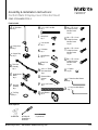
Assembly & Installation Instructions:
Conform Static 5 Display 2 over 3 Monitor Mount
CONF-ST523-30PB-TPCG-S
Parts Included
Tools Required:
Cordless Drill ⅜" pilot drill bit
#3 Phillips Bit
Screwdriver or
Driver/Drill
C Support Ring
Qty: 3
D Triple Arm
Assembly
Qty: 1
G Trim Ring
Qty: 3
H ⅜-16 × 3.50"L Hex Bolt
Qty: 1
K ⅜" Washer
Qty: 1
I Clamp Knob
Qty: 1
J ⅜-16 Hex Nut
Qty: 1
A 30" Pole Base
Qty: 1
B Clamp Cover
Qty: 1
L Clamp Bracket
Qty: 1
O Grommet Mount
Channel
Qty: 1
M Clamp Pad
Qty: 1
R M4 × 0.7P × 8 mm
Phillips Pan Head
Machine Screw
Qty: 20
S M4 × 0.7P × 12 mm
Phillips Pan Head
Machine Screw
Qty: 20
Q Quick Release
Qty: 6
T
M4 × 0.7P × 18 mm
Phillips Pan Head
Machine Screw
Qty: 20
U
M4 × 0.7P × 20 mm
Phillips Pan Head
Machine Screw
Qty: 20
V
⅜" Spacer
Qty: 20
W
⅛" Short Arm Allen Wrench
Qty: 1
X
3⁄16" Long Arm Allen Wrench
Qty: 1
P ⅜-16 × 4.50"L Stud
Qty: 1
E Single Monitor
Mount
Qty: 2

2 of 5 Workrite Ergonomics | 800.959.9675 www.workriteergo.com
Tighten
Cable
Managers
OPTIONAL
ROTATION
LIMITER
Tighten
Cable
Managers
OPTIONAL
ROTATION
LIMITER
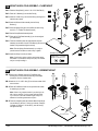
Place the Clamp Knob (I) on the ⅜-16 × 3.50"L Hex Bolt (H)
Place the ⅜ Washer (K) onto the Hex Bolt (H)
Install the ⅜ Hex Nut (J) onto the Hex Bolt (H) and tighten to
hold the knob in place
Install the Bolt and Knob assembly into the Clamp
Bracket (L)
Attach the Clamp Pad (M) to the Hex Bolt as shown using
the 6-32 × 5⁄16" Phillips Pan Head Screw (N)
Set the Clamp Bracket Assembly aside
Place the 30" Pole Base Assembly (A) on the rear edge of
your worksurface
From the underside, place the clamp bracket and knob
assembly into the slots of the 30" Pole Base (A). Be sure the
bracket is fully seated and tighten securely
Note: Place the Clamp Bracket Assembly up as high as
possible into the Pole Base to make it easy to tighten
Install the Clamp Cover (B) as shown
Note: If your desk is against a wall or panel system where
the bracket is not visible the Clamp Cover (B) is not needed
and you can skip installing it
Remove the L-Bracket from the 30" Pole Base (A) by
removing the 2 screws from the base using a #3 Phillips
screwdriver. Set the L-bracket aside
Install the ⅜-16 × 4.50"L Stud (P) into the base at least 8 full
turns as shown
Place the Pole Base & Stud into the grommet hole location
for attaching to your desk
Note: If there is no grommet location in your desk you can
drill a hole as small as ⅜" using a power drill and drill bit
or you can use a hole saw and drill a larger hole up to 3"
diameter to install the grommet mount option
From the underside, place the Grommet Mount Channel (M)
onto the Stud (P) with the “U” facing up as shown. Place the
⅜ Washer (K) and the ⅜-16 Hex Nut (J) onto the Stud (P)
and tighten securely
MOUNT BASE & POLE ASSEMBLY—CLAMP MOUNT
MOUNT BASE & POLE ASSEMBLY—GROMMET MOUNT
1a.1
1b.1
1a.2
1a.3
1a.4
1a.5
1a.6
1a.7
1a.8
1a.9
1b.2
1b.3
1b.4
1a
1a
1b
A
P
A
B
L-Bracket
1a.1
1a.2
1a.3
1a.4
1a.5
1b.1 1b.2
1b.4
1a.8
1a.9
N 6-32 × 5⁄16" Phillips
Pan Head Screw
Hardware at actual size
L
I
H
J
K
N
M
P
M
J
K
Grommet Hole
1b.3
A
1a.7

Workrite Ergonomics | 800.959.9675 www.workriteergo.com 3 of 5
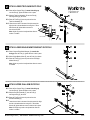
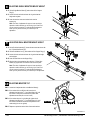
Place the rst Support Ring (C) smooth side facing up
onto the Pole (A), tighten the knob to lock in place
Slide the Triple Arm Assembly (D) onto the Pole (A)
and Support Ring (C) as shown
Place the Trim Ring (G) onto the pole and into the
Triple Arm Assembly (D)
Locate the two holes in the rear of the triple mount hub.
Align the hub to the workstation then using the ⅛" Short
Allen Wrench (W) tighten both set screws to
lock the hub in place
Note: Height may need to be adjusted later after the
monitor is installed
ATTACH LOWER TRIPLE ARM ONTO POLE
2.1
2.2
2.3
2.4
2
Place a Support Ring/Cable Manager (C) smooth side
facing up onto the Pole (A), tighten the knob to lock in place
Slide a Single Monitor Mount (E) onto the Pole (A) as shown
Place the Trim Ring (G) onto the pole and into the Single
Monitor Mount (E)
Note: Height may need to be adjusted later after the monitor
is installed
Place the rst Support Ring (C) smooth side facing up
onto the Pole (A), tighten the knob to lock in place
Slide the Dual Arm Assembly (F) onto the Pole (A)
and Support Ring (C) as shown
Place the Trim Ring (G) onto the pole and into the
Dual Arm Assembly (F)
Locate the two holes in the rear of the triple mount hub. Align
the hub to the workstation then using the ⅛" Short Allen
Wrench (W) tighten both set screws to lock the hub in place
Note: Arm height may need to be adjusted later after the
monitor is installed
ATTACH LOWER SINGLE MONITOR MOUNT ONTO POLE
ATTACH UPPER DUAL ARM ONTO POLE
3.1
4.1
3.2
4.2
3.3
4.3
4.4
3
4
C
C
D
D
D
F
G
A
2.1
2.2
2.3
Knob
W
2.4
Set Screws
E
C
A
A
G
G
3.1
4.1
4.2
4.3
3.2
3.3

4 of 5 Workrite Ergonomics | 800.959.9675 www.workriteergo.com
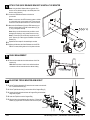
Note: Using the Quick Release Mount is optional. Your
monitor can be attached directly to the VESA plate of the
monitor mount if desired
Locate the VESA Mount Pattern on the back of
your monitor
Note: In some cases, the VESA mounting pattern is hidden
by a removable cover or the monitor base. These must be
removed to install the Quick Release or mount the monitor
Mount the Quick Release (Q) to the VESA mount on your
monitor as shown with four (4) M4 Screws either (R), (S),
(T) or (U) and tighten securely
Note: Always use the shortest screws possible to avoid
damaging the display by using screws that are too long
Note: In some case your monitor may require the use of
the ⅜" Spacers (V) to allow proper installation of the Quick
Release (Q)
Repeat the above steps for the remaining 4 monitors
Aligning the Monitors with Quick Release onto the VESA
Plate on the arms, sliding down to lock in place as shown
ATTACH THE QUICK RELEASE BRACKET & INSTALL THE MONITOR
5.1
5.2
5.3
5.4
5
Place monitor cables into the cable retainers of the Pole
support ring
Note: Make sure there is slack in the cables that allows
movement to tilt and rotate the monitor without binding
CABLE MANAGEMENT
6.1
6
On the Triple Arm Assembly (D) loosen the set screws as should with
the ⅛" Short Allen Wrench (W)
Lift the Triple Monitor Arm (D) and monitors off the Support Ring (C)
Loosen the knob and raise or lower the Support Ring to the desired
height and re-tighten
Lower the Triple Arm onto the Support Ring
Align the hub to the workstation then using the ⅛" Short Allen
Wrench (W) tighten both set screws to lock the hub in place
ADJUSTING TRIPLE MONITOR ARM HEIGHT
7.1
7.2
7.3
7.4
7.5
7
or
Q
RU
ST
V
5.1
5.4
5.2
D
C
7.1
7.5
7.2 7.4
7.3
Knob
W
Set Screws
C

5 of 5 Workrite Ergonomics | 800.959.9675 www.workriteergo.com
1500549 Rev A
X
Tilt Adjustment Bolt
10.1
10.2–10.3
On the Dual Arm Assembly (F) loosen the set screws as shown with
the ⅛" Short Allen Wrench (W)
Lift the Dual Monitor Arm (F) and monitors off the Support Ring (C)
Loosen the knob and raise or lower the ring to the desired height
and re-tighten
Lower the Dual Arm onto the Support Ring
Align the hub to the workstation then using the ⅛" Short Allen
Wrench (W) tighten both set screws to lock the hub in place
Note: The order of adjustment for upper or lower arm height
depends on which direction you are moving, Up or Down, and
can be reversed as required. To make the height adjustment
easier you may want to remove your monitors prior to adjustment
Locate the tilt adjustment bolt on the Monitor Mount(s)
If the monitor tilt is too difcult to tilt loosen the tilt
adjustment bolt using the 3⁄16" Long Allen Wrench (X) until
the monitor is easy to tilt but still holds in position after
adjustments are made (do not over loosen)
If the monitor drops or is not holding tilt, tighten the tilt
adjustment bolt using the 3 ⁄16" Long Allen Wrench (X) until
the monitor holds tilt but still allows tilt adjustments to be
made easily (do not over tighten)
Repeat as required to set the tilt for all mounted monitors
ADJUSTING DUAL MONITOR MOUNT HEIGHT
ADJUSTING MONITOR TILT
9.1
9.2
9.3
9.4
9.5
10.1
10.2
10.3
10.4
9
10
Lift the Single Monitor Mount (E) and monitor off the Support
Ring (C)
Loosen the knob and raise or lower the ring to the desired
height and re-tighten
Lower the monitor mount and monitor back onto the
support ring
Note: The order of adjustment for upper or lower arm height
depends on which direction you are moving, Up or Down, and
can be reversed as required. To make the height adjustment
easier you may want to remove your monitors prior to
adjustment
ADJUSTING SINGLE MONITOR MOUNT HEIGHT
8.1
8.2
8.3
8
9.2
9.3
9.3
F
C
E
8.1 8.3
8.2
-
 1
1
-
 2
2
-
 3
3
-
 4
4
-
 5
5


Workrite Conform ST 523 Installation guide
- Category
- Flat panel desk mounts
- Type
- Installation guide
Ask a question and I''ll find the answer in the document
Finding information in a document is now easier with AI