Sanyo LNS-W32 User manual
- Category
- Projection lenses
- Type
- User manual
This manual is also suitable for
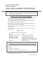
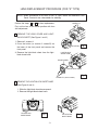
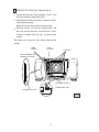
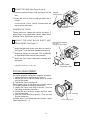
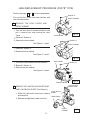
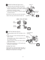
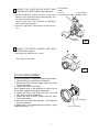
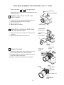
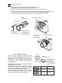
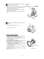
The Sanyo LNS-W32 Wide-angle Lens with a focal length of 22.3 mm is designed to replace the standard lens in compatible LCD projectors. It offers a wider projection angle, allowing you to project images onto larger screens or from shorter distances. The lens features easy installation and adjustment, with clear instructions provided in the manual. It also includes a light-block sheet and base, screws, and drivers for a hassle-free replacement process. The lens is compatible with three different cabinet designs (Type A, B, and C), and the manual provides detailed instructions for each type.
The Sanyo LNS-W32 Wide-angle Lens with a focal length of 22.3 mm is designed to replace the standard lens in compatible LCD projectors. It offers a wider projection angle, allowing you to project images onto larger screens or from shorter distances. The lens features easy installation and adjustment, with clear instructions provided in the manual. It also includes a light-block sheet and base, screws, and drivers for a hassle-free replacement process. The lens is compatible with three different cabinet designs (Type A, B, and C), and the manual provides detailed instructions for each type.


-
 1
1
-
 2
2
-
 3
3
-
 4
4
-
 5
5
-
 6
6
-
 7
7
-
 8
8
-
 9
9
-
 10
10


Sanyo LNS-W32 User manual
- Category
- Projection lenses
- Type
- User manual
- This manual is also suitable for
The Sanyo LNS-W32 Wide-angle Lens with a focal length of 22.3 mm is designed to replace the standard lens in compatible LCD projectors. It offers a wider projection angle, allowing you to project images onto larger screens or from shorter distances. The lens features easy installation and adjustment, with clear instructions provided in the manual. It also includes a light-block sheet and base, screws, and drivers for a hassle-free replacement process. The lens is compatible with three different cabinet designs (Type A, B, and C), and the manual provides detailed instructions for each type.
Ask a question and I''ll find the answer in the document
Finding information in a document is now easier with AI
Related papers
-
Sanyo LNS-W31A User manual
-
-
-
Sanyo LNS-T33 User manual
-
-
-
-
-
Sanyo PLC-XF46N/E User manual
-