DeWalt DW831 TYPE 3 Owner's manual
- Category
- Power sanders
- Type
- Owner's manual
This manual is also suitable for

Questions? See us on the World Wide Web at www.dewalt.com
INSTRUCTION MANUAL
GUIDE D'UTILISATION
MANUAL DE INSTRUCCIONES
INSTRUCTIVO DE OPERACION, CENTROS DE SERVICIO Y POLIZA
DE GARANT[A. ADVERTENCIA: LEASE ESTE INSTRUCTIVO
ANTES DE USAR EL PRODUCTO.
®
DW831, DW840
5" (125mm) and 7" (180mm) Heavy Duty Angle Grinder
Rectifieuse coudee de service intensif de 127 mm (5 po) et 175 mm (7 po)
Esmeriladora angular para trabajo pesado de 127 mm (5") y 175 mm (7")

IF YOU HAVE ANY QUESTIONS OR COMMENTS ABOUT THIS
OR ANY DEWALT TOOL, CALL US TOLL FREE AT:
1-800-4-DEWALT (1-800-433-9258)
General Safety Instructions
_ WARNING! Read and understand all instructions.
Failure to follow all instructions listed below, may result
in electric shock, fire and/or serious personal injury.
SAVE THESE INSTRUCTIONS
WORK AREA
• Keep your work area clean and well lit. Cluttered benches
and dark areas invite accidents.
• Do not operate power tools in explosive atmospheres, such
as in the presence of flammable liquids, gases, or dust.
Power tools create sparks which may ignite the dust or fumes.
• Keep bystanders, children, and visitors away while operat-
ing a power tool Distractions can cause you to lose control
ELECTRICAL SAFETY
• Grounded tools must be plugged into an outlet properly
installed and grounded in accordance with all codes and
ordinances. Never remove the grounding prong or modify
the plug in any way. Do not use any adaptor plugs. Check
with a qualified electrician if you are in doubt as to whether
the outlet is properly grounded, ff the tools should electrical-
ly malfunction or break down, grounding provides a low resist-
ance path to carry electricity away from the user. Applicable
only to Class I (grounded) tools.
• Double insulated tools are equipped with a polarized plug
(one blade is wider than the other.) This plug will fit in a
polarized outlet only one way. ff the plug does not fit fully in
the outlet, reverse the plug. If # still does not fit, contact a
qualified electrician to install a polarized outlet. Do not
change the plug in any way. Double insu/ation [] e/iminates
the need for the three wire grounded power cord and grounded
power supply system. Applicable to Class II (double insu-
lated) tools.
Avoid body contact with grounded surfaces such as pipes,
radiators, ranges and refrigerators. There is an increased risk
of electric shock if your body is grounded.
Don't expose power tools to rain or wet conditions. Water
entering a power tool will increase the risk of electric shock.
Do not abuse the cord. Never use the cord to carry the tools
or pull the plug from an outlet. Keep cord away from heat,
oil, sharp edges or moving parts. Replace damaged cords
immediately. Damaged cords increase the risk of electric shock.
When operating a power tool outside, use an outdoor
extension cord marked "'W-A" or "'W." These cords are rated
for outdoor use and reduce the risk of electric shock. When
using an extension cord, be sure to use one heavy enough to
carry the current your product will draw. An undersized cord will
cause a drop in line voltage resulting in loss of power and over-
heating. The following table shows the correct size to use
depending on cord length and nameplate ampere rating, ff in
doubt, use the next heavier gage. The smaller the gage number,
the heavier the cord.
Minimum Gage for Cord Sets
Volts Total Length of Cord in Feet
120V 0-25 26-50 51-100 101-150
Ampere Rating
More Not more AWG
Than Than
12 16 14 12 Not Recommended

PERSONAL SAFETY
• Stay alert, watch what you are doing and use common
sense when operating a power tool Do not use tool while
tired or under the influence of drugs, alcohol, or medica-
tion. A moment of inattention while operating power tools may
result in serious personal injury.
• Dress properly. Do not wear loose clothing or jewelry.
Contain long hair. Keep your hair, clothing, and gloves
away from moving parts. Loose clothes, jewelrjL, or long hair
can be caught in moving parts. Air vents often cover moving
parts and should also be avoided.
• Avoid accidental starting. Be sure switch is off before plug-
ging in. Carrying tools with your finger on the switch or plugging
in tools that have the switch on invites accidents.
• Remove adjusting keys or wrenches before turning the tool
on. A wrench or a key that is left attached to a rotating part of
the tool may result in personal injury
• Do not overreach. Keep proper footing and balance at all
times. Proper footing and balance enables better control of the
tool in unexpected situations.
• Use safety equipment. Always wear eye protection. Dust
mask, non-skid safety shoes, hard hat, or hearing protec-
tion must be used for appropriate conditions.
TOOL USE AND CARE
• Use clamps or other practical way to secure and support
the workpiece to a stable platform. Holding the work by hand
or against your body is unstable and may lead to loss of control.
• Do not force tool Use the correct tool for your application.
The correct tool will do the job better and safer at the rate for
which # is designed.
• Do not use tool ff switch does not turn # on or off. Any tool
that cannot be controlled with the switch is dangerous and must
be repaired.
• Disconnect the plug from the power source before making
any adjustments, changing accessories, or storing the tooL
Such preventative safety measures reduce the risk of starting
the tool accidentally.
• Store idle tools out of reach of children and other untrained
persons. Tools are dangerous in the hands of untrained users.
• Maintain tools with care. Keep cutting tools sharp and
clean. Properly maintained tools, with sharp cutting edges are
less likely to bind and are easier to control
• Check for misalignment or binding of moving parts, break-
age of parts, and any other condition that may affect the
tools operation. If damaged, have the tool serviced before
using. Many accidents are caused by poorly maintained tools.
• Use only accessories that are recommended by the manu-
facturer for your model Accessories that may be suitable for
one tool may become hazardous when used on another tool
SERVICE
• Tool service must be performed only by qualified repair
personneL Service or maintenance performed by unqualified
personnel could result in a risk of injury
• When servicing a tool, use only identical replacement parts.
Follow instructions in the Maintenance section of this man-
ual Use of unauthorized parts or failure to follow maintenance
instructions may create a risk of electric shock or injury.
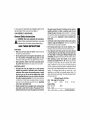
Additional Specific Safety Instructions
for Grinders
• Always use proper guard with grinding wheel. A guard pro-
tects operator from broken wheel fragments and wheel contact.
• Accessories must be rated for at least the speed recom-
mended on the tool warning label Wheels and other
accessories running over rated speed can fly apart and cause

injury.Accessoryratingsmustalwaysbeabovetoolspeedas
shownontoolnameplate.
• Hold tool by insulated gripping surfaces when performing
an operation where the cutting tool may contact hidden
wiring or its own cord. Contact with a "live" wire will make
exposed metal parts of the tool "live" and shock the operator.
• Do not use Type 11 Flaring Cup wheels on this tooL Using
inappropriate accessories can result in injury.
• Before using, inspect recommended accessory for cracks or
flaws. If such a crack or flaw is evident, discard the accessory
The accessory should also be inspected whenever you think the
tool may have been dropped. Flaws may cause wheel breakage.
• When starting the tool with a new or replacement wheel, a
new or replacement wire brush installed, or if you are
unsure of the condition of the wheel, hold the tool in a well
protected area and let it run for one minute, ff the wheel has
an undetected crack or flaw, it should burst in less than one
minute. If the wire brush has loose wires, they will be detected.
Never start the tool with a person in line with the wheel This
includes the operator.
• Avoid bouncing the wheel or giving # rough treatment. If this
occurs, stop the tool and inspect the wheel for cracks or flaws.
• Direct sparks away from operator, bystanders or flammable
materials. Sparks may be produced while using a sander or
grinder. Sparks may cause bums or start fires.
• Always use side handle. Tighten the handle securely. The
side handle should always be used to maintain control of the
tool at all times.
• Clean out your tool often, especially after heavy use. Dust
and grit containing metal particles often accumulate on interior
surfaces and could create an electric shock hazard.
• Do not operate this tool for long periods of time. Vibration
caused by tool action may be harmful to your hands and arms.
Use gloves to provide extra cushion and limit exposure by taking
frequent rest periods.
WARNING: Some dust created by power sanding, sawing, grind-
ing, drilling, and other construction activities contains chemicals
known to cause cancer, birth defects or other reproductive harm.
Some examples of these chemicals are:
• lead from lead-based paints,
• crystalline silica from bricks and cement and other masonry
products, and
• arsenic and chromium from chemically-treated lumber
(CCA).
Your risk from these exposures varies, depending on how often you
do this type of work. Toreduce your exposure to these chemicals:
work in a well ventilated area, and work with approved safety equip-
ment, such as those dust masks that are specially designed to fil-
ter out microscopic particles.
• Avoid prolonged contact with dust from power sanding,
sawing, grinding, drilling, and other construction activi-
ties. Wear protective clothing and wash exposed areas with
soap and water. Allowing dust to get into your mouth, eyes, or
lay on the skin may promote absorption of harmful chemicals.
A WARNING: Use of this tool can generate and/or disburse dust,
which may cause serious and permanent respiratory or other injury
Always use NIOSH/OSHA approved respiratory protection appro-
priate for the dust exposure. Direct particles away from face and
body.
_CAUTION: Use extra care when grinding into a corner
because a sudden, sharp movement of the grinder may be experi-
enced when the wheel or other accessory contacts a secondary
surface.
CAUTION: Wear appropriate hearing protection during use.
Under some conditions and duration of use, noise from this prod-
uct may contribute to hearing loss.

Thelabelonyourtoolmayincludethefollowingsymbols.The
symbolsandtheirdefinitionsareasfollows:
V.......... volts A .......... amperes
Hz ............ hertz
min .......... minutes
........ direct current
[] .............. Class II Construction
_ .............. earthing terminal
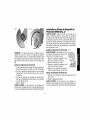
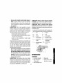
INTRODUCTION
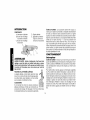
COMPONENTS
A. Trigger Switch
B. Lock-On Button
C. Spindle Lock Button
W .......... watts
"_ .......... alternating current
no .......... no load speed
.......... safety alert symbol
.../min ....revolutions per
minute
D. Side Handle
E. Guard (Type 27, open
beneath wheel or
accessory)
ASSEMBLY
_ CAUTION: Turn off and unplug the tool before making any
adjustments or removing or installing attachments or acces-
sories. Before reconnecting the tool, depress and release the
rear part of the switch to ensure that the tool is off.
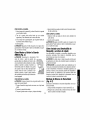
ATTACHING SIDE HANDLE
The side handle can be fitted to either side of the gear
case in the threaded holes, as shown. Before using the
tool, check that the handle is tightened securely.
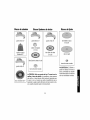
ACCESSORIES
It is important to choose the correct guards, backing
pads and flanges to use with grinder accessories. See
pages 5-6 for information on choosing the correct
accessories.
_},CAUTION: Accessories must be rated for at least the speed
recommended on the tool warning label Wheels and other acces-
sories running over their rated speed may fly apart and cause
injury. Threaded accessories must have a 5/8" - 11 hub. Every
unthreaded accessory must have a 7/8" arbor hole. ff it does not, it
may have been designed for a circular saw. Use only the acces-
sories shown on pages 5-6 of this manual Accessory ratings must
always be above listed tool speed as shown on tool nameplate.
OPERATION
Switch
i_ CAUTION: Check that the tool is not locked ON before connect-
ing it to a power supply, ff the trigger switch is locked ON when the
tool is connected to the power supply, it will start immediately.
Damage to your tool or personal injury may result.
To start the tool, squeeze the trigger switch (A). To turn the tool off,
release the switch. The tool can be locked on for continuous use by
holding the trigger switch depressed while you depress the switch
locking button next to the trigger. Hold the lock-on button (B) in as
you gently release the trigger. Release the locking button and the
tool will continue to run. To turn the tool off from a locked on condi-
tion, squeeze and release the trigger once.

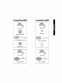
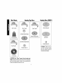
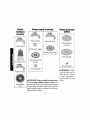
5" Grinding Wheels (DW831) 7" Grinding Wheels (DW840)
Type 27 guard
unthreaded backing flange
Type 27 depressed center wheel
threaded clamp nut
Type 27 guard
backing flange
Type 27 non-hubbed wheel
clamp nut
Type 27 guard
Type 27 hubbed wheel
Type 27 guard
Type 27 hubbed wheel

Wire Wheels
Sanding Flap Discs
Sanding Discs (DW831)
Type 27 guard
3" wire cup brush
Type 27 guard
4" wire wheel
Type 27 guard
unthreaded backing flange
non-hubbed sanding flap disc
threaded clamp nut
Type 27 guard
hubbed sanding flap disc
rubber backing pad
sanding disc
threaded clamp nut
.& WARNING: DW840 cannot be
used with conventional sanding
discs and backing pads due to
mismatched rated speeds.
_ CAUTION: Use a Type 27 guard with wire brushes and
wheels. Operators and others in the area should wear appropriate
eye, face and body protection. Strands of wire may break and fly
off when wire wheels and brushes are in use.

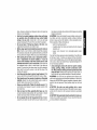
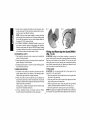
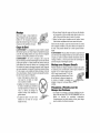
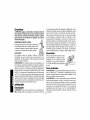
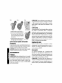
Grinding
Using a depressed center Type 27 wheel,
hold the tool at an angle of approximately
10°- 30° to the work for grinding. Most
Type 27 wheels are not designed for cut-
ting operations.
Edge Cutting
10° _ 30°
_, WARNING: Edge grinding and cutting can be performed only with
Type 27 wheels that are designed and specified for this purpose.
Protect yourseff during edge cutting by directing the open side of
the guard toward a surface.
i_ WARNING: Wheels used for cutting and edge grinding may
break or kick back ff they bend or twist while the tool is being used
to do cut-off work or deep grinding. To reduce the risk of serious
injury, lim# the use of these wheels with a standard Type 27 guard
to shallow cutting and notching (less than 1/2" in depth). The open
side of the guard must be positioned away from the operator.
1. Allow the tool to reach full speed before touching the tool to the
work surface.
2. Apply minimum pressure to the work surface, allowing the
tool to operate at high speed. Grinding
rate is greatest when the tool operates
at high speed.
3. Position yourself so that the open-
underside of the wheel is facing away
from you.
4. Once a cut is begun and a notch is
established in the workpiece, do not
change the angle of the cut. Changing
the angle will cause the wheel to bend
and may cause wheel breakage.
5. Remove the tool from the work surface before turning the tool
off. Allow the tool to stop rotating before laying it down.
Edge grinding and cutting wheels should contact the work surface
only at the edge of the wheel, not on the top or bottom ofthe wheel.
Side pressure on the wheel could lead to breakage of the wheel.
_ WARNING: Do not use edge grinding/cutting wheels for surface
grinding applications because these wheels are not designed for
side pressures encountered with surface grinding. Wheel breakage
and injury may result.
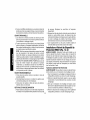
Sanding With Abrasive Discs
When using an abrasive disc and rubber backing pad, hold the tool
so that an angle of 10° to 15° exists between the disc and the
work, as shown. Using an angle of 5°to 15°
will allow you to produce a smooth surface.
If only the outer edge of the sanding disc is
pressed flat against the work, the sanding
action will be irregular and bumpy, and the 1s°
tool will be difficult to control.
Precautions To Take When
Removing Paint
1. Sanding or wire brushing lead based paint is NOT RECOM-
MENDED due to the difficulty of controlling the contaminated
dust. The greatest danger of lead poisoning is to children and
pregnant women.
2. Since it is difficult to identify whether or not a paint contains lead
without a chemical analysis, we recommend the following pre-
cautions when sanding any paint:
PERSONAL SAFETY
1. No children or pregnant women should enter the work area
where the paint sanding is being done until all clean up is
completed.

2.Adustmaskorrespiratorshouldbewornbyallpersonsenter-
ingtheworkarea.Thefiltershouldbereplaceddailyorwhen-
everthewearerhasdifficultybreathing.
NOTE:Onlythosedustmaskssuitableforworkingwithlead
paintdustandfumesshouldbeused.Ordinarypaintingmasks
donotofferthisprotection.Seeyourlocalhardwaredealerfor
theproperN.I.O.S.H.approvedmask.
3.NOEATING,DRINKINGorSMOKINGshouldbedoneinthe
workareatopreventingestingcontaminatedpaintparticles.
WorkersshouldwashandcleanupBEFOREeating,drinking
orsmoking.Articlesoffood,drink,orsmokingshouldnotbeleft
intheworkareawheredustwouldsettleonthem.
ENVIRONMENTALSAFETY
1.Paintshouldberemovedinsuchamannerastominimizethe
amountofdustgenerated.
2.Areaswherepaintremovalisoccurringshouldbesealedwith
plasticsheetingof4milsthickness.
3.Sandingshouldbedoneinamannertoreducetrackingofpaint
dustoutsidetheworkarea.
CLEANINGANDDISPOSAL
1.Allsurfacesintheworkareashouldbevacuumedandthor-
oughlycleaneddailyforthedurationofthesandingproject.
Vacuumfilterbagsshouldbechangedfrequently.
2.Plasticdropclothsshouldbegatheredupanddisposedof
alongwithanydustchipsorotherremovaldebris.Theyshould
beplacedinsealedrefusereceptaclesanddisposedofthrough
regulartrashpick-upprocedures.
Duringcleanup,childrenandpregnantwomenshouldbekept
awayfromtheimmediateworkarea.
3.Alltoys,washablefurnitureandutensilsusedbychildren
shouldbewashedthoroughlybeforebeingusedagain.
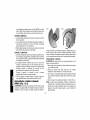
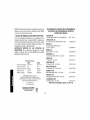
FIG. 1 FIG. 2
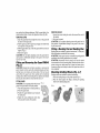
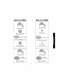
Fitting and Removing the Guard DW831
(Fig. 1 & 2)
ACAUTION: Unplug the tool before mounting or removing the
guard. Guards must be used with aft grinding wheels and sanding
flap discs, wire brushes and wire wheels. The tool may be used
without the guard only when sanding with conventional sanding
discs. Before reconnecting the tool, depress and release the rear
part of the switch to ensure that the tool is off.
FITTING GUARD
_CAUTION: Do not operate grinder with a loose guard or the
guard latch in the open position.
1. Open the guard latch (A) and align the arrow on the guard with
the arrow on the gear case.
2. Push the guard down until the guard lugs engage and rotate
freely in the groove on the gear case.
3. With the guard latch open, rotate the guard into the working
position providing maximum protection to the user (Fig. 2).
4. Close the guard latch to secure guard on gear case (Fig. 2).
NOTE: The guard is pre-adjusted to the diameter of the spindle hub
at the factory. If the guard needs further adjustment after a period of

use,performthefollowingadjustment.Withtheguardlatchinthe
closedpositiontightenorloosentheadjustmentscrew(Fig.2B).
REMOVINGGUARD
1.Opentheguardlatch(A)andalignthearrowontheguardwith
thearrowonthegearcase.
2.Pulltheguardupuntiltheguardlugsengageandrotatefreely
inthegrooveonthegearcase.
3.Withtheguardlatchopen,rotatetheguarduntilthearrowsare
aligned.(Fig.2).
4.Removetheguard.
_CAUTION:Do not tighten adjusting screw with guard latch in
open position. Undetectable damage to the guard or the mount-
ing hub may result.
Fitting and Removing the Guard DW840
(Fig. 3)
_CAUTION: Unplug the tool before mounting or removing the
guard. Guards must be used with all grinding wheels and sand-
ing flap discs, wire brushes and wire wheels. The tool may be
used without the guard only when sanding with conventional
sanding discs. Before reconnecting the tool, depress and release
the rear part of the switch to ensure that the tool is off.
FITTING GUARD
_,CAUTION: Do not operate grinder with a loose FIG. 3
guard or the guard latch in the open position.
1. Place the angle grinder on a table, spindle up.
2. Press the guard down.
3. Position the guard between your body and
the work piece.
4. Tighten the screw holding the cinch collar
firmly around the neck of the spindle.
REMOVING GUARD
1. Loosen the screw holding the cinch collar around the neck of
the spindle.
2. Lift up on the guard.
ACAUTION: Do not tighten adjusting screw with guard latch in
open position. Undetectable damage to the guard or the mount-
ing hub may result.
Fitting a Backing Pad and Sanding Disc
Backing pads are available as optional accessories. To fit the pad,
follow instructions provided with the accessory.
CAUTION: Proper guard must be re-installed for grinding wheel
applications after sanding applications are complete.
J_CAUTION: Accessories must be rated for at least the speed
recommended on the tool warning label Wheels and other acces-
sories running over rated speed can fly apart and cause injury.
Accessory ratings must always be above tool speed as shown on
tool nameplate.
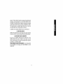
Mounting Grinding Wheels (Fig. 4-7)
Grinding wheels are available as optional accessories.
1. Place the backing flange on the grinder spindle (Fig. 4).
2. Place the wheel against the flange, centering the grinding
wheel on the backing flange pilot.
FIG. 4 FIG. 5 FIG. 6

3. Screw the threaded flange onto the
spindle (Fig. 5).
4. Rotate the spindle by hand while press-
ing the spindle lock button (Fig. 6) until
the spindle locks, preventing the spin-
dle from rotating.
5. Securelytighten the threaded flange with FIG.7
the supplied spanner wrench (Fig. 7).
Fitting Wire Cup Brushes
The wire cup brush screws directly on the spindle of the machine
without the use of flanges. AType 27 guard is required when using
wire brushes or wheels.
CAUTION: Wear work gloves when handling wire cup brushes.
Wire brushes can become sharp.
MAINTENANCE
Cleaning
_, WARNING: Blow dust and grit out of the motor housing regularly
using clean, dry compressed air. Dust and grit containing metal
particles often accumulate on interior surfaces and could create an
electrical shock hazard if not frequently cleaned out. ALWAYS
WEAR SAFETY GLASSES.
_,CAUTION: Never use solvents or other harsh chemicals for
cleaning the non-metallic parts of the tooL These chemicals may
weaken the plastic materials used in these parts. Use a cloth damp-
ened only with water and mild soap.
Lubrication
DEWALT tools are properly lubricated at the factory and are ready
for use. Tools should be relubricated regularly every sixty days to six
months, depending on usage. (Tools used constantly on production
or heaw-duty jobs and tools exposed to heat may require more
10
frequent lubrication.) This lubrication should only be attempted by
trained power tool repair persons, such as those at DEWALT serv-
ice centers or by other qualified service personnel.
Motor Brushes
When brushes become worn, the tool will automatically stop and
prevent damage to the motor. Brush replacement should be per-
formed by DEWALT authorized service centers.
Accessories
Recommended accessories for use with your tool are available at
extra cost from your local dealer or authorized service center. If you
need assistance in locating any accessory for your tool, contact:
DEWALT Industrial Tool Co., 701 East Joppa Road, Baltimore, MD
21286.
,Z_,CAUTION: Accessories must be rated for at least the speed
recommended on the tool warning label Wheels and other acces-
sories running over rated speed can fly apart and cause injury.
Accessory ratings must always be above tool speed as shown on
tool nameplate.
ACAUTION: The use of any other accessory not recommended
for use with this tool could be hazardous.
Repairs
To assure product SAFETY and RELIABILITY, repairs, mainte-
nance and adjustment should be performed by authorized service
centers or other qualified service personnel. Always use identical
replacement parts.
Three Year Limited Warranty
DEWALT will repair, without charge, any defects due to faulty mate-
rials or workmanship for three years from the date of purchase.
This warranty does not cover part failure due to normal wear or tool

abuse.Forfurtherdetailofwarrantycoverageandwarrantyrepair
information,visitwww.dewalt.comorcall1-800-4-DEWALT(1-800-
433-9258).Thiswarrantydoesnotapplytoaccessoriesordamage
causedwhererepairshavebeenmadeorattemptedbyothers.
Thiswarrantygivesyouspecificlegalrightsandyoumayhave
otherrightswhichvaryincertainstatesorprovinces.
Inadditiontothewarranty,DEWALTtoolsarecoveredbyour:
1YEARFREESERVICE
DEWALTwillmaintainthetoolandreplacewornpartscausedby
normaluse,forfree,anytimeduringthefirstyearafterpurchase.
90 DAY MONEY BACK GUARANTEE
If you are not completely satisfied with the performance of your
DEWALT Power Tool, Laser, or Nailer for any reason, you can
return it within 90 days from the date of purchase with a receipt for
a full refund - no questions asked.
FREE WARNING LABEL REPLACEMENT: Ifyour warning labels
become illegible or are missing, call 1-800-4-DEWALT for a free
replacement.
11
Page is loading ...
Page is loading ...
Page is loading ...
Page is loading ...
Page is loading ...
Page is loading ...
Page is loading ...
Page is loading ...
Page is loading ...
Page is loading ...
Page is loading ...
Page is loading ...
Page is loading ...
Page is loading ...
Page is loading ...
Page is loading ...
Page is loading ...
Page is loading ...
Page is loading ...
Page is loading ...
Page is loading ...
Page is loading ...
Page is loading ...
Page is loading ...
Page is loading ...

DEWALTIndustrialToolCo,,701EastJoppaRoad,Baltimore,MD21286(OCT04)FormNo,392424-02DW831,840
Copyright©2003, 2004 DEWALT
The following are trademarks for one or more DEWALT power tools: the yellow and black color scheme; the "D" shaped air intake grill; the
array of pyramids on the handgrip; the kit box configuration; and the array of lozenge-shaped humps on the surface of the tool.
-
 1
1
-
 2
2
-
 3
3
-
 4
4
-
 5
5
-
 6
6
-
 7
7
-
 8
8
-
 9
9
-
 10
10
-
 11
11
-
 12
12
-
 13
13
-
 14
14
-
 15
15
-
 16
16
-
 17
17
-
 18
18
-
 19
19
-
 20
20
-
 21
21
-
 22
22
-
 23
23
-
 24
24
-
 25
25
-
 26
26
-
 27
27
-
 28
28
-
 29
29
-
 30
30
-
 31
31
-
 32
32
-
 33
33
-
 34
34
-
 35
35
-
 36
36
-
 37
37
-
 38
38


DeWalt DW831 TYPE 3 Owner's manual
- Category
- Power sanders
- Type
- Owner's manual
- This manual is also suitable for
Ask a question and I''ll find the answer in the document
Finding information in a document is now easier with AI
in other languages
Related papers
Other documents
-
Epson D28114 User manual
-
Quantum G950 User manual
-
Black & Decker Angle 7750 User manual
-
-
Craftsman 172.11502 User manual
-
Bosch 3814 Owner's manual
-
-
Hitachi G13SC2 Owner's manual
-
Wen 2900 Owner's manual
-
Panasonic MC-UG327-00 Owner's manual