Page is loading ...

Installation Instructions B351
Ursa Outdoor Sconces 302501D & 302503D Page 1 of 4
Modern American Blacksmiths | Fine, Hand-Crafted Lighting
Castleton, Vermont USA | HUBBARDTONFORGE.COM 34411
Please Note: This fixture is designed to be mounted on a standard wall surface and may not be suitable for all
applications. Sconces are to be mounted 4 feet above ground. If installing in a
non-wood frame application, we recommend consulting a qualified builder or
electrician.
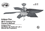
To Mount Fixture to Wall (Figures 1 thru 3)
Component Parts
A Fixture Assembly
B Mounting Bracket
C #8 Black Screws (4)
D Rubber Washer (2)
E Green Ground Screw
F Cupped Washer
G Caulking Lip
H Decorative Assembly
I Black Screws (2)
Caution: Be sure power is off at the main breaker box prior to installation.
1. Carefully unpack the fixture from the carton.
2. Using two machine screws (not provided) fasten the mount
bracket (B) to the electric box.
Note: A new electric box comes with screws. When
replacing an existing fixture, retain screws for use with
the new fixture.
3. To aid in installation of the fixture assembly (A),
remove decorative assembly (H) by removing the
two black screws (I). Figure 1.
Note: Decorative assembly is shipped installed.
4. Hold the fixture assembly (A) close to the wall
mount bracket and using suitable wire connectors
(not provided), connect fixture wires to supply
wires (white to white and black to black). Ground
the mounting bracket using the green ground
screw (E) and cupped washer (F) to secure a
pigtail lead to the bracket and connect all ground
wires (bare copper or green to bare copper or
green).
Caution: Make sure wire connectors are twisted on
securely, and no bare wires are exposed.
(continued)
CAUTION: FAILURE TO INSTALL THIS FIXTURE PROPERLY MAY RESULT IN SERIOUS PERSONAL
INJURY OR DEATH AND PROPERTY DAMAGE. We recommend installation by a licensed electrician.
This product must be installed in accordance with applicable installation code(s), by a person familiar with the
construction and operation of the product and the hazards involved.*
Caution: Do not exceed maximum wattage noted on fixture. Use only recommended bulbs with fixture.
(Figure 1)
(Figure 2)

Installation Instructions B351
Ursa Outdoor Sconces 302501D & 302503D Page 2 of 4
Modern American Blacksmiths | Fine, Hand-Crafted Lighting
Castleton, Vermont USA | HUBBARDTONFORGE.COM 34411
5. Apply a generous bead of a suitable caulking
material (not provided) to caulking lip (G) on
the fixture. Caulk should be applied around
the entire perimeter of the back (Figure 3)
6. Carefully tuck all wires behind the fixture
assembly (A) and inside the wall mount
bracket. Place the fixture firmly onto bracket
(B) and fasten with two #8 black screws (C)
and rubber washers (D) on top.
7. Install the two remaining black screws (C) in
bottom of fixture attaching to wall mounting
bracket (B).
To Install Glass (Figures 4 & 5)
Component Parts
H Decorative Assembly
J Glass
K Bottom Bracket
L Set Screw
1. Carefully slide glass (J) into decorative
assembly (H) until it settles into bottom
bracket (K). Figure 4.
Note: Be sure not to drop glass (J) into
bottom bracket (K) as glass (J) could chip
from the force.
2. Using hex wrench (provided), tighten set
screw (L) in bottom bracket (K) until snug
against glass (J). Be sure not to overtighten.
(Figure 5)
(continued)
(Figure 3)
(Figure 4)
(Figure 5)

Installation Instructions B351
Ursa Outdoor Sconces 302501D & 302503D Page 3 of 4
Modern American Blacksmiths | Fine, Hand-Crafted Lighting
Castleton, Vermont USA | HUBBARDTONFORGE.COM 34411
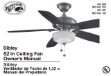
To Complete Installation (Figures 6 thru 8)
Component Parts
A Fixture Assembly
H Decorative Assembly
I Black Screws (2)
J Glass
M Spacer Assembly
N Bottom Rod
O Adjustment Screw
P #10 Screws (2)
1. Using the diagram in figure 7, place a mark on
the wall to locate the spacer assembly (M).
2. Hold spacer assembly (M) level on the wall and
using two #10 screws (P) provided in the kit bag;
fasten the spacer assembly (M) to the wall.
(Figure 7).
3. Place decorative assembly (H) up into fixture
assembly (A) while aligning bottom rod (N) with
spacer assembly (M) and re-install black screws
(I). (Figure6).
4. If adjustment is needed to hold decorative assembly
(H) parallel with wall, loosen adjustment screw (O),
move decorative assembly (H) to desired position
and retighten screw (O). (Figure 8)
Note: It is not necessary to completely remove
adjustment screw (O) from spacer assembly (M).
5. Restore electricity at main breaker.
(continued)
(Figure 6)

Installation Instructions B351
Ursa Outdoor Sconces 302501D & 302503D Page 4 of 4
Modern American Blacksmiths | Fine, Hand-Crafted Lighting
Castleton, Vermont USA | HUBBARDTONFORGE.COM 34411
If you need further assistance, or find that you are missing any parts, please contact the dealer from which you purchased
this product. We hope you enjoy your fixture!
* Hubbardton Forge will not be liable for injury or damage caused by improper installation, lamping or use of this fixture.
(Figure 7)
(Figure 8)
/