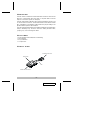
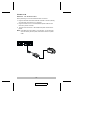
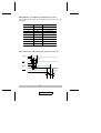
ATEN SXP500 is an interface converter that allows Centronics and RS-232 devices to communicate with each other. It provides a DB-9 RS-232C (DCE) compatible connector and a C-36 Centronics connector. The serial baud rate is from 1200 to 115200 bps., selectable by a combination of DIP Switch and Jumper settings. The parallel interface speed is 92.16 KB/sec. The unit supports both hardware and software (XON/XOFF) handshaking. Features include: both hardware and XON/XOFF handshaking, non-powered operation, easy installation, and compact size.
ATEN SXP500 is an interface converter that allows Centronics and RS-232 devices to communicate with each other. It provides a DB-9 RS-232C (DCE) compatible connector and a C-36 Centronics connector. The serial baud rate is from 1200 to 115200 bps., selectable by a combination of DIP Switch and Jumper settings. The parallel interface speed is 92.16 KB/sec. The unit supports both hardware and software (XON/XOFF) handshaking. Features include: both hardware and XON/XOFF handshaking, non-powered operation, easy installation, and compact size.


-
 1
1
-
 2
2
-
 3
3
-
 4
4
-
 5
5
-
 6
6
-
 7
7
-
 8
8
-
 9
9
-
 10
10
-
 11
11
-
 12
12


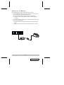
ATEN SXP500 is an interface converter that allows Centronics and RS-232 devices to communicate with each other. It provides a DB-9 RS-232C (DCE) compatible connector and a C-36 Centronics connector. The serial baud rate is from 1200 to 115200 bps., selectable by a combination of DIP Switch and Jumper settings. The parallel interface speed is 92.16 KB/sec. The unit supports both hardware and software (XON/XOFF) handshaking. Features include: both hardware and XON/XOFF handshaking, non-powered operation, easy installation, and compact size.
Ask a question and I''ll find the answer in the document
Finding information in a document is now easier with AI


