Craftsman 580.768050 User manual
- Category
- High-pressure cleaners
- Type
- User manual
This manual is also suitable for

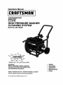
Operators Manual
[CRAFTSMAN"I
7.8 Horsepower
3000 PSI
2.5 GPM
HIGH PRESSURE WASHER
CLEANING SYSTEM
Model No. 580.768050
HOURS: Mon.- FH. 8 a.m. to 5 p.m. (CST)
CAUTION:
Before using this product, read this
manual and follow all its Safety Rules
and Operating Instructions.
Sears, Roebuck and Co., Hoffman Estates, IL 60179
Visit our Craftsman website: www.sears.com/craftsman
• Safety
• Assembly
• Operation
• Maintenance
• Parts
Part No. B3604 Draft 0 (2/2/99) printed in the U.S.A.

Warranty ................................ 2
Safety Rules ........................... 2--3
Assembly ............................... 4
Operation ............................. 5-9
Maintenance ......................... 10-15
Storage ................................ 16
Troubleshooting ......................... 17
Replacements parts .................... 19--27
EmissionControl
Warranty Statement .................... 28-29
How to orderparts and
requestservice .................... Backpage
LIMITED ONE YEAR WARRANTY ON CRAFTSMAN CLEANING SYSTEM
Forone year fromthe date of purchase,when thisCraftsmanCleaning System is maintainedand operated
accordingto the instructionsinthe owner'smanual,Sears will repair,free of charge, any defect in materialand
workmanship.
Ifthiswasher isused for commercialpurposes,this warrantyapplies for only 90 days from the date oi
purchase. Ifthiscleaningsystem isused for rentalpurposes,thiswarranty appliesfor only30 daysafterdate
of purchase.
LIMITED TWO YEAR WARRANTY ON CRAFTSMAN ENGINE
For twoyears from the date of purchase,when thisCraftsman engine is maintainedand operated accordingto
the instructionson the owner'smanual, Searswillrepair,free of charge, any defect in matadal and
workmanship.
Ifthe Craftsmanengine is usedfor commercialor rentalpurposes,this warranty appliesfor onlyone yearfrom
the date of purchase. •....
This warranty does not cover:. !
• Expendableitemssuch as spark plugs orair filters,whichbecome worn _udng norma!use_
• Repairs necessarybecause ofoperatorabuseor negligence,includingdamage resultingfromno water
being suppliedto pumpor failureto maintain the equipmentaccordingtothe instructionscontainedinthe
owner'smanual.
WARRANTY SERVICE IS AVAILABLE BY RETURNING THE HIGH CLEANING SYSTEM TO THE.
NEAREST SEARS SERVICE CENTER OR DEALER IN THE UNITED STATES. i _ _ - .
Thiswarrantygivesyou specificlegal dghtsand you may also have otherdghts, whichvary_m.mstate.t0 state.,
Sears, Roebuck and Co., Dept. 81TWA, Hoffman Estates, IL 60179 •
,_ CAU'FION: Beforeusingthis product,read this
manualand follow all Safety Rulesand
OperatingInstructions.
A
DANGER: When transporting,settingup,
adjustingor makingrepairstoyourcleaning
system,always disconnectthe spark plugwire
and place if where if cannotcontactthespark
plugtopreventaccidentalstarting.
Engine exhaust gasescontain DEADLY carbon
monoxidegas. This dangerous gas, if breathed in
sufficientconcentrations,can cause
unconsciousnessor even death. Operate this
equipmentonly in the open air where adequate
ventilationis available.
• Gasoline is highly FLAMMABLE and itsvaporsare
EXPLOSIVE. Do not permit smoking,open flames,
sparksor heat in the vicinitywhile handling
gasoline.Avoid spillinggasolineon a hotengine.
Allow unitto cool for 2 minutes before refueling.
Complywith all laws regulatingstorage and
handlingof gasoline.
• Locate this cleaningsystem in areas away from
combustiblematedals, combustiblefumes ordust.
2

• The highpressureequipmentis designedto be
used withSears authorizedpartsonly. Ifyou use
thisequipment with partsthat do not complywith
minimumspecifications,the userassumes all risks
and liabilities.
• Some chemicalsor detergentsmay be harmfulif
inhaledor ingested,causingsevere nausea,
faintingor poisoning.The harmfulelements may
cause propertydamage or severe injury.
• Do not allowCHILDREN to operatethe cleaning
systemat any time.
Operate engine onlyat govemed speed. Running
the engineat excessivespeeds increasesthe
hazard of personalinjury.Do nottamper withparts
whichmay increaseor decrease the governed
speed.
• Do not wear looseclothing,jewelry or anything
that may be caught inthe starteror other rotating
parts.
• Beforestartingthecleaningsystem in cold
weather,checkall parts ofthe equipmentand be
sure icehas notformedthere.
• Unitswithbrokenor missingparts,or without
protectivehousingor coversshouldNEVER be
operated.
• The muffler and air cleanermust be installedand
in goodconditionbefore operatingthe cleaning
system.These componentsact as spark arrestors
ifthe engine backfires.
• Check the fuel systemfor leaksor signsof
detedorationsuch as chafed or spongy hose,
looseormissingclamps or damaged tankor cap.
Correctall defectsbefore operatingthe cleaning
system.
• Do not sprayflammable liquids.
• Never allowany part of the bodytocome in
contactwiththe fluidstream. DO NOT come in
contactwith a fluid streamcreated by a leak in the
highpressurehose.
• High pressurestreams offluid this equipment
producescan pierceskin and its underlying
tissues,leadingto sedousinjuryand possible
amputation.
• Never aim the gunat people,animalsor plants.
• High pressurespraycan cause paint chipsor
otherparticlesto becomeairbome and fly at high
speeds.
• Alwayswear eye protectionwhen you use this
equipment or when you are in the vicinitywhere
the equipmentisin use.
• Operate the pressureat no morethan the PSI fluid
pressurerated for yourcleaningsystem.
Never move the machineby pullingon the high
pressure hose. Usethe handle providedon the
top of the unit.
Always be certainthe spraygun, nozzlesand
accessories are correctlyattached.
Never use a spraygunwhichdoes not havea
trigger lockor triggerguardin placeand in
workingorder.
Use a respiratoror maskwhenever there isa
chance that vaporsmay be inhaled.Read all
instructionswiththe mask so you are certainthe
mask will providethe necessary protectionagainst
inhalingharmfulvapors.
Highpressure spray may damage fragile items
includingglass. Do notpoint spray gunat glass
when in the jet spray mode.
Keep the hose connected to machineor the spray
gunwhilethe systemis pressurized.
Disconnectingthe hosewhilethe unitis
pressurizedisdangerous.
Holdthe spray gunfirmlyinyour handbeforeyou
startthe unit. Failureto do so couldresultin an
injuryfrom a whippingspraygun. Do not leavethe
spray gun unattendedwhilethe machine is ,
running.
The cleaningarea shouldhave adequateslopes
and drainageto reducethe possibility ofa fall due
to slipperysurfaces.
Keep water spray away from electricwiringor fatal
electdc shock_mayresult.
Do not secure triggergunin the pull-back(open)
position.
Do notby-pass any safety deviceon this machine.
The mufflerand engine heat up duringoperation
and remain hot immediatelyafter shuttingit doWn.
Avoid contact witha hot muffleror engineor you
could be severely bumed.
Operate and store this uniton a stable surface.
Always store cleaningsystemwiththe
Dial--a--CleanerTM knobinthe OFF position.
High pressure hosecan develop leaksfromwear,
kinking,abuse, etc.Water sprayingfrom a leak is
capable of injectingmatenal intoskin. Inspect
hose each time beforeusing it. Check all hosesfor
cuts, leaks, abrasionsor bulgingof cover,or
damage or movementof couplings.If any ofthese
conditions exist, replacehose immediately.Never
repair high pressurehose. Replace it withanother
hose that meats minimumpressureratingofyour
cleaningsystem.
I,_ LOOK FOR THIS SYMBOL TO POINT OUT IMPORTANT SAFETY PRECAUTIONS. IT I
I
MEANS "ATFENTIONI!! BECOME ALERT!!! YOUR SAFETY IS INVOLVED."
I
3

CARTON CONTENTS
The followingpartsare shippedloosewithyour
cleaningsystem:
• Main Unit-- cleaning systemwith wheels,
chemicaltanks, guide handle.
High Pressure Hose (already attached to pump)
• PartsBox (whichincludesitems listed below)
• Spray Gun
• Dual Lance with quickconnect nozzle fitting
• Engine Oil
• Three-peck of chemicalconcentrates
• Four multi-colored nozzles
• Manual Bag (whichincludesthe itemslisted
below)
• Owner's Manual
• Nozzle Cleaner Kit
• "O"--RingKit
• Tank Labels
Becomefamiliar with each piece before assembling
the cleaningsystem. Check all contentsagainst the
illustrationon Page 5. Ifany parts are missingor
damaged, call the PressureWasher Helpline at
1-800-222-3136.
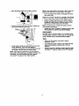
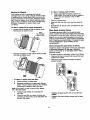
TO REMOVE CLEANING SYSTEM FROM
CARTON
• Remove loose partsand parts box includedwith
yourcleaningsystem.
• Slice twocorners at guide handle end of carton
fromtop to bottomso the panel can be folded
downflat.
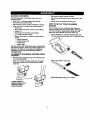
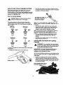
Uft the handle to
upright position and
slide the locking
caps Into place
• Raise guide handle, securein place.
Rollthe cleaningsystemout the openend of the
carton.
• Check carton for additionalloose parts.
HOW TO SET UP YOUR CLEANING
SYSTEM
Forthe mostpart, yourCraftsmanHighPressure
CleaningSystemhasbeen assembledat the facton].
You must,however,assemblethespraygun, and
attachthe highpressurehosetothe spraygun.
• Cutthe tiewrapson the highpressurehoseand
connecthighpressurehoseto gun.Tightenbyhand.
Attachdual lanceto spraygun.
• Place assembledspray gunon holder.
4

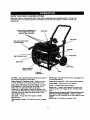
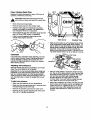
KNOW YOUR HIGH CLEANING SYSTEM
Read this owner's manual and safety rules before operating your cleaning system. Comparethe
illustrationswith your cleaning systemtofamiliarizeyourselfwith the locationsof variouscontrolsand
adjustments.
System Rinse, Detergent and
Chemical Reservoirs with
Internal Filter and Baffle
Spray Gun
Dual Lance with Quick-
Connect Fitting
GasTank
Air Filter
F
HighPressursHose PrimerBulb
Water Inlet
Dial-A-Cleaner'*
Selector Knob
Pressure
CommandTM
Pump
Oil Pill Cap
Air Filter - Dry type filterelement limitsthe amountof
dirtand dustthat gets in the engine.
DiaI-A-Clsaner TM Selector Knob - Selectsanyone
of three chemicals or the clean watersystem rinse.
Dual Lance with Quick-Connect Fitting- The dual
lance attachesto the spray gun and allowsyou to
switchfrom low pressure mode, for applying
chemicals,to high pressure mode, for cleaning.The
quick connectfittinglets you quicklyexchangethe four
provided nozzlesto adjustthe spray patternofthe
high pressurespray.
Gas Tank - Fill gas tank with regularunleaded
gasolinehera.
High Pressure Hose - Connect one end to thespray
gun.
OII Fill Cap - Fillengine withoilhere. See page 8 for
oil recommendations.
Pressure Command TM - Sets outputwater pressure.
Primer Bulb - Used to starta coldengine.
Pump - Developshighwater pressure.
Spray Gun - Controlsthe applicationof water onto
cleaningsurfacewith triggerdevice. Includessafety
latch.
System Rinse, Detergent and Chemical Reservoirs
with Internal Filter and Baffle - Usedto provide
detergentor otherchemicalsto the low pressurewater
stream.
Water inlet - Connectionfor garden hose.
5

HOW TO USE YOUR CLEANING SYSTEM
Read these instructionsand learn howto use your
cleaning system beforeyou attemptto startyour
cleaning system. If you have any problems operating
your cleaningsystem, please call the pressurewasher
helpUneat 1-800-222-3136.
How To Use the NozTJes
,_ DANGER: Never exchange nozzleswithout
lockingthe safetylatch on thetrigger.
The quick-connect on the dual lanceallowsyou
switch between four differentnozzles. The nozzles
vary the spray patternof the highpressurestreamas
shown below.
White Green
Yellow Red
too
In order t0 Changethe nozzle beingused,followthese
instructions:
Engage the safety latch on the spraygun.
Safety Latch
Pull backthe collaron the quickconnectand pull
the currentnozzle off;Store the nozzle in the space
providedon the controlpanel.
Note: For a more gentle rinse, selectthe 40* or 25"
degree nozzle. To scourthe surface,selectthe 15° or
0° nozzle.
• Pull backthe collar,insertthe new nozzle and
release the collar, makingsure itbecomes flush
with the end ofthe quickconnect. Pullon the
nozzle to make sure it is securelyin place.
Note: The chemicalnozzle ispermanentlyaffixedto
your dual lanceand has a spray pettem of25
degrees. Itmustbe used when applyingchemical.
• For mosteffectivecleaning, keep spray nozzle
between 8 to 24 inchesaway from cleaning
surface.
• Damage tothe surface may occur ifyou get the
spray nozzletoo clove to it.
Cleaning With The Nozzles ana ,_lying
Chemical
A
WARNING: You mustattachall hosesbefore
you startthe engine. Startingthe engine without
allthe hosesconnected and withoutthe water
turnedON willdamage the pump.
IMPORTANT: Use soaps designed specificallyfor
pressurewasher cleaningsystems.Household
detergentscoulddamage the pump.
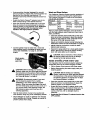
Up to three (3) differentsolutions can be carded onthe
cleaningsystemat one time. To applydetergentfollow
these steps:
• Dilutionis necessarywhen usingthe supplied
chemicalpackets, Simplysnipone comer of the
plastic pouch,pour the chemicalinto the tank, then
fill the tank with clean water. Label tanks with the
provided tank labels.
Pour chemical into one of
the tanks labeled A, B, C.
6

Ifusinganotherchemicaldesignedforusewith
pressurewashers,preparethechemicalsolutionas
requiredbythechemicalmanufacturer.Fill
chemicalreservoir(s)withthepreparedsolutionas
needed.
RotatetheDial-A-CleanerTM selector knobto the
letter correspondingtothe desired reservoir.
Open the chemicalvalve handle fully on thedual
lance byturningit countemlockwiseto place the
cleaningsystem in low pressure mode. Detergent
cannot be applied with the chemical valve
handle in the high pressure position.
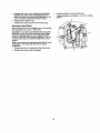
Wash and Rinse Surface
This CraftsmanCleaning System permitsregulationof
outputwater pressureby varyingthe enginespeed.
The PressureCommandTM found on the front panel
may be set, as follows:
Pressure Low to High
Duty Light Medium Heav"t
Application Auto Concrete Paint removal
Boat Driveway Degreasing
Furniture Deck
Afteryou haveapplieddetergent,scourthe surface
withthe highpressurewater streamand then rinseit
clean, as follows:
• Closethe chemicalvalve handlefullyon the dual
lance byturningit clockwiseto placethe cleaning
systemin highpressuremode. Chemicalwillnot
flow when in the highpressuremode.
Select and installthe desired nozzlefollowingthe
instructionson'How to Use the Nozzles"on page 6.
AdjustPressureCommancFMcontrol toobtain
• Connect garden hose to water inlet, checkthat desiredwater pressure.
high pressurehose is connected tospray gunand Expandthe spray patternfor a more gentlednsing
pump (see ASSEMBLY on page 4), and start action. Startat top ofarea to be dnsed,working.
engine, downwith same actionas for cleaning.
CAUTION: Test a small areaof thesurfaceto
be cleaned. Make surethere isno damage
Attachgarden caused bythe highpressurespray.
to hoseto
waterinlet
A
A
CAUTION: Beforestarting yourCleaning
System,make sure you have read and followed
the instructionsin the sections=BeforeStarting
the Cleaning System"on page 8 and "To Start
the Cleaning System"on page 8.
WARNING: Be extremely careful if you must
use thecleaning system from a ladder,
scaffoldingor any other relativelyunstable
location.When you pressthe trigger,the recoil
from the initial spray couldforce youtofall, or if
you are too close tothe cleaningsurface,the
high pressurespray couldforce you offa
climbingapparatus.
Start at lower portionof area to be washed and
work upward,using long,even overlappingstrokes.
Allowdetergent to 'soak in' (between 3-5 minutes)
before washingand rinsing.Reapply as neededto
preventsurface from drying.
RINSE SYSTE'_MAFTER EVERY USE
It is imperativethatthe chemicalselectorsystembe
rinsedafter each useto preventcloggingor leaks:
Fillthe System Rinsereservoirwithclean water.
Beforedisconnectingthewater supply,start your'
cleaningsystem.
A
CAUTION: Before startingyour Cleaning
System,makesure you have readand followed
the instructionsinthesections"Before Starting
the CleaningSystem"on page 8 and "To Start
the CleaningSystem"on page 8.
Open the chemicalvalve handlefullyon the dual
lance bytuming itcounterclockwiseto place the
cleaningsystemin low pressuremode.
Rotate the Dial-A-CleanerTM selectorknobto the
lettercorrespondingto the System Rinsetank. As
clean rinsewaterisdrawn throughthe system,
continuetheflow untilnodetergentfoam is
observed.
• Rotate the Dial-A-CleanerTM selector Imob to the
OFF position.

BEFORE STARTING THE CLEANING
SYSTEM
To operatetheengineyouwillneedtodothefollowing:
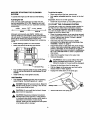
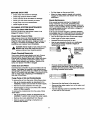
Add Engine Oil
only use high qualitydetergentoil ratedwith API
service classificationSF or SG. Selectthe oil'sSAE
viscositygrade accordingto yourexpected operating
temperature:
colder _ 32°F _ warmer
,,t II J,
5W30 SAE 30
Althoughmulti-viscosityoils(5W30, 10W30, etc.)
improve startingin coldweather, these multi-viscosity
oilswill resultin increasedoilconsumption when used
above 32°F. Check yourengine oil level more
frequentlyto avoidpossibledamage from runninglow
on oil.
Place cleaningsystemon a level surface
Clean area aroundoilfillcap and remove.
Dil Fill Cap
/
Oil Drain Plug
Pour oilfrom enclosedbottle intothe oilfillopening
untiloil reachesthe point of overflowing. Do not
overfill.
Install oilfillcap. Hand tightensecurely.
Add Gasoline
• Use regular unleaded gasolinewith thecleaning
system engine. Fueltank capacityis 1 gallon.
,_ DANGER: Never fillfuel tank indoors.Never fill
fueltankwhen engineis runningor hot.Do not
smokewhen fillingfuel tank.
,_ CAUTION: Do notoverfillthefuel tank. Always
leave roomfor expansion.
,&
CAUTION: Experienceindicatesthatalcohol
blendedfuels (calledgasoholor usingethanol
or methanol) can attract moisturewhichleadsto
separationandformationof acidsduring
storage.Acidicgas can damage thefuel system
ofan enginewhilein storage.
To add fuel toengine:
Clean area aroundfuel cap, removecap.
• Add regular unleaded gasoline,slowly,to the fuel
tank.
Important: Never mix oilwith gasoline.
• Install fuel cap and wipe up any spilledgasoline.
TO START THE CLEANING SYSTEM
The best way to startyourcleaningsystem engine for
the firsttime isto followthese instructionsstep-by-
step. This startinginformationalso applies whenever
you startthe engine afteryou have letthe cleaning
system sitidle for at least a day.
Place the cleaningsystem in an area close enough
to an outsidewater soume that canflow at a rate of
at least 3 gallonsper minute. Connect a garden
hose to the water spout.
• Check that the high pressurehose is tigh'tly
connectedto the spray gunand to the pump. See
ASSEMBLY sectionon page 4.
• Check inletscreen on the water inlet. If the screen
is dirty,clean beforeattachinga garden hose. ffthe
screen is damaged, do not connectto the garden
hose. Replacewith screen providedin maintenance
kitor cell 1-800-366-PART toorder a replacement
inlet screen.
• Attach thethe garden hose tothe water inlet.
• Tum on the water,
,& CAUTION_Do not runpumpwithoutthe water
supplyconnected and turned on. You must
follow this cautionor the pumpwillbe damaged.
• Remove the dual lance from the spray gun.
• Pullthe tdggeron the spray gunand hold untila
steady stream ofwater appears.
• Engage the safety latchon the spraygun.
• Attach dual lance ontospray gun.

• Move Run/Stopswitchtothe "Run" position.
• Pressthe primerbulb three (3) times, waitingtwo
(2) secondsbetween each push.
• Grasp starterhandle and pullslowlyuntilyou feel
some resistance.Then pullcord rapidlyto
overcomecompression,preventkickbackand start
theengine. Let roperetum to starterslowly.
Note: The PressureCommandTM may be placedin
any positionduringstaring or operation.However, for
cold starts,itis recommendedthatthe Pressure
CommandTM be placed inthe Uhigh"position.
Note: Ifthe engine fails to startafter 3 pulls,primethe
engine three (3) times and pullstarter ropeagain.
Once the engine has started, disengagethe spray
gun safety latch.
HOW TO STOP YOUR CLEANING SYSTEM
• Move the Run/Stop switchto the "Stop" position.
Simply shutting off the engine will not release
pressure in the system. Squeeze triggeronthe
spray gunto relieve pressure in the hose.
Note: A small amountof water willsquirtout when
you release the pressure.
• Rotate the Dial-A-Cleaner TM selector knob to the
OFF position to prevent chemical leakage.
SIPHONING
DO NOT siphonstandingwater for yourwater supply.
Contaminated, brackishor dirtywater can damage the
pump. Connect onlyto householdwater supply.
TIPS
Never use the garden hose inletto siphon
detergent orwax.
If you hold the spray nozzle too far away fromthe
objectbeing cleaned, washing willnot be as _'
effective.
• Always store the cleaning system with the Dial-
A-Cleaner TM selector knob to the OFF position.

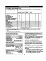
CUSTOMER RESPONSIBILITIES
MAINTENANCE TASK
Cleaning System
CheckJclean water inlet screen
on quick-connect.
Ched,(high pressure ho6e.
Check detergent ho_e.
Check spray gunand assembly for leaks.
Purge pump of _drand contaminants.
ENGINE
Check oillevel.
Servicefoam _r.
Service paper air Citer.
Change engine oil.
Clean/repk_cespark plug.
Clean sparkarrestorscreen
Prepare for storage,
HOURLY OPERATING INTERVAL
xt
x
x
x
x
x
Every 25
HOUPI 0€
Y_y
x-
Eve W 50 Every 100
Hours or Hours or
yearly Yeady
X"
X"
X
X
Prepare unitfor storage if if is to remain
idle for longer than 30 days.
SERVICE DATES
C_eanifclogged. Replace if perforated ortom.
Changeoil after thefirst (8) operating hoursand every 50 hours thereafter. Change sooner when eperaUng under dirty or dusty
condi_ns. ._
" Replace more of_n under dirty or dustycondiUons.
PRODUCT SPECIFICATIONS In the State of Caiifomia a spark arrestor is required
by law (Section 4442 ofthe CaliforniaPublic
Resources Code). Other states may have similarlaws.
Federal laws apply onfederal lands.
Note: Ifyou equip theengine of yourcleaningsystem
with a spark arrestor muffler,the spark arrestormust
be maintainedin effectiveworkingorder bythe
owner/operator.
Cleaning System Specifications
)RESSURE
FLOW RATE
CHEMICAL MIX
WATER SUPPLY
TEMPERATURE
3000 Psi
2.5 GPM
Use as directed
Not to Exceed 140°F
Engine Specifications
ENGINE MODEL GN-220
RATED HORSEPOWER 7.8
SPARK PLUG: Type: Champion RC12YC
or equivalent. Set
Gap to: 0.030 inch
(0.76mm)
GASOLINE CAPACITY 1 Gallon
OIL SAE 30 weiaht
SOLID STATE 0.0125 inch
IGNITION AIR GAP
GENERAL RECOMMENDATIONS
The warrantyof the cleaningsystem does notcover
items that have been subjectedto operatorabuse or
negligence. To receivefull value from the warranty,
operator must maintaincleaningsystem as instructed
in this manual.
Some adjustmentswillneed to be made periodicallyto
propedymaintain yourcleaningsystem.
All adjustments in theService and Adjustments
section ofthis manualshouldbe made at leastonce
each season.
• Once a year you shouldclean or replacethe spark
plug and replace theair filterand checkthegun
and wand assemblyfor wear. A clean sparkplug
and new air filter assure properfuel-air mixtureand
helpyour engine runbetter and lastlonger.
10

BEFOREEACHUSE
Checkwaterinletscreenfordamage.
• Checkhighpressurehoseforleaks.
Checkchemicaltanksandfillersfor damage.
• Check gun and wand assemblyfor leaks.
• Purge pumpofair and contaminants.
• Check engine oil level.
CLEANING SYSTEM MAINTENANCE
Check and Clean Inlet Screen
Examine garden hose inletscreen. Clean if if is
cloggedor replaceifit istom.
Check High Pressure Hose
High pressure hosescan develop leaksfrom wear,
kinking,or abuse, inspecthose beforeeach use.
Check for cuts, leaks, abrasions, bulgingof cover, or
damage or movement ofcouplings, ffany of these
conditionsexist, replace hose immediately.
A DANGER: Never repair a highpressure hose.
Replace with hosethat meetsthe minimum
pressurerating ofyour cleaningsystem
Check Chemical Reservoirs
Tank coversshouldsnap cleanlyontotank. Ensure
chemicallabelscorrectlyidentifytank contents.
Ensurethat the System Rinsetank isfilled with clean
water. Ensurethat Dial-A-CleanerTM selectorknob
rotatesfreely between each position.Examine the
tanks and replaceifthe filter is clogged
Check Gun and Wand
Examine:h0seconnectionto gun and make sure itis
secure.Test triggerby pressingif and making sure it
springsback intoplace when you release it. Put safety
latch in UP positionand test trigger.You should not be
able topress trigger.Replace gun immediatelyif it
fails any ofthese tests.
Purge Pump of Air and Contaminants
To removethe air from the pump, followthese steps:
• Set up the cleaningsystem as described in the
ASSEMBLY sectionand connect the water supply.
• Remove thewand extensionfromthe gun.
• Pullthetriggeron the gun and holduntil a steady
streamofwater appears.
To removethe contaminants from the pump, follow
these steps:
• Set upthe cleaningsystem as describedin the
ASSEMBLY section,and connect the water supply.
• Remove the nozzleattachmentfrom the gun.
Startthe engine according to instructionsin
OPERATION section.
• Pullthe triggeron the gunand hold.
• When thewater supplyis steadyand constant,
engage the safetylatch and refsstenthe nozzle
attachment.
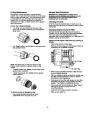
Nozzle Maintenance
If the nozzlebecomes restrictedor cloggedwith
foreignmaterials,suchas dirt,excessivepump
pressure may develop.A partiallycloggednozzlecan
cause a pulsingconditionduring use.This generallyis
not a pumprelatedproblem,but rathera clogged or
partiallyrsstdctednozzle.
If the nozzle becomescloggedor partiallyrestricted,
immediatelycleanthe nozzlewiththe kitincludedwith
yourcleaningsystem byfollowingthese instructions:
• Shut offtheengine and tam offthe water supply.
Presstriggerto relivewater pressure.
• Separate the dual lancefrom the gun.
• Usethe wire includedin the kitor a small paper
cliptofree the foreign materialscloggingor
restrictingthe nozzle.
Insert wire Into
nozzle and tum
back and forth
to clear
obstruction.
Remove additionaldebrisby backflushingwater
supplythroughdual lance (Figure2). Back flush
between 30 to 60 seconds.Backflushbothlances
bytumingchemicalvalve handle.
• Reconnectthe dual lanceto the spraygun.
• Reconnectthe water supply,turnon thewater, and
startthe engine.
• Test thecleaningsystem byoperatingwith the unit
in highand the low pressure.
11

O-Ring Maintenance
Throughthe normaloperation of yourcleaning
system,the o-ringskeep the connectionsof the hoses
and guntightand leak-free. They may becomeworn
or damagedwith use. Providedwith yourcleaning
system isan o-ring Maintenance Kit containing
replacemento-rings, a rubberwasher and a garden
hose inletscreen.
Partsin the O-Ring Kit Include:
• 1 O-Ring, red, (p/n B2726) for the end ofthe
spray gun connectionbetween gunand high/low
spray wand.
• 2 O-Rings, yellow, (p/n B2264) forthe ends ofthe
highpressure hose.
Note: The above two o-rings are closein size.
Please matchcarefully to assure propero-ring
usage.
• 1 rubber washer (p/n B2385) for the insideofthe
garden hose connector.
• 1 water inletscreen (p/n B2384) for the garden
hose connector.
Toramowawomordamegedo-ring:
• Use a small flathead screwdriverto get
underneaththe o-ring and pp/it off.
ENGINE MAINTENANCE
Maintenance, replacement or repair of the
emission control devices and systems may be
performed by any non-road engine repair
establishment or individual.
Checking Oil Level
oil level shouldbe chockedpriorto each use orat
least everyeight(8) hoursof operation.Keep oil level
maintained.
Changing Engine Oil and Oil Rlter
Change oilafterfirsteight(8) hoursofoperation.
Change oil& oilfiltereveryfifty (50) hoursthereafter.
Ifyou are usingyourcleaningsystemunder
extremelydirtyor dustyconditions, or in extremely hot
weather, changeoilmore often.
Change oilwhileengine issUUwaan from nmning,ee
follows:
Clean area aroundoil drain plug.
Remove oildrainplug and oilfillplugand drain oil
completely intoa suitable container.
n Rug
• When oilhascompletelydrained,Installoildrain
plugand tighten securely.
• Place a suitablecontainerbeneath the oilfilterand
tumfiltercountemlockwiseto remove.Discard
accordingto localregulations.
• Coat gasketof newfilter with engineoil.turnfilter
clockwiseuntilgasketcontacts tightlywith filter
adapter. Thentightenan additional3/4 turn.
• Fill oilsumpwith recommendedoil. (See =Before
Startingthe Engine"on page 8 for oil
recommendations)
• Installthe oilfill plugand tightensecurely.
• Wipe up any spilledoil.
12

ServiceAir Cleaner
Yourenginewillnotrunproperlyandmaybe
damagedffyourunitusingadirtyaircleaner.Clean
orreplacetheaircleanerpaperfilleronceevery50
hoursofoperationoronceayear,whichevercomes
first. Clean or replace more oftenif operatingunder
dusty or dirtyconditions.Cleanfoam pre-tiller every
25 hours ofoperation or sooner underdusty
conditions.
To clean or replacetheair cleanercomponents:
• Loosen the two screwson the air cleanercover.
Remove the air cleaner cover.
Foam
Pra-Filter May
Stick to Cover
Remove the paper air filler and thefoam pre-filler
from the air cleaner cover.
FO/_ll
Pre-FIIter
/
Paper
Filter
• To clean or replace foam pre-filter:
A. Wash pre-filter in soapywater.
B. Squeeze pre-filterdry inclean cloth. Do not
twist. If the pre-filler isstilldirtyafter washing
and drying it, replace itwitha new one.
Note: If you need to order a new air filter,please
call 1-800-366-PART.
C. Apply enough engine oilto saturatethe
pre-filter.
D. Wrap the pre-filler in a clean dry clothand
squeeze outthe excess oil. Do not twist. Set
the pre-filter aside.
To clean or replace paper air filter:
A. Clean paper filler bytappingit gentlyon a
solidsurface.If the filler istoo dirty, replaceit
with a new one. Dispose ofthe oldfilter
properly.
Clean air cleanercover.
Insert pre-filler intothe cover, then the paper air
filler.
Reinstallthe air cleanercover and tightenthe two
(2) screws.
CleanSparkArrestorScreen
The engine exhaustmuffler has a sparkarrestor
screen. Inspectand clean the screen every 100 hours
ofoperation or onceeach year, whichevercomes first.
Note: If you use yourcleaning systemon any forest-
covered, brush-coveredor grass-coveredunimproved
land, itmusthave a spark arrestor. The spark arrestor
mustbe maintainedin good condition bythe
owner/operator.
Clsenand inspectthe sparkattester as follows:
Inspectthe screen and replace itif itistom, perforated
or otherwisedamaged. Do not use a defective ,
screen. Ifthe screen is not damaged, clean itwith'a
chemicalsolvent.
Ifthe spark arrestor isdamaged, replace itas follows:
• Remove the four (4) screwsthat connect the heat
shield tothe muffler.
• Remove four.-(_4)screwsthat attach the spark
arrestorscreen.
• Replace damagedscreen with new screen (p/n
83083).
• Reattach the sparkarrestor screen and the heat
shield.
13

Clean/ Replace Spark Plug
Replacethe spark plugyearly or every100 hoursof
operation,whichevercomes first.
CAUTION: Disconnectsparkplugwire from
,_ spark plugand keep wire away spark plug.
from
Clean area aroundspark plug.
• Remove spark plugform the cylinderhead.
• Replacespark plugif the electrodesare pitted,
burnedor porcelainis cracked.For replacement
useChampion RC12YC or equivalent.
• Check electrodegap with wirefeeler gaugeand set
gap to0.76ram (.030 inches), if necessary.
• installa correctlygapped spark plugintothe
cylinderhead, tightensecure|y.
\
Carburetor
Ifyou thinkyourcarburetorneeds adjusting,see your
nearestSears Service Center. Engineperformance
may be affectedat altitudesabove 5000 feet. For
operationat higherelevations,contactyournearest
Sears ServiceCenter.
Adjusting Valve Clearance
Afterthe firstfilly (50) hoursofoperation,you should
adjust the valve clearancein the engine.
Important: If you feel uncomfortableaboutdoingthis
procedureor you don'thave the propertools,please
take yourcleaningsystem in tothe nearestservice
centerto have thevalve clearanceadjusted. This isa
very importantstepto insurethe longestlifeforyour
engine.
To adjustvalve clearance:
• Make sure the engine isat roomtemperature.
• Makesure that the spark plugwire isremovedfrom
the spark plugand outof the way.
• Removethe breathertube from the valvecover.
Removethe fours_rewsattaching thevalve cover
witha #2 or 3 phillipsscrewdriver.
O
Valve Cover Breather Tube
Make sure the piston isat Top Dead Cer_ter('rDC)
ofitscompressionstroke (bothvalves closed). To
getthe pistonat top dead center, pullon the recoil
handleslowlywatchingthe pistontroughthe spark
plughole. As you pull on the recoil handlethe ,
piston shouldmove up and down. The pistonisput
Top Dead Center when it is up as high as it can go.
Allen Wmnol
in-lb$
LooNn Jam Nut
* Using a 10mm wrench, loosen the rockerarmjam
nut. Use an 8ramallen wrenchto tum the pivotball
studwhile checkingclearance between the rocker
arm and the valve stern witha feeler gauge.
Correct clearance is 0.002-0.004 inch (0.05-
0.1mm). Note: You must holdthe rockerarmjam
n_ in place as you turn the pivotball stud.
, When valve clearance is correct, holdthe pivotball
stud inplace withthe allen wrenchand tightenthe
rockerarm jam nut. Tighten the jam nut to 65-85
inch-poundstorque.After tighteningthe jam nut,
recheckvalve clearance to make sure ff did not
change.
14

• Reattach the valve cover makingsure the gasket
between the valve cover and cylinderhead is in
place. Startall fourscrews beforetighteningor you
will not be able to get all thescrewsin place.
• Reattach the breather tube.
• Reattach the spark plug wire tothe spark plug.
Retorque Head Bolts
After the first50 hoursof operation,you mustretorque
the head boltsto 4.0 kg.-m. (22 ft.-Ibs.)
Important: If you feel uncomfortableaboutdoingthis
procedure or you don't have the propertools, please
take yourcleaning system in tothe nearestservice
center to havethe valve clearanceadjusted.This is a
very importantstepto insure the longestlifefor your
engine.
Note: Only performthis adjustmentafter first50 hours
of operation.The head bolts willneed no further
adjustment.
• Remove the four (4) screwsfrom the valvecover.
• Remove the valve cover and gasket.
• Torque the bolts to 4.0 kg-m (22 ft-lb).
• Torque sequence isas follows: A, B, C, D, E (star
pattern).
A
c
jE
15

AFTER EACH USE
Water shouldnot remain in the unitfor longperiods of
time. Sediments of minerals can deposit on pump
parts and "freeze" pumpaction. Follow these
procedures after every use:
• Flush the chemical system by selectingthe System
Rinse tank and run the cleaning system with nozzle
in low pressure mode. Flush for one minute or until
the chemical is cleared from the system.
• Shut off the engine and let it cool,then remove all
hoses.
,_ CAUTION: Be sure the engineRun/Stopswitch
is in the "Stop" positionbeforeyoucontinue.
• Emptythe pump ofall pumpedliquidsbypulling
recoilhandleabout6 times withthe Run/Stop
switchin the "Stop" position.Thisshouldremove
mostof the liquidin the pump.
• Rotate the Dial-A-CleanerTM selectorknobto the
OFF position.
• Coilthe highpressurehose and inspectit for
damage. Cuts in the hose or frayingcouldresultin
leaks and loss of pressure.Shouldanydamage be
found, replacethe hose. DO NOT attemptto repair
a damaged hose. Replacethe hosewiththe
genuineCraftsmanpart.
Drain waterfrom hose and properlyhangiton the
wire supportprovided.
• Store system in a clean, dry area.
A
DANGER: Never storethe enginewithfuel in
the gastank indoorsor inenclosed,poorly
ventilatedareas where fumesmay reach an
openflame, a spark,or pilotlight.
WINTER STORAGE
,_ CAUTION: You mustprotectyourunitfrom
freezingtemperatures.Failure to do sowill
permanentlydamage your pumpand render
yourunitinoperable.
To protectthe unitfrom freez_ tempaatums:
• Empty all chemicalreservoirsas follows:
a. Disconnecthose connectedto chemicalinject
fittingon the pump. Place end of hose into
suitablecontainer.
b. Move the selectorknobto Tank A and open
that tank's cover.Gravity shouldshortlyempty
the tank contentsintothecontainer.
c. When the tank isempty, repeatstep (b)for
tanks B and C.
d. Reconnectthe hoseto the chemicalinject
fitting on the pump. Add0.5 literof cleanfresh
water to eachtank and closetank'scovers.
• Flushthe chemicalsystem by selecting a tank and
run the cleaningsystem with nozzle in low pressure
mode. Flush untileach tank isempty, then switch
the selector knobtothe nexttank. The lasttankto
be emptied mustbe the System Rinsetank.
• Connect a 3-foot sectionof garden hoseto the inlet
adapter. Pour RV-Antifreeze (antifreeze without
alcohol)intothe hose. Pullthe recoil handletwice.
LONG TERM STORAGE
Ifyou do notplan to use the cleaning systemfor more
than 30 days, you mustprepare the engine for long
term storage.
It isimportantto preventgum depositsfrom formingin
essentialfuel system parts such as the carb_Jretor,fuel
filter,fuel hose or tank dudngstorage. Also,
experienceindicatesthat alcohol-blendedfu_ls (celled
gasohol,ethanol or methanol) can attract moisture
whichleads to separationand formation of acids
duringstorage. Acidicgas can damage the fuel system
of an engine while instorage.
p
Protect Fuel System
,_ DANGER: Drainfuel intoapproved container
outdoors,away from openflame. Be sure
engine is cool. Do not smoke.
Remove all ga,sqlinefrom thefuel tank toprevent
gum deposits from forming on these parts and
causingpossible malfunctionofengine.
Run engine unUIengine stops from lack offuel.
Make sure you have water supply to pumpinlet
connectedand turnedON.
Change Oil
While engine is stillwarm, drain oilfrom crankcase.
Refillwith recommendedgrade. (See ChangingOil)
Oil Cylinder Bore
• Remove spark plug.Squid about I ounce (30 ml)of
engineoil intothecylinder. Cover spark plug hole
with rag. Crank engine slowlyto distributeoil.
_k CAUTION: Avoidspray from spark plughole
when crankingengine.
• Installspark plug. Do not connect sparkplug wire.
OTHER
• Do notstore gasolinefrom one season toanother.
• Ifpossible, store yourunitindoorsand cover itto
give protectionfrom dust and dirt. BE SURE TO
EMPTY THE FUEL TANK.
IMPORTANT: NEVER cover yourcleaningsystem
whileengine and exhaustarea are warm.
16

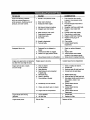
1.
PROBLEM
Pump has followingproblems:
failureto producepressure,or
erraticpressure, chattering,loss of
pressure, lowwater volume.
Detergent fails to mix.
CAUSE
Nozzlein lowpressuremode.
2. Water inlet isblocked.
3. Inadequate water supply
4.
5.
6.
7.
8.
9.
10. Nozzle is obstructed.
11. Pump is faulty.
1. Detergent line is collapsed or
kinked
2. Chemical tank filter is clogged.
3. Nozzle is in highpressure mode.
t.
2.
3.
4.
inlet hose is kinked or leaking
Clogged water inletscreen. 5.
Water supplyis over 140°F. 6.
Outlet hose is blocked. 7.
Outlet hose leaks. 8.
Gun leaks. 9.
10.
11.
1.
Engine runs good when not spraying
but dies when you beginto spray.
Engine_'ill net start;or starts 1.
and runs rough 2.
3.
4.
5.
6.
7.
CORRECTION
Twistchemical valve handle
to place in low pressuremode.
Clear inlet
Provideadequate water flowat
least 3 gem.
Straighteninlethose, patch leak.
Replace / cleanwater inlet
screen.
Provide coolerwater supply.
Clear blocksin outlethose.
Replace outlethose ifleaking.
Replace O-ring orgun if
necsssaq/.
Clear nozzle.
ContactSears Service
Department.
4. Dial-a-Cleaner knob isin off position.
Enginespeed is too slow. ContactSears Service Department.
Dirtyair cleaner
Out ofgasoline.
Stele gasoline.
Spark plug wire not connected
tospark plug.
Bad spark plug.
Water in gasoline.
Ovemhokingor flooded
8. Excessivelyrichfuel mixture.
9. Intake valve stuckopen or closed.
10. Engine has lostcompression.
Engine shuts downduring 1. Out of gasoline.
operation 2. Airfilter dirty
Enginelacks power. Dirtyairfilter. Replace airfilter.
Repair or replace detergent
line.
2. Replacetank
3. Twist chemical valve handle
to place in low pressuremode.
4. Rotate knobfor desired chemical.
1. Clean or replace air cleaner.
2. Fill fuel tank.
3. Drain gas tank; fillwith freshfuel.
4, Connectwire to spark plug.
5. Replace spark plug.
6. Drain gastank; fill with freshfuel.
7. Set engine throttlecontrolleverto
fast position,choke in mn
position.
8. Contact Sears Service
Department.
9. ContactSears Service
Department.
10. ContactSears Service
Department.
1. Fillfuel tank.
2. Replace Air filter.
17

18

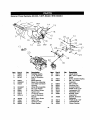
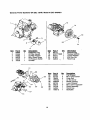
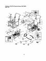
Generac Power Systems GN 220, 7.8HP, Model # EHC 04048-0
8
9
I0
17
5
14
12 ou_K GR_. 2 1
2O
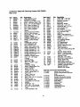
Item B_c!__ Otv
7 78653 1
8 85272 1
9 84195 1
10 85620
11 00285271
12 84329
13 00185271
14 22097
15 82981
16 81675
17 84274
18 87221A
1
1
1
1
2
2
1
1
1
1
1
1
1
19 45756
20 72347
21 86962
22 85953
22
6
"A" _523
37-_!
I
29
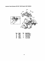
Run/Stop Switch 23 A9311 1
L.E.D. Assembly 24 83512 1
Low Oil Shutdown
Decal 25 78604 1
Black Sleeving 26 89230 1
BlackWire Assembly
3-pin Male Connector 27 83503
Housing 29 86384
White Wire Assembly 30 86037
M6 Lock Washer 31 36701
M6 x 30mm Screw 32 22152
IgnitionCoil 33 23897
Tinnerman Clamp 34 A9567
Low Oil Shutdown
Module 35 A9568 1
M6 x 10ram Screw
Spark Plug 36 36919 1
Governor Lever 37 22264 1
Wear Washer 38 A9943 1
31
27
24
AdjustScrew
M8 x 15mmTaptite
Screw
60 Hz. GovernorSpring
M8-1.25 x 35mm
Capscrew
M5 Lock Nut
GovernorRod
Anti-lashSpring
PHMS 10-32 x 1/2"
Lockwasher,#10
Flatwasher,#10
Bracket,Pivot/
Adjustment
Bracket,Governor
Weldment
PHMS 8--32 x 5/8"
Lockwasher#8
Clamp, Bowden
19

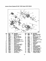
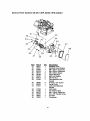
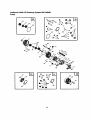
Generac Power Systems GN 220, 7.8HP, Model # EHC 04048-0
36
7
28
46
17
33
1 78621 1
2 76389 1
3 88411 1
4 A8897A 1
5 77168 5
6 88057 1
7 76390 2
8 83337A 1
9 78658 1
10 78659 1
11 89213J 1
12 A7637 1
13 81695 2
14 A8929 1
15 78645 1
16 A7811 1
17 72683 1
18 98752 1
19 89096 1
20 88156 1
21 A8822 1
22 78691 1
23 A57-/2 1
24 A5776 1
25 74908 1
18
!_ aem _ c_v
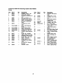
Control RodAssembly 26 78606 4
PistonPin 27 76361 1
Piston RingSet
Gear Cover Assembly 28 89230 6
M8 x 52ram Head Bolt 29 99922 1
Piston 30 A1720 2
Pin Retainer Ring 31 88401 2
Tapered CrankshaftAssm. 32 84186 2
Governor=R"Pin 33 83192 1
GovernorArm Thrust Washer 34 86254 1
CrankcaseAssm. 36 21705B 1
GovernorArm 37 90082 1
Oil Seal 38 90081 1
Govemor Gear Assembly 39 88396A 2
GovernorGear .C-Ring 40 83235 2
GovemorSpool 41 80336 1
1/8" NPT Pipe Plug 42 96362 1
CamshaftAssembly 43 77161 2
CrankcaseGasket 44 77160 2
Valve Stem Seal 45 76307 2
CylinderHead Gasket 46 88403 1
Oil PressureReliefCover 47 72657 2
Oil PressureSpring 48 88412 1
11/32" Ball 49 76329 1
M5 Form Screw 50 21944E
Lo_a
M6-1.Ox 12mm Screw
Govemor Gear Thrust
Washer
M8-1.25 x 35mm Screw
SpringWasher
Valve SpringRetainer
Valve Spring
Valve SpringWear Washer
GeroterSet
=O" Ring
CylinderHead Assembly
ExhaustValve
Intake Valve
Push Rod
Tappet
Oil Pick-upAssembly
Rocker CoverGasket
Pivot BallStud
GN-190/220 RockerArm
Rocker ArmJam Nut
Push Rod GuidePlate
1/4" NPT Pipe Plug
RockerCover Assembly
PlasticOil Fill Plug
Complete LongBlock
2O
Page is loading ...
Page is loading ...
Page is loading ...
Page is loading ...
Page is loading ...
Page is loading ...
Page is loading ...
Page is loading ...
Page is loading ...
Page is loading ...
-
 1
1
-
 2
2
-
 3
3
-
 4
4
-
 5
5
-
 6
6
-
 7
7
-
 8
8
-
 9
9
-
 10
10
-
 11
11
-
 12
12
-
 13
13
-
 14
14
-
 15
15
-
 16
16
-
 17
17
-
 18
18
-
 19
19
-
 20
20
-
 21
21
-
 22
22
-
 23
23
-
 24
24
-
 25
25
-
 26
26
-
 27
27
-
 28
28
-
 29
29
-
 30
30


Craftsman 580.768050 User manual
- Category
- High-pressure cleaners
- Type
- User manual
- This manual is also suitable for
Ask a question and I''ll find the answer in the document
Finding information in a document is now easier with AI
Related papers
-
Craftsman 580.768050 Operating instructions
-
-
-
-
-
-
-
-
-
Sears 580.761652 User manual
Other documents
-
 ATD Tools ATD-3736 User manual
-
Generac Power Systems GH-410 Owner's manual
-
Simplicity 00606-0 User manual
-
Protocol 1352 Flat Screen TV Cleaner User manual
-
-
Generac 190/220 User manual
-
-
-
SKEY Expandable Garden Hose User manual
-
