Hearth and Home Technologies CFL-18LP-C Owner's manual

Category
Fireplaces
Type
Owner's manual
1Hearth & Home Technologies • CFL-18/24/30-C, CFL-24-IPI, ST-CFL-24-B • 526-910 Rev. L • 11/14
MODELS:
NATURAL GAS PROPANE
CFL-18NG-C CFL-18LP-C
CFL-24NG-C CFL-24LP-C
CFL-30NG-C CFL-30LP-C
ST-CFL-24NG-B ST-CFL-24LP-B
CFL-24NG-IPI CFL-24LP-IPI
Do not store or use gasoline or other am-
mable vapors and liquids in the vicinity of
this or any other appliance.
What to do if you smell gas
- Do not try to light any appliance.
- Do not touch any electrical switch. Do not
use any phone in your building.
- Immediately call your gas supplier from a
neighbor’s phone. Follow the gas suppli-
er’s instructions.
- If you cannot reach your gas supplier, call
the re department.
Installation and service must be performed
by a quali ed installer, service agency, or the
gas supplier.
WARNING: If the information in these
instructions is not followed exactly, a re
or explosion may result causing property
damage, personal injury, or death.
Owners Manual
Installation and Operation
DO NOT DISCARD THIS MANUAL
CAUTION
Installation and service of this appliance should be
performed by quali ed personnel. Hearth & Home
Technologies suggests NFI certi ed or factory trained
professionals, or technicians supervised by an NFI
certi ed professional.
Leave this manual with
party responsible for use
and operation.
DO NOT
DISCARD
• Important operating
and maintenance
instructions included.
Read, understand and follow
these instructions for safe
installation and operation.
In the Commonwealth of Massachusetts:
Installation must be performed by a licensed plumber
or gas tter.
• The chimney ue damper, when used with gas logs,
will be welded open or completely removed.
A CO detector shall be installed in the room where the
appliance is installed.
WARNING
This appliance has been supplied with an integral barrier
to prevent direct contact with the xed glass panel. DO
NOT operate the appliance with the barrier removed.
Contact your dealer or Hearth & Home Technologies if the
barrier is not present or help is needed to properly install one.
HOT SURFACES!
Glass and other surfaces are hot during
operation AND cool down.
Hot glass will cause burns.
Do not touch glass until it is cooled
NEVER allow children to touch glass
Keep children away
CAREFULLY SUPERVISE children in same room as
replace.
Alert children and adults to hazards of high temperatures.
High temperatures may ignite clothing or other ammable
materials.
Keep clothing, furniture, draperies and other ammable
materials away.
Hearth & Home Technologies • CFL-18/24/30-C, CFL-24-IPI, ST-CFL-24-B • 526-910 Rev. L • 11/142
Congratulations
Listing Label Information/Location
Model Name: ___________________________________________ Date purchased/installed: __________________
Serial Number: __________________________________________ Location on appliance: ____________________
Dealership purchased from: _______________________________ Dealer Phone: __________________________
Notes: _______________________________________________________________________________________
_____________________________________________________________________________________________
Read this manual before installing or operating this appliance.
Please retain this owner’s manual for future reference.
We recommend that you record the following pertinent
information about your appliance.
Gas Information
Serial Number
Type of Gas
The model information regarding your speci c appliance can be found on
the rating plate usually located in the control area of the appliance.
Homeowner Reference Information
Model Number
for Not Not for use use with with solid solid fuel.fuel.
((Ne Ne doit doit pas pas entre entre utilise utilise avec avec un un combustible combustible solide).solide).
This This appliance appliance must must be be installed installed in in accordance accordance with with local local codes, codes, if if any; any; if if not, not, follow follow ANSI ANSI Z223.1Z223.1
in in the the USA USA or or CAN/CGA CAN/CGA B149 B149 installation installation codes. codes. (Installer (Installer l’appareil l’appareil selon selon les les codes codes ou ou reglementsreglements
locaux locaux ou, ou, en en l’absence l’absence de de tels tels reglements, reglements, selon selon les les codes codes d’installation d’installation CAN/CGA-B149.)CAN/CGA-B149.)
Type Type of of Gas Gas (Sorte (Sorte De De Gaz)Gaz)::
NNAATURALTURAL GASGAS
MADE MADE IN IN USAUSA
Minimum Minimum Permissible Permissible Gas Gas Supply Supply for for Purposes Purposes of of Input Input Adjustment.Adjustment.
Approved Approved Minimum Minimum (De (De Gaz) Gaz) AcceptableAcceptable 0.00.0 in in w.c.w.c. (Po. (Po. Col. Col. d’eau)d’eau)
Maximum Maximum Pressure Pressure (Pression)(Pression) 0.00.0 in in w.c.w.c. (Po. (Po. Col. Col. d’eau)d’eau)
Maximum Maximum Manifold Manifold Pressure Pressure (Pression)(Pression) 0.00.0 in in w.c.w.c. (Po. (Po. Col. Col. d’eau)d’eau)
Minimum Minimum Manifold Manifold Pressure Pressure (Pression)(Pression) 0.00.0 in in w.c.w.c. (Po. (Po. Col. Col. d’eau)d’eau)
Model:Model:
(Modele):(Modele):
SerialSerial
(Serie):(Serie):
ANSI ANSI Z21XX-XXXX Z21XX-XXXX · · CSA CSA 2.XX-MXX 2.XX-MXX · · UL307BUL307B
XXXXXXXXXXXXXXXX
IN IN CANADACANADA
ALTITUDE:ALTITUDE: 0-0000 0-0000 FT.FT. 0000-0000FT.0000-0000FT.
MAX. MAX. INPUT INPUT BTUH:BTUH: 00,00000,000 00,00000,000
MIN. MIN. INPUT INPUT BTUH:BTUH: 00,00000,000 00,00000,000
ORIFICE ORIFICE SIZE:SIZE: #XXXXX#XXXXX #XXXXX#XXXXX
XXXXXXXXXXXXXXXX
Total Total Electrical Electrical Requirements: Requirements: 000Vac, 000Vac, 00Hz., 00Hz., less less than than 00 00 AmperesAmperes
Heatilator, a brand of Hearth & Home Technologies
7571 215th Street West, Lakeville, MN 55044
Congratulations on selecting a Hearth & Home Technologies
gas replace, an elegant and clean alternative to wood
burning replaces. The gas replace you have selected
is designed to provide the utmost in safety, reliability, and
ef ciency.
As the owner of a new replace, you’ll want to read and
carefully follow all of the instructions contained in this
owners manual. Pay special attention to all cautions and
warnings.
This owners manual should be retained for future
reference. We suggest that you keep it with your other
important documents and product manuals.
The information contained in this owners manual, unless
noted otherwise, applies to all models and gas control
systems.
Your new Hearth & Home Technologies gas replace will
give you years of durable use and trouble-free enjoyment.
Welcome to the Hearth & Home Technologies family of
replace products!
3Hearth & Home Technologies • CFL-18/24/30-C, CFL-24-IPI, ST-CFL-24-B • 526-910 Rev. L • 11/14
= Contains updated information.
Table of Contents
1 Introduction
A. Appliance Certi cation . . . . . . . . . . . . . . . . . . . . . . . . . . . . 4
B. BTU Speci cations . . . . . . . . . . . . . . . . . . . . . . . . . . . . . . . 6
C. High Altitude Installation . . . . . . . . . . . . . . . . . . . . . . . . . . . 6
2 Getting Started
A. Inspect Appliance and Components . . . . . . . . . . . . . . . . . . 7
B. Installation . . . . . . . . . . . . . . . . . . . . . . . . . . . . . . . . . . . . . 7
3 Operating Guidelines and Maintenance Instructions
A. Before Lighting Appliance. . . . . . . . . . . . . . . . . . . . . . . . . 10
B. Maintenance . . . . . . . . . . . . . . . . . . . . . . . . . . . . . . . . . . . 10
4 Troubleshooting
A. Standing Pilot Ignition System . . . . . . . . . . . . . . . . . . . . . 13
B. IntelliFire Ignition System . . . . . . . . . . . . . . . . . . . . . . . . . 15
5 Reference Materials
A. Service Parts . . . . . . . . . . . . . . . . . . . . . . . . . . . . . . . . . . 17
B. Limited Lifetime Warranty . . . . . . . . . . . . . . . . . . . . . . . . . 23
C. Contact Information . . . . . . . . . . . . . . . . . . . . . . . . . . . . . 25
Hearth & Home Technologies • CFL-18/24/30-C, CFL-24-IPI, ST-CFL-24-B • 526-910 Rev. L • 11/144
This log set is to be installed only in a solid-fuel burning
replace with a working ue and one constructed of non-
combustible material. The minimum permanent vent open-
ing provided by the replace chimney damper to vent the
ue products must not be less than 51 square inches (328
cm
2
). The chimney damper MUST be xed in a manner to
maintain the minimum permanent vent opening. This may
be accomplished by fastening the damper stop clamp pro-
vided to the edge of the damper to prevent its closing.
The installation, including provisions for combustion and
ventilation air, must conform with the National Fuel Gas
Code ANSI Z223.1 (in the United States), the CAN/CGA
B-149 Installation Code (in Canada) and applicable local
building codes.
These models can be installed in a bedroom (in the United
States) which has a total volume of uncon ned space ap-
propriate to the particular installation. Refer to the National
Fuel Gas Code ANSI Z223.1/NFPA 54-(current edition).
The Uniform Mechanical Code (current edition), and Local
Building Of cials for the options allowed in obtaining an
effective bedroom volume of uncon ned space.
Always keep the appliance area clear and free from com-
bustible materials, gasoline, and other ammable vapors
and liquids.
WARNING! Risk of Fire, Explosion or Electric Shock!
DO NOT use this appliance if any part has been under
water. Call a quali ed service technician to inspect the
appliance and to replace any part of the control system
and/or gas control which has been under water.
A. Appliance Certi cation
WARNING
Fire Risk
Asphyxiation Risk
These gas log sets have been tested and listed in the U.S.
in accordance with ANSI Z21.60b-2004. They have been
listed by Underwriters Laboratories Inc. for installation and
operation in the United States and Canada as described in
these Installation and Operation Instructions. All compo-
nents are UL, AGA, CGA or CSA safety certi ed.
Check with your local building code agency prior to install-
ing this appliance to ensure compliance with local codes,
including the need for permits and follow-up inspections. In
the absence of local codes, comply with the National Fuel
Gas Code, ANSI Z223.1-Latest Edition in the U.S. If any
assistance is required during installation, please contact
your local dealer.
CAUTION
Check the construction of the replace before installing the
gas log set. The area of the ue should not be less than 1/11
the area of the replace opening. Non-airtight glass doors
should be installed on the replace if the area of the ue
is less than 1/11 the area of the replace opening. Airtight
doors must never be used with this gas log set.
Fire Risk
THIS UNIT IS NOT FOR USE WITH SOLID
FUEL. Solid fuels shall not be burned in a
fireplace where a decorative appliance is
installed. Failure to follow these instructions
will result in a re.
WARNING
1
1
Introduction
Gas Log Sets are Decorative Gas Appliances for Installa-
tion in a Solid-fuel Burning Fireplace. Minimum replace
sizes for these models is shown in Figure 1.
MODELS: CFL-18NG/LP-C, CFL-24NG/LP-C, CFL-
30NG/LP-C, CFL-24NG/LP-IPI and ST-CFL-24NG/LP-B
LABORATORY: Underwriters Laboratories, Inc. (UL)
TYPE: Decorative Gas Appliances for Installation in
Solid-Fuel Burning Fireplaces
STANDARD: ANSI Z21.60b-2004 CSA 2.26b-2004
This log set must NOT be installed in an unvented
appliance.
Open the chimney damper to its fully open position when
burning this gas log set.
Logs must never be burned without the ue damper in the
full open position. Failure to do so is dangerous to your
health and voids all warranties.
All gas appliances produce some carbon monoxide when
operated. Carbon monoxide is a colorless, odorless,
poisonous gas. Adequate provisions must be made to
provide combustion air for this gas log set. If outside air is
not accessed by the replace, it may be necessary that an
additional combustion air source be provided.
5Hearth & Home Technologies • CFL-18/24/30-C, CFL-24-IPI, ST-CFL-24-B • 526-910 Rev. L • 11/14
MODEL CFL-18-C
MINIMUM FIREPLACE SIZE
FRONT WIDTH : 23 1/2” (750mm)
REAR WIDTH : 19
1/2” (521mm)
DEPTH : 13 1/2” (331mm)
HEIGHT : 22” (508mm)
23 1/2
MODEL CFL-24-C
TOP VIEW
MINIMUM FIREPLACE SIZE
FRONT WIDTH : 27 1/2” (750mm)
REAR WIDTH : 22” (521mm)
DEPTH : 15 1/2” (331mm)
HEIGHT : 22” (508mm)
15 1/2
27 1/2
22
TOP VIEW
13 1/2
19 1/2
TOP VIEW
MINIMUM FIREPLACE SIZE
FRONT WIDTH : 30” (750mm)
REAR WIDTH : 24” (521mm)
DEPTH : 15 1/2” (331mm)
HEIGHT : 22” (508mm)
15 1/2
30
24
MODEL CFL-30-C
MODEL ST-CFL-24-B
TOP VIEW
MINIMUM FIREPLACE SIZE
FRONT WIDTH : 24” (521mm)
REAR WIDTH : 24” (521mm)
DEPTH : 17” (331mm)
HEIGHT : 20” (508mm)
17
24
24
Figure 1. Minimum Fireplace Sizes for CFL-18/24/30-C and ST-CFL-24-B
Hearth & Home Technologies • CFL-18/24/30-C, CFL-24-IPI, ST-CFL-24-B • 526-910 Rev. L • 11/146
C. High Altitude Installation
NOTICE: If the heating value of the gas has been reduced,
these rules do not apply. Check with your local gas utility
or authorities having jurisdiction.
When installing above 2000 feet elevation:
In the USA: Reduce input rate 4% for each 1000 feet
above 2000 feet.
In CANADA: Reduce input rate 10% for elevations
between 2000 feet and 4500 feet. Above 4500 feet,
consult local gas utility.
Check with your local gas utility to determine proper ori ce
size.
B. BTU Speci cations
Models
(U.S. or Canada)
Input BTU/h
Ori ce
Size (DMS)
CFL-18NG-C
CFL-24NG-C
CFL-30NG-C
CFL-24NG-IPI
ST-CFL-24NG-B
(NG)
US
(0-2000 FT)
60,000 7-1.55 mm
CANADA
(2000-4500 FT)
54,000 #25 DMS
CFL-18LP-C
CFL-24LP-C
CFL-30LP-C
CFL-24LP-IPI
ST-CFL-24LP-C
(LP)
US
(0-2000 FT)
60,000 2.30 mm
CANADA
(2000-4500 FT)
54,000 #43 DMS
7Hearth & Home Technologies • CFL-18/24/30-C, CFL-24-IPI, ST-CFL-24-B • 526-910 Rev. L • 11/14
These models contain complete gas-burner, grate(s), and
log components needed. Use caution when handling logs
to avoid damage. Position the gas-burner assembly to the
rear of the replace. The ST-CFL-24 log set should be
positioned in the center of the unit. Once fully assembled,
the front log will extend forward of the burner assembly.
2
2
Getting Started
Note: The gas supply line should be purged of any trapped
air prior to the rst ring of the unit.
NOTICE: This installation must conform with local codes.
In the absence of local codes you must comply with the
National Fuel Gas Code, ANSI Z223.1-latest edition in
the U.S.A. and the CAN/CGA B149 Installation Codes in
Canada.
CAUTION! When installing this log set in a factory built
replace, be certain to consult the replace installation
manual. ALL knockouts in the replace through which the
gas supply line is run MUST be resealed with insulation
after the gas line is in place.
WARNING! Risk of Asphyxiation! Improper positioning
of log set may allow spillage and prohibit proper draft.
Position the log set as close to the back of the replace as
possible.
• Position ST-CFL log set in the center of the replace.
A. Inspect Appliance and Components
Carefully remove the appliance and components from
the packaging.
• If packaged separately, the log set and appliance grate
must be installed.
Report to your dealer any parts damaged in shipment,
particularly the condition of the glass.
Read all of the instructions before starting the instal-
lation. Follow these instructions carefully during the
installation to ensure maximum safety and bene t.
WARNING! Risk of Fire or Explosion! Damaged parts
could impair safe operation. DO NOT install damaged, in-
complete or substitute components. Keep appliance dry.
Hearth & Home Technologies disclaims any responsibility for,
and the warranty will be voided by, the following actions:
Installation and use of any damaged appliance or vent
system component.
• Modi cation of the appliance or vent system.
Installation other than as instructed by Hearth & Home
Technologies.
Improper positioning of the gas logs or the glass door.
Installation and/or use of any component part not approved
by Hearth & Home Technologies.
Any such action may cause a re hazard.
B. Installation
1. GAS CONNECTION
a. Run proper size gas line into replace. A 1/2 inch (13mm)
gas line, with a 3/8 inch (10mm) reduction for hook-up, is
usually suf cient for the Gas Log set; however, if the run
is unusually long, a larger line may be required. Contact
your local gas company or Department of Building and
Safety if there are any questions.
b. Optimum appliance performance requires proper input
pressures. Pressure requirements are:
Gas Pressure Natural Gas Propane
Minimum inlet pressure 5.0 in. w.c. 11.0 in. w.c.
Maximum inlet pressure 10.0 in. w.c. 13.0 in. w.c.
Manifold pressure 3.5 in. w.c. 10.0 in. w.c.
c. The appliance and its individual shut off valve must be
disconnected from the gas supply piping system during
any pressure testing of the system at test pressures in
excess of 1/2 psig.
d. This appliance must be isolated from the gas supply
piping system by closing its individual manual shut off
valve during any pressure testing of the gas supply
piping system at test pressures equal to or less than
1/2 psig.
WARNING! Risk of Fire or Explosion! High pressure
will damage valve. Low pressure may cause explosion.
Verify inlet pressures. Verify minimum pressures when
other household gas appliances are operating.
Install regulator upstream of valve if line pressure is
greater than 1/2 psig.
Hearth & Home Technologies • CFL-18/24/30-C, CFL-24-IPI, ST-CFL-24-B • 526-910 Rev. L • 11/148
Figure 1.
DAMPER CLAMP
OPEN DAMPER
WARNING! Risk of Fire!
Open the chimney damper to its FULLY OPEN posi-
tion when burning this gas log set.
DO NOT burn Logs without the ue damper in the
FULL OPEN position. Failure to do so is dangerous to
your health and voids all warranties.
Note: The Commonwealth of Massachusetts requires that
the chimney ue damper, when used with gas logs, shall be
welded open or completely removed.
Figure 2. IPI Wiring Diagram-CFL-24NG-IPI and CFL-24LP-IPI
2. ELECTRICAL INSTALLATION
This appliance may be used with a wall switch and/or
remote control.
Use low resistance thermostat wire for wiring from igni-
tion system to the wall switch.
Keep wire lengths as short as possible by removing any
excess wire length.
Low voltage and 110 VAC voltage cannot be shared
within the same wall box.
BLACK
RED
BATTERY PACK
(BATTERIES REQUIRED)
WIRES
(TO BROWN)
ORANGE
GREEN
VALVE
GROUND TO
FIREPLACE
CHASSIS
WHITE
ORANGE
IGNITION MODULE 3 VAC INTERMITTENT PILOT IGNITOR
I
S
REMOTE OR
WALL SWITCH
e. A damper stop clamp with set screw is provided to pre-
vent full closure of the replace damper blade. Attach
the clamp to the edge of the damper blade with pliers
or wrenches. If the damper stop supplied does not t
the application, use a permanent means that will keep
the damper open to a MINIMUM of 51 square inches
(328cm
2
). See Figure 1.
REMOTE
OR WALL
SWITCH
BLACK BLACK
ON/OFF
SWITCH
RED
THERMOPILE
WHITE
Figure 3. Standing Pilot Wiring Diagram
f. Test re the unit after referring to the SAFETY INFOR-
MATION and LIGHTING INSTRUCTIONS found in
Section 3 in this manual, or on the label plate assembly
found on the gas-burner.
g. After the gas line installation is complete, all connections
must be tightened and checked for leaks with a com-
mercially-available, non-corrosive leak check solution.
Be sure to rinse off all leak check solution following
testing. Refer to Section 3, OPERATING GUIDELINES
and MAINTENANCE INSTRUCTIONS.
h. Once the gas-burner is test red and gas supply lines
are purged, assemble the grate(s) and logs. Be certain
to follow the Log Placement Instructions shipped with
the unit. Remember to keep the Log Instructions along
with this manual for future use.
9Hearth & Home Technologies • CFL-18/24/30-C, CFL-24-IPI, ST-CFL-24-B • 526-910 Rev. L • 11/14
4. REMOTE CONTROL
If a remote control is used, the receiver cannot be placed
under the burner. If possible, place the receiver outside
the combustion chamber.
If the receiver must be placed in the combustion chamber,
the protective heat shield MUST be used. See Figure 4.
Position receiver on left side of gas log set (opposite the
pilot). Place protective heat shield over receiver. See
Figure 5.
Figure 4. Protective Heat Shield
Figure 5. Receiver Location-Left Side of Log Set
RECEIVER
RECEIVER
3. AIR SHUTTER SETTINGS.
This appliance has an adjustable air shutter (which con-
trols the primary air) factory set for the minimum vertical
vent run. If your installation has more than the minimum
required vertical vent length, adjustment of the air shutter
may be necessary to obtain optimal ame appearance.
This should be adjusted by a quali ed installer at the
time of installation.
Air Shutter Settings
NG LP
Burner 3/8 in. Full Open
Hearth & Home Technologies • CFL-18/24/30-C, CFL-24-IPI, ST-CFL-24-B • 526-910 Rev. L • 11/1410
3
3
Operating Guidelines and Maintenance Instructions
Fire Risk
Be sure replace screen or glass doors are in
place when burning replace logs. Unless other
provisions for combustion air are provided, the
screen or doors shall have an opening for intro-
duction of combustion air. THIS GAS LOG SET
IS NOT DESIGNED TO OPERATE WITH AIR
TIGHT GLASS DOORS. Adequate combustion
and cooling air must be provided or the unit will
not function properly.
WARNING
Fire Risk
Explosion Risk
WARNING: To avoid possible injury, re and
explosion, please read and follow these pre-
cautions and all instructions on this appliance
before lighting the pilot. Before lighting, smell
at oor level and/or use other means (such as
using a commercially-available, non-corrosive
leak check solution on all piping and connec-
tions, using a gas detector, etc.) to check for gas
leaks. NOTE: L.P. (Propane) gas can become
odorless and CANNOT always be detected
by smell.
WARNING
B. Maintenance
Periodically remove the logs and examine the burner. If
dirty, clean with a soft brush. Also examine the area around
the burner air shutter and the pilot. Any dirt or lint in this
area should be removed. This will ensure long life and
trouble-free operation.
The appliance and venting system should be inspected
before initial use and inspected and cleaned at least an-
nually by a quali ed eld service person.
A. Before Lighting Appliance
Before lighting this appliance determine if it has a Standing
Pilot or IntelliFire ignition system by viewing the wiring
system and gas valve. If this appliance has a red or black
ignitor button (see Figure 3 and Figure 4) this appliance
has a Standing Pilot ignition system. If there is no red or
black ignitor button, this appliance has an IntelliFire ignition
system.
Before operating this appliance have a quali ed tech-
nician:
• Remove all shipping materials.
Review proper placement of logs, rockwool, and ver-
miculite.
• Check the wiring.
• Ensure that there are no gas leaks.
Upon completing the gas line connection, a small amount
of air will be in the lines. When rst lighting the pilot light,
it will take a few minutes for the lines to purge themselves
of this air. Once the purging is complete, the pilot and
burner will light and operate as indicated in the instruc-
tion manual. Subsequent lighting of the appliance will not
require such purging.
WARNING
This appliance has been supplied with an integral barrier
to prevent direct contact with the xed glass panel. Do
NOT operate the appliance with the barrier removed.
Contact your dealer or Hearth & Home Technologies if the
barrier is not present or help is needed to properly install one.
HOT SURFACES!
Glass and other surfaces are hot during
operation AND cool down.
Hot glass will cause burns.
Do not touch glass until it is cooled
NEVER allow children to touch glass
Keep children away
CAREFULLY SUPERVISE children in same room as
replace.
Alert children and adults to hazards of high temperatures.
High temperatures may ignite clothing or other
ammable materials.
Keep clothing, furniture, draperies and other ammable
materials away.
WARNING! Risk of Fire, Explosion or Electric Shock!
DO NOT use this appliance if any part has been under
water. Call a quali ed service technician to inspect the
appliance and to replace any part of the control system
and/or gas control which has been under water.
Improper installation, adjustment, alteration, service or
maintenance can cause injury or property damage. For
assistance or additional information, consult a quali ed
service technician, service agency or your dealer.
11Hearth & Home Technologies • CFL-18/24/30-C, CFL-24-IPI, ST-CFL-24-B • 526-910 Rev. L • 11/14
Lighting Instructions (IPI)
The IPI system must be operated with two D-cell batteries.
1. This appliance is equipped with an ignition
device which automatically lights the burner.
DO NOT try to light the burner by hand.
2. Wait ve (5) minutes to clear out any gas.
Then smell for gas, including near the oor. If
you smell gas, STOP! Follow “B” in the Safety
Information located on the left side of this la-
bel. If you do not smell gas, go to next step.
3. To light the burner:
Equipped with wall switch: Turn ON/OFF switch
to ON.
Equipped with remote or wall control: Press
ON or FLAME button.
Equipped with thermostat: Set temperature to
desired setting.
4. If the appliance does not light after three tries,
call your service technician or gas supplier.
LIGHTING
INSTRUCTIONS (IPI)
TO TURN OFF
GAS TO APPLIANCE
1. Equipped with wall switch: Turn ON/OFF switch
to OFF.
Equipped with remote or wall control: Press
OFF button.
Equipped with thermostat: Set temperature to
lowest setting.
2. Service technician should turn off electric
power to the control when performing service.
FOR YOUR SAFETY
READ BEFORE LIGHTING
WARNING: If you do not follow these instructions exactly, a re or explosion
may result causing property damage, personal injury or loss of life.
CAUTION:
NOT FOR USE
WITH SOLID FUEL
WARNING:
GAS
VALVE
For additional information on operating your
Hearth & Home Technologies replace, please refer to www. replaces.com.
A. This appliance is equipped with an
intermittent pilot ignition (IPI) device
which automatically lights the burn-
er. DO NOT try to light the burner by
hand.
B. BEFORE LIGHTING, smell all around
the appliance area for gas. Be sure to
smell next to the oor because some
gas is heavier than air and will settle
on the oor.
WHAT TO DO IF YOU SMELL GAS
DO NOT try to light any appliance.
DO NOT touch any electric switch; do
not use any phone in your building.
DO NOT CONNECT LINE VOLT-
AGE (110/120 VAC OR 220/240
VAC) TO THE CONTROL VALVE.
Improper installation, adjustment, al-
teration, service or maintenance can
cause injury or property damage. Re-
fer to the owners information manual
provided with this appliance.
This appliance needs fresh air for
safe operation and must be installed
so there are provisions for adequate
combustion and ventilation air.
If not installed, operated, and main-
tained in accordance with the manufac-
turers instructions, this product could
expose you to substances in fuel or
fuel combustion which are known to the
State of California to cause cancer, birth
defects, or other reproductive harm.
Keep burner and control compartment
clean. See installation and operating
instructions accompanying appliance.
Hot while in operation. DO NOT touch.
Keep children, clothing, furniture, gaso-
line and other liquids having ammable
vapors away.
Immediately call your gas supplier
from a neighbors phone. Follow the
gas suppliers instructions.
If you cannot reach your gas sup-
plier, call the re department.
C. DO NOT use this appliance if any
part has been under water. Imme-
diately call a quali ed service tech-
nician to inspect the appliance and
to replace any part of the control
system and any gas control which
has been under water.
For use with natural gas and propane.
A conversion kit, as supplied by the
manufacturer, shall be used to convert
this appliance to the alternate fuel.
Also Certi ed for Installation in a
Bedroom or a Bedsitting Room.
For assistance or additional informa-
tion, consult a quali ed installer, ser-
vice agency or the gas supplier.
Final inspection by
Hearth & Home Technologies • CFL-18/24/30-C, CFL-24-IPI, ST-CFL-24-B • 526-910 Rev. L • 11/1412
1. Turn off all electric power to the appliance if
service is to be performed.
2. Open control access panel.
3. Move switch to “OFF” position.
4. Push in gas control knob slightly and turn clock-
wise to OFF”. Do not force.
5. Close control access panel.
5. Turn knob on gas control counter clockwise
to “PILOT”.
6. Push in control knob all the way and hold in. Im-
mediately depress red or black piezo button. It may
require several depressions of the red or black
piezo button until PILOT lights. If PILOT light does
not light after 10 seconds, return to step 3. Continue to
hold the control knob in for about one minute after the
pilot is lit. Release knob and it will pop back out. Pilot
should remain lit. If it goes out, repeat steps 3 through 6.
If knob does not pop up when released, stop and im-
mediately call your service technician or gas supplier.
If the pilot will not stay lit after several tries, turn
the gas control knob to “OFF” and call your service
technician or gas supplier.
7. Turn gas control knob counterclockwise to
“ON”.
8. To light Burner, ip the on/off switch to the “ON”
position, and close access grille.
9. Turn on all electric power to the appliance.
1. Turn off all electric power to the appliance.
2. Push in gas control knob
slightly and turn clockwise
to “OFF”.
NOTE: Knob cannot be turned from “PILOT” to “OFF”
unless knob is pushed in slightly. Do not force.
3. Wait ve (5) minutes to clear out any gas.
Then smell for gas, including near the oor. If
you smell gas, STOP! Follow “B” in the Safety
Information located on the left side of this label. If
you don’t smell gas, go to next step.
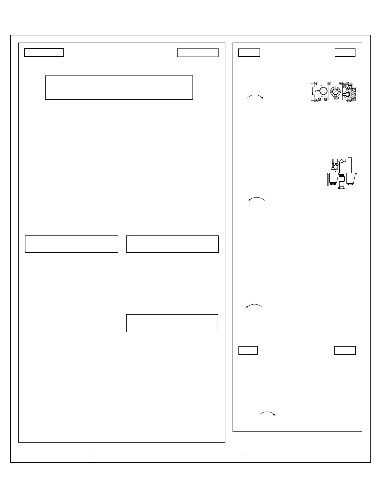
4. Find the pilot. The pilot is inside
combustion chamber next to the
main burner.
LIGHTING
INSTRUCTIONS
TO TURN OFF
GAS TO APPLIANCE
FOR YOUR SAFETY
READ BEFORE LIGHTING
DO NOT CONNECT 110 VAC TO
THE CONTROL VALVE.
Improper installation, adjustment, al-
teration, service or maintenance can
cause injury or property damage. Re-
fer to the owners information manual
provided with this appliance.
This appliance needs fresh air for
safe operation and must be installed
so there are provisions for adequate
combustion and ventilation air.
If not installed, operated, and main-
tained in accordance with the man-
ufacturers instructions, this product
could expose you to substances in fuel
or fuel combustion which are known to
the State of California to cause can-
cer, birth defects, or other reproduc-
tive harm.
Keep burner and control compartment
clean. See installation and operating
instructions accompanying appliance.
CAUTION:
Hot while in operation. Do not touch.
Keep children, clothing, furniture, gaso-
line and other liquids having ammable
vapors away.
NOT FOR USE
WITH SOLID FUEL
For use with natural gas and propane.
A conversion kit, as supplied by the
manufacturer, shall be used to convert
this appliance to the alternate fuel.
Also Certi ed for Installation in a
Bedroom or a Bedsitting Room.
For assistance or additional informa-
tion, consult a quali ed installer, ser-
vice agency or the gas supplier.
WARNING:
A. This appliance has a pilot which
must be lighted by hand. When
lighting the pilot, follow these in-
structions exactly.
B. BEFORE LIGHTING, smell all
around the appliance area for gas.
Be sure to smell next to the oor
because some gas is heavier than
air and will settle on the oor.
WHAT TO DO IF YOU SMELL GAS
Do not try to light any appliance.
Do not touch any electric switch; do
not use any phone in your building.
Immediately call your gas supplier
from a neighbors phone. Follow the
gas suppliers instructions.
If you cannot reach your gas sup-
plier, call the re department.
C. Use only your hand to push in or
turn the gas control knob. Never
use tools. If the knob will not push
in or turn by hand, DO NOT try to
repair it, call a quali ed service
technician. Force or attempted re-
pair may result in a re or explo-
sion.
D. Do not use this appliance if any
part has been under water. Imme-
diately call a quali ed service tech-
nician to inspect the appliance and
to replace any part of the control
system and any gas control which
has been under water.
For additional information on operating your
Hearth & Home Technologies replace, please refer to www. replaces.com.
WARNING: If you do not follow these instructions
exactly, a re or explosion may result causing property
damage, personal injury or loss of life.
Final inspection by
Figure 8. Standing Pilot Lighting Instructions
Lighting Instructions (Standing Pilot)
13Hearth & Home Technologies • CFL-18/24/30-C, CFL-24-IPI, ST-CFL-24-B • 526-910 Rev. L • 11/14
A. Standing Pilot Ignition System
4
4
Troubleshooting
With proper installation, operation, and maintenance your gas appliance will provide years of trouble-free service. If you do
experience a problem, this troubleshooting guide will assist a quali ed service technician in the diagnosis of a problem and
the corrective action to be taken. This troubleshooting guide can only be used by a quali ed service technician. Contact
your dealer to arrange a service call by a quali ed service technician.
Symptom Possible Causes Corrective Action
1. After repeated triggering
of the red or black piezo
ignitor button, the spark
ignitor will not light the
pilot.
A. No gas or low gas pressure. Check the remote shut-off valves from the appliance. Usually, there
is a valve near the gas main. There can be more than one valve
between the appliance and the main.
B. No lp in tank. Check the LP (propane) tank. You may be out of fuel.
C. Ignitor. Check the spark at the electrode and pilot. If no spark and electrode
wire is properly connected, replace the ignitor. Verify that there is no
short in electrode wire.
D. Pilot or misaligned electrode
(spark at electrode).
Using match, light the pilot. If the pilot lights, turn off the pilot and
trigger the piezo ignitor button again. If the pilot lights, an improper
gas/air mixture caused the bad lighting and a longer purge period is
recommended. If the pilot will not light, ensure the gap at the elec-
trode and pilot is one-eighth in. to have a strong spark. If the gap is
OK, replace the pilot.
2. The pilot will not stay lit
after carefully following
the lighting instructions.
A. Thermocouple. Check that the pilot ame impinges on the thermocouple. Adjust the
pilot for proper ame impingement.
Ensure that the thermocouple connection at the gas valve is fully
inserted and tight (hand tighten plus 1/4 turn).
Verify proper voltage output from the thermocouple to the valve.
Place one millivolt meter lead wire on the thermocouple copper lead.
Place the second lead wire on the solder button on the back of the
valve (blue wire). Start the pilot and hold the valve knob in. The
millivolt reading should read 8-16 millivolts. If millivolt reading is
less than 8 millivolts, replace thermocouple.
B. Improper gas inlet pressure. Natural gas should be 5-10 in. w.c. LP should be 11-13 in. w.c.
Verify pressure with manometer.
C. Valve. If the thermocouple is producing 8-16 millivolts, replace control valve.
3. The pilot is burning,
there is no burner
ame, the valve knob is
in the ON position, and
the ON/OFF switch is in
the ON position.
A. On/off switch or wires. Check the ON/OFF switch and wires for proper connections. Place
the jumper wires across the terminals at the switch. If the burner
comes on, replace the switch. If the switch is OK, place the jumper
wires across the switch wires at the gas valve. If the burner comes
on, the wires are faulty or connections are bad.
B. Thermopile may not be gen-
erating suf cient millivoltage.
Check that the pilot ame impinges thermopile properly.
Be sure the wire connections from the thermopile at the gas valve
terminals are tight and that the thermopile is fully inserted into the
pilot bracket.
Check the thermopile with a millivolt meter. Take the reading at
TH-TP&TP terminals of the gas valve. The meter should read 350
millivolts minimum, while holding the valve knob depressed in the
pilot position, with the pilot lit, and the ON/OFF switch in the OFF
position. Replace the thermopile if the reading is below the speci ed
minimum.
With the pilot in the ON position, disconnect the thermopile leads
from the valve. Take a reading at the thermopile leads. The read-
ing should be 350 millivolts minimum. Replace the thermopile if the
reading is below the minimum.
Hearth & Home Technologies • CFL-18/24/30-C, CFL-24-IPI, ST-CFL-24-B • 526-910 Rev. L • 11/1414
Troubleshooting (continued)
Symptom Possible Cause Corrective Action
3. (Continued) c. Valve. Turn the valve knob to the ON position. Place the
ON/OFF switch in the ON position. Check the millivolt
meter a the thermopile terminals. The millivolt meter
should read greater than 125mV. If the reading is ac-
ceptable, and if the burner does not come on, replace
the gas valve.
d. Plugged burner ori ce. Check the burner ori ce for stoppage. Remove stop-
page.
e. Wall switch or wires. Follow the corrective action in Symptom and Possible
Cause 1.a above. Check the switch and wiring.
4. Frequent pilot outage
problem.
a. Pilot ame may be too high or too low, or blow-
ing out (high pressure), causing pilot safety to
drop out.
Clean thermocouple and adjust the pilot ame for
proper ame impingement. Follow lighting instructions
carefully.
5. The pilot and main
burner extinguish
while in operation.
a. No LP in tank. Check the LP (propane) tank. Re ll the fuel tank.
b. Improper gas inlet pressure. Verify with manometer. NG should read 5-14 in. w.c.
LP should read 10-14 in. w.c.
c. Inner vent pipe leaking exhaust gases back into
the system.
Check venting system for damage. Replace/repair
improperly assembled pipe sections.
d. Glass installed improperly. Check to ensure glass is installed properly. Replace
glass panel assembly.
e. Thermopile or thermocouple. Replace pilot if necessary.
f. Improper vent cap installation. Check for proper installation and freedom from debris
or blockage.
15Hearth & Home Technologies • CFL-18/24/30-C, CFL-24-IPI, ST-CFL-24-B • 526-910 Rev. L • 11/14
B. IntelliFire Ignition System
Symptom Possible Cause Corrective Action
1. Pilot won’t light.
The ignitor/module
makes noise, but no
spark.
a. Incorrect wiring. Verify “S” wire (white) for sensor and “I” wire (orange) for ignitor
are connected to correct terminals on module and pilot assembly.
b. Loose connections or electrical
shorts in the wiring.
Verify no loose connections or electrical shorts in wiring from
module to pilot assembly. Verify connections underneath pilot as-
sembly are tight; also verify connections are not grounding out to
metal chassis, pilot burner, pilot enclosure, mesh screen if present,
or any other metal object.
c. Ignitor gap is too large. Verify gap of igniter to right side of pilot hood. The gap should be
approximately .17 in. or 1/8 in. (3 mm).
d. Module. Turn ON/OFF rocker switch or wall switch to OFF position. Remove
ignitor wire “I” from module. Place a grounded wire about 3/16 in. (5
mm) away from “I” terminal on module. Place ON/OFF rocker switch
or wall switch in ON position. If there is no spark at “I” terminal
module must be replaced. If there is a spark at “I” terminal, module
is ne. Inspect pilot assembly for shorted sparker wire or cracked
insulator around electrode. Replace pilot if necessary.
2. Pilot won’t light,
there is no noise or
spark.
a. No power. Check batteries.
b. A shorted or loose connection in
wiring con guration or wiring har-
ness.
Remove and reinstall the wiring harness that plugs into module.
Verify there is a tight t. Verify pilot assembly wiring to module. Re-
move and verify continuity of each wire in wiring harness. Replace
any damaged components.
c. Improper wall switch wiring. Check wiring connections.
d. Module not grounded. Verify black ground wire from module wire harness is grounded to
metal chassis of appliance.
e. Module. Turn ON/OFF rocker switch or wall switch to OFF position. Re-
move ignitor wire “I” from module. Place ON/OFF rocker switch
or wall switch in ON position. If there is no spark at “I” terminal
module must be replaced. If there is a spark at “I” terminal, module
is ne. Inspect pilot assembly for shorted sparker wire or cracked
insulator around electrode.
3. Pilot sparks, but
Pilot will not light.
a. Gas supply. Verify that incoming gas line ball valve is “open”. Verify that inlet
pressure reading is within acceptable limits, inlet pressure must
not exceed 14 in. W.C.
b. Ignitor gap is incorrect. Verify that spark gap from ignitor to pilot hood is .17 in. or 1/8 in (3 mm).
c. Module is not grounded. Verify module is securely grounded to metal chassis of appliance.
d. Module voltage output / Valve/Pilot
solenoid ohms readings.
Verify battery voltage is at least 2.7 volts. Replace batteries if volt-
age is below 2.7.
Hearth & Home Technologies • CFL-18/24/30-C, CFL-24-IPI, ST-CFL-24-B • 526-910 Rev. L • 11/1416
IntelliFire Ignition System - (continued)
Symptom Possible Cause Corrective Action
4. Pilot lights but contin-
ues to spark, and main
burner will not ignite.
(If the pilot continues
to spark after the
pilot ame has been lit,
ame recti cation has
not occurred.)
a. A shorted or loose connection in ame
sensing rod.
Verify all connections to wiring diagram in manual. Verify
connections underneath pilot assembly are tight. Verify
connections are not grounding out to metal chassis, pilot
burner, pilot enclosure or screen if present, or any other
metal object.
b. Poor ame recti cation or contaminated
ame sensing rod.
With xed glass assembly in place, verify that ame is en-
gul ng ame sensing rod on left side of pilot hood. Flame
sensing rod
should glow shortly after ignition. Verify cor-
rect pilot ori ce is installed and gas inlet is set to pressure
speci cations. Polish ame sensing rod with ne steel wool
to remove any contaminants that may have accumulated
on ame sensing rod.
c. Module is not grounded. Verify module is securely grounded to metal chassis of
appliance. Verify that wire harness is rmly connected to
the module.
d. Damaged pilot assembly or contami-
nated ame sensing rod.
Verify that ceramic insulator around the ame sensing rod
is not cracked, damaged, or loose. Verify connection from
ame sensing rod to white sensor wire. Polish ame sens-
ing rod with ne steel wool to remove any contaminants
that may have accumulated on ame sensing rod. Verify
continuity with a multimeter with ohms set at lowest range.
Replace pilot if any damage is detected.
e. Module. Turn ON/OFF rocker switch or wall switch to OFF position.
Remove ignitor wire “I” from module. Place ON/OFF rocker
switch or wall switch in ON position. If there is no spark at
“I” terminal module must be replaced. If there is a spark at
“I” terminal, module is ne.
17Hearth & Home Technologies • CFL-18/24/30-C, CFL-24-IPI, ST-CFL-24-B • 526-910 Rev. L • 11/14
5
5
Reference Materials
Service Parts
IMPORTANT: THIS IS DATED INFORMATION. Parts must be ordered from a dealer or
distributor.
Hearth and Home Technologies does not sell directly to consumers. Provide
model number and serial number when requesting service parts from your dealer or distributor.
Stocked
at Depot
ITEM DESCRIPTION COMMENTS PART NUMBER
1 Log 1
SRV481-766
2 Log 2
3 Log 3
SRV481-755
4 Log 4
5 Log 5
SRV481-701
6
Log 6
SRV481-705
7 Log 7
SRV446-702
8
Log 8
SRV481-703
9 Log 9
SRV402-701
10
Log 10
SRV446-706
11 Burner Assembly
526-010A
Y
12 Flexible Gas Connector
477-301A
Y
13 Grate Assembly
526-360
14
Valve NG 418-500
Y
Valve LP 418-501
Y
15 ON/Off Switch 060-521A
Y
16 Flex Ball Valve Assembly
302-320A
Y
17
Pilot Assembly NG 2103-010
Y
Pilot Assembly LP 2103-011
Y
Additional service parts on following page
11/14
Log Set Assembly
5
2
4
9
8
6
1
3
10
7
Camp re 18” Gas Log Set
CFL-18NG-C, CFL-18LP-C
Beginning Manufacturing Date: Nov 2007
Ending Manufacturing Date: Active
11
12
13
14
15
16
17
A. Service Parts
Hearth & Home Technologies • CFL-18/24/30-C, CFL-24-IPI, ST-CFL-24-B • 526-910 Rev. L • 11/1418
Service Parts
Beginning Manufacturing Date: Nov 2007
Ending Manufacturing Date: Active
CFL-24NG-C, CFL-24LP-C
IMPORTANT: THIS IS DATED INFORMATION. Parts must be ordered from a dealer or
distributor.
Hearth and Home Technologies does not sell directly to consumers. Provide
model number and serial number when requesting service parts from your dealer or distributor.
Stocked
at Depot
ITEM DESCRIPTION COMMENTS PART NUMBER
1 Log 1
SRV481-766
2 Log 2
3 Log 3
SRV481-755
4 Log 4
5 Log 5
SRV526-701
6
Log 6
SRV481-705
7 Log 7
SRV446-702
8
Log 8
SRV481-703
9 Log 9
SRV402-701
10
Log 10
SRV446-706
11 Burner Assembly
526-010A Y
12 Flexible Gas Connector
477-301A Y
13 Grate Assembly
526-360
14
Valve NG 418-500 Y
Valve LP 418-501 Y
15 ON/Off Switch 060-521A Y
16 Flex Ball Valve Assembly
302-320A Y
17
Pilot Assembly NG 2103-010 Y
Pilot Assembly LP 2103-011 Y
Additional service parts on following page 11/14
11
12
13
14
15
16
17
5
10
6
1
3
4
2
7
9
8
Log Set Assembly
19Hearth & Home Technologies • CFL-18/24/30-C, CFL-24-IPI, ST-CFL-24-B • 526-910 Rev. L • 11/14
Service Parts
CFL-24NG-IPI, CFL-24LP-IPI
Beginning Manufacturing Date: Aug 2009
Ending Manufacturing Date: Active
IMPORTANT: THIS IS DATED INFORMATION. Parts must be ordered from a dealer or
distributor.
Hearth and Home Technologies does not sell directly to consumers. Provide
model number and serial number when requesting service parts from your dealer or distributor.
Stocked
at Depot
ITEM DESCRIPTION COMMENTS PART NUMBER
1 Log 1
SRV481-766
2 Log 2
3 Log 3
SRV481-755
4 Log 4
5 Log 5
SRV526-701
6
Log 6
SRV481-705
7 Log 7
SRV446-702
8
Log 8
SRV481-703
9 Log 9
SRV402-701
10
Log 10
SRV446-706
11 Burner Assembly
526-010A Y
12 Flexible Gas Connector
477-301A Y
13 Grate Assembly
526-360
14
Valve NG 593-500 Y
Valve LP 593-501 Y
15 Control Module 593-592 Y
16 ON/Off Switch 060-521A Y
17 Flex Ball Valve Assembly
302-320A Y
18
Pilot Assembly NG 2090-012 Y
Pilot Assembly LP 2090-013 Y
Additional service parts on following page 11/14
11
12
13
14
16
17
18
15
5
10
6
1
3
4
2
7
9
8
Log Set Assembly
Hearth & Home Technologies • CFL-18/24/30-C, CFL-24-IPI, ST-CFL-24-B • 526-910 Rev. L • 11/1420
Service Parts
Beginning Manufacturing Date: Nov 2007
Ending Manufacturing Date: Active
CFL-30NG-C, CFL-30LP-C
IMPORTANT: THIS IS DATED INFORMATION. Parts must be ordered from a dealer or
distributor.
Hearth and Home Technologies does not sell directly to consumers. Provide
model number and serial number when requesting service parts from your dealer or distributor.
Stocked
at Depot
ITEM DESCRIPTION COMMENTS PART NUMBER
1 Log 1
SRV526-766
2 Log 2
3 Log 3
SRV526-755
4 Log 4
5 Log 5
SRV526-701
6
Log 6
SRV481-705
7 Log 7
SRV446-702
8
Log 8
SRV481-704
9 Log 9
SRV446-705
10
Log 10
SRV446-706
11 Log 11
SRV530-703
12
Burner Assembly
526-010A Y
13 Flexible Gas Connector
477-301A Y
14
Grate Assembly
526-360
15
Valve NG 418-500 Y
Valve LP 418-501 Y
16 ON/Off Switch 060-521A Y
17 Flex Ball Valve Assembly
302-320A Y
18
Pilot Assembly NG 2103-010 Y
Pilot Assembly LP 2103-011 Y
Additonal service parts on following page 11/14
18
12
13
14
15
16
17
10
8
9
5
11
7
1
3
2
4
6
Log Set Assembly
  • Page 1 1
  • Page 2 2
  • Page 3 3
  • Page 4 4
  • Page 5 5
  • Page 6 6
  • Page 7 7
  • Page 8 8
  • Page 9 9
  • Page 10 10
  • Page 11 11
  • Page 12 12
  • Page 13 13
  • Page 14 14
  • Page 15 15
  • Page 16 16
  • Page 17 17
  • Page 18 18
  • Page 19 19
  • Page 20 20
  • Page 21 21
  • Page 22 22
  • Page 23 23
  • Page 24 24
  • Page 25 25

Hearth and Home Technologies CFL-18LP-C Owner's manual

Category
Fireplaces
Type
Owner's manual

Ask a question and I''ll find the answer in the document

Finding information in a document is now easier with AI