Kenmore POWER MISER 9 153.337763 User manual
- Category
- Water heaters & boilers
- Type
- User manual

153.337114
153.337163
153,337214
153.3379.63
153.337363
153.337414
153.337463
153.337514
153.337563
153.337614
153.337663
153.337763
153.337863
153.337962
Owners
Manual
FOR POTABLEWATER
HEATING ONLY
NOT SUITABLEFOR
SPACEHEATING
NOT FOR USE IN
MOBILE HOMES
Model No.
50 Gal. Short High Altitude
S0 Gal. Short
40 Gal. Short High Altitude
40 GaL Short
30 Gal,
40 Gal. High Altitude
40 Gal.
50 Gal, High Akitude
50 Gal.
65 Gal. High Altitude
65 Gal.
50 Gal. High Recovery
65 Gal. High Recovery
40 Gal. (L.R)
Caution:
Read and Follow
All Safety Rules and
Operating Instructions
Before First Use of
This Product.
Save this Manual for Future Reference.
• SafetyInstructions
• Installation
• Operation
For Your Safety
POWER MISERTM9
GAS WATER HEATER
• Care and Maintenance
• Troubleshooting
• Parts List
AN ODORANT IS ADDED TO THE GAS USED BY THIS
WATER HEATER
WARNING: If the information in these instructions are not fol-
lowed exactly, a fire or explosion may result, causing property
damage, personal injury or death.
-Do not store or use gasoline or other flammable vapors and liq-
rodsin the vic'nity of this or any other appliance.
-WHAT TO DO IF YOU SMELL GAS
: Do not try to light any appliance.
Do not touch any electrical switch; do not use any phone in your
building.
i Immediately call your gas supplier from a neighbor's phone.Follow the gassupplier'slnstructions. ,_.
If you can not reach your gassupplier, call the fire department,
-Installation and service must be performed by a qualified installer,
service agency or the gas supplier.
I
AWARNING
• . .
Improper installation, adjustment, alteration, service or mamtenance I
can cause DEATH, SERIOUS BOD!LY INJURY, OR PROPERTY DAM- I
AGE: Refer to this manual for assistance or consult the local Sears I
Servtce Center or gas utility for further mformation. I
AWARNING
Flammable vapors may be drawn by air currents from other areas
of the structure to this appliance.
A, WARNING
READ THE GENERAL SAFETY SECTION BEGINNING ON INSIDE
COVER AND THEN THIS ENTIRE MANUAL BEFORE INSTALLING
OR OPERATING THIS WATER HEATER.
Sears, Roebuck and Co., Hoffman Estates, IL 60179 U.S.A.

Safety Precautions
I _WARNING .
Improper installation, adjustment, altev_tlon, service or
maintenance can cause DEATH, SERIOUS BODILY
INJURY, OR PROPERTY DAMAGE. Refer to this menu-
at for assistance or consult your local Sears Service
Center for further information.
AWARNING
WATER HEATERS EQUIPPED FOR ONE TYPE GAS
ONLY: This water heater is equipped for one type gas
only. Check the model rating plate near the gascontrol
valve for the correct gas, DO NOT USE THIS WATER
HEATER WITH ANY GAS OTHER THAN THE ONE
SHOWN ON THE MODEL RATING PLATE. Failure to
usethe correct gascan causeproblemswhichcan result in
DEATH, SERIOUS BODILY INJURY, OR PROPERTY
DAMAGE. If you have any questions or doubts consult
yourgassupplieror localutility.
AW_!_tRNING
INSTALLATIONS IN AREAS WHERE FLAMMABLE LIQ-
UIDS (VAPORS) ARE LIKELY TO BE PRESENT OR
STORED (GARAGES, STORAGE, AND UTILITY AREAS,
ETC), Flammable liquids (such as gasoline, solvents,
propane(LP) or butane, eta), allof whichemit flammable
vapors, may be improperly stored or used in suchareas.
The gaswater heater pilot light or main burner can ignite
such vapors. The resulting flashback and fire can cause
death or serious bums to anyonein the area, as well as
property damage.
If installation in suchareas isyour only option, then the
installationmust be accomplishedin a way that the pilot
flame and main burner flame are elevated from the floor
at least 18 inches.While this may reduce the chancesof
flammable vaporsfrom a floor spillbeing Ignited, gasoline
and other flammable substancesshouldnever besto_l or
used in the same room or area contain ng a gas water
heater or other openflame or spark producingappliance.
NOTE: Flammable vapors may be drawn by air currents
from other areasofthe structure to the appliance.
AWARNING
If this water heater will be used in beauty shops,barber
shops,cleaning,establishments, or self-service laundries
with dry cleaning equipment, it is imperative that the
water heater or water heaters be installed so that com-
bustlon and ventilation air be taken from outside these
areas. Refer to the "Facts to Consider About the
Location" section of this manual and also the latest edi-
tion of the National Fuel Gas Code, ANSI Z223.1, also
referred to as NFPA 54 for specificsprovided €oncemnin
air required.
AWARNING
A fire can start if combus_ble mate.rialssuchas clothing,I
I cleaningmaterials,or flammable liqmdsare placedagainstI
I OrnexttOthe water h_=ter" I
A WARNING
At the time of manufacture this water heater was previd-/
ed with a combination temperature-pressures relief valve
certified by a nationally recognized testing laboratory
that maintains periodic inspectionof production of listed
equipment or materials, as meeting the requirements
for Relief Valvesand Automatic Gas Shutoff Devicesfor
Hot Water Supply Systems, and the latest edition of
ANSI Z21.22 and the code requirements of ASME. If
replaced, the valve must meet the requirements of local
codes,but not lessthan a combination temperature and
pressure relief valve certified as meeting the require-
ments for Relief Valves and Automatic Gas Shutoff
Devicesfor Hot Water Supply Systems,ANSI Z21.22 by
a nationally recognized testing laboratory that maintains
periodic inspectionof production of listed equipment or
materials.
The valvemust be marked with a maximum set pressure
not to exceed the marked hydrostatic working pressure
of the water heater (150 Ibs./sq. in.) and a discharge
capacity not lessthan the water heater input rate as
shown on the model rating plate. (Electric heaters.
watts divided by 1000x 3415 equal BTU/Hr. rate.)
Your local jurisdictional authority, while mandating the
use of a temperature-pressure relief valve complying
with ANSI Z21.22 and ASME, may require a valve model
different from the one fumnishedwith the water heater.
Compliance with such local requirements must be satis-
fied bythe installer or end user of the water heater with
a locally prescribed temperature-pressure relief valve
installedin the designatedopening in the water heater in
)laceof the factory furnished valve.
For safe operation of the water heater, the relief valve
must not be removed from it's designated opening or
plugged.
The temperature-pressure relief valve must be installed
directly into the fitting of the water heater designated
for the relief valve. Positionthe valvedownward and pro-
vide tubing sothat any dischargewill ex'_ only within 6
inches above, or at any distance below the structural
floor. Be certain that no contact is made with any live
electrical part. The dischargeopening must not be
blocked or reduced in size under any circumstances.
Excessivelength, over 30 feet, or use of more than four
elbows can cause restrlctionand reduce the discharge
capacity ofthe valve. •
No valve or other obstruction is to be placed between
the relief valve and the tank. Do not connect tubing
directly to dischargedrain unlessa 6" air gap isprovided.
To prevent bodilyinlury, hazard to life, or property dam-
age, the relief valve must be allowed to dischargewater
in quantities should circumstances demand. If the dis-
charge pipe isnot connected to a drain or other suitable
means, the water flow may causeproperty damage.
The DischargePipe:
• Must not be smaller in size than the outlet pipe size of
the valve, or have any reducing couplings or other
restrictions.
Must not be pluggedor blocked.
Must be of material listedfor hot water distribution.
Must be installed so as to allow complete drainage of
both the temperature-pressure rehef valve, and the
dischargepipe.
Must terminate at an adequate drain.
Must not have any valve between the relief valve and
tank.
2

Safety Precautions
_,WARNING
A gas water heater cannot operate properly without the
correct amount of air for combustion. Do not install in a
confined area such a closet, unless you provide air as
Ishownin the "Facts to Consider About the Location" sec-
tion. Never obstruct the flow of ventilation air. If you have
any doubts or questions at all, call your gas company.
Failure to provide the proper amount of combustion air
can result in a llro or explosionand can CAUSE DEATH,
SERIOUS BODILY INJURY,OR PROPERTY DAMAGE.
_WARNING
This water heater must not be installed directly on car-
peting. Carpeting must be protected bya metal or wood
panel beneath the appliance extending beyond the full
width and depth of the appliance by at least 3 inches
(76.2mm) in any direction, or if the appliance isinstalled
in an alcoveor closet,the entire floor must be coveredb
the panel. Failure to heed this warning may result in
fire hazard.
A, WARNING
HOTTER WATER CAN SCALD: Water heaters are
intended to produce hot water. Water heated to a tem-
perature which,will satisfyclotheswashing,dish washing,
and other sanmzing needs can scald and permanently
iniure you upon contact. Some people are more likelyto
be permanently injured by hot water than others. These
includethe elderly,children,the infirm, or physically/men-
tally handicapped.If anyoneusinghot water in your home
fits into one of these groups_t_rif there is a local code or
state lawrequiring a certain temperature water at the hot
water tap, then you must take specialprecautions.In addi-
tion to usingthe lowest possibletemperature setting that
satisfiesyour hot water needs,a means suchas a mixing
valve, shouldbe usedat the hot water taps usedby these
people or at the water heater. Mixing valvesare available
at plumbing supply or hardware stores. Follow manufac-
turers instructions for installation of the valves. Before
changingthe factory setting on the thermostat, read the
"Temperature Regulation"sectioninthis manual.
AWARNING
Soot build-up indicates a problem that requires €orrec-
tion before further use. Turn "OFF" gasto water heater
and leave "OFF" until repairs are made, becausefailure
to correct the causeof the sooting can result in a fire or
explosion causing DEATH, SERIOUS BODILY INJURY,
IOR PROPERTY DAMAGE.
_,WARNING
VENT DAMPERS - Any vent damper,whether it isoperat-
ed thermally or otherwise must be removed if its use
inhibitsproper draftingofthe water heater.
IThermally Operated Vent Dampers: Gas-fired water
heaters having thermal efficiency in excess of 80% may
_reduce a relatively low flue gastemperature. Such tern- i
_eratures may not be highenoughto properly openther-
mally operated vent dampers.Thiswould causespillageof
flue gasesand maycausecarbonmonoxidepoisoning.
Vent dampersmust bear evidenceof certification ascom-
plying with the latest edition of American National
Standard ANSI Z21.68 (ANSI Z21.66 & 67, respectively,
cover electrically and mechanically actuated vent
dampers). Before installationof any vent damper, consult
your localSears Service Center or the gasutility for fur-
ther information.
AWARNING
• The applianceand itsindividualshutoffvalvemustbe dis-
connectedfrom the gassupplypipingsystem during any
pressure testing of the gas system at test pressuresin
excessof½pound per squareinch(3.5kPa).
• The appliance must be isolatedfrom the gassupplypip-
ing system by closingits individual manual shutoffvalve
during any pressuretesting of the gassupplypiping sys-
tem at test pressures equal or less than % pound per
squareinch(3.5kPa).
AWARNING
BEFORE LIGHTING [PROPANE (L.P.) GAS WATER
HEATERS]: Propane (L.R) gasis heavierthan air. Should
there be a leak in the system,the gaswill settle near the
ground. Basements, crawl spaces, skirted areas under
mobile homes (even when ventilated), closets and areas
belowground level will serveas pocketsfor the accumula-
tion of this gas. Before attempting to light or relight the
water heater_ pilot or turning on a nearby electrical light
sw_tch,be absolutelysure there is no accumulated gas in
the area. Searchfor odor of gasby sniffingat groundlevel
in the vicinity of the appliance. If odor isdetected, follow
stepsindicated at "For Your Safety" on the cover pageof
this manualthen leavethe premises.
AWARNING
Chemical vapor corrosion of the flue and vent system
may occur if air for combustioncontainscertain chemical
Ivapors.Spraycan propellants,cleaningsolvents,refrigera-
tor and air conditioner refrigerants, swimming pool
chemicals, calcium and sodium chloride, waxes, bleach,
and processchemicals are typical compounds which are
potentially corrosive.
.AWARNING
Ob.structedor deteriorated vent systemsmay present a
serioushealth risk or asphyxiation,
Safety Precautions continued on page 4.
3

Safety Precautions
A'WARNING 1
The water heater with draft hood installedmust be prep-
erly vented to a chimney which terminates outdoors.
Never operate the water heater unlessit isvented to the
outdoors and has adequate air supply to avoid risks ofI
improper operation,explosionor asphyxiation, l
AWARNING
Minimum clearancesbetween the water heater and com-
bustibleconstructionare I" at the sidesand rear,4" at the
front, and 6" from the vent pipe. Clearance from the top
of the jacket is 18" on most models. Note that a lesser
dimension may be allowedon some models. Refer to the
label onthe water heater adjacentto the gascontrolvalve
for all clearances.
A,CAUTION
WATER HEATERS EVENTUALLY LEAI_ Installation of
the water heater must be accomplished in sucha manner
that if the tank or any connections shouldleak, the flow
of water will not causedamage to the structure. For this
reason,it isnot advisableto installthe water heater in an
attic or upper floor. When such locations cannot be
avoided, a suitable drain pan should he installed under
the water heater. Drain pans are available at your local
Sears store. Such a drain pan must be not greater than
1I/2 inchesdeep, havea minimum length and width of at
least 2 inchesgreater than the water heater dimensions
and must be piped to an adequate drain. The pan must
not restrict combustionair flow.Under no circumstances
is the manufacturer or Sears to be held liable for any
water damagein connectionwith thiswater heater.
A, WARNING
Do not usethis applianceif any part of it hasbeen under
water. Immediately call a_ears Service Technician to
inspectthe appliance and to replace the gascontrolor any
part ofthe burner systemwh ch hasbeen under water.
AWARNING
HYDROGEN GAS: Hydrogengascan be producedin a hot
water systemthat has not been usedfor a long period of
time (generally two weeks or more). Hydrogen gas is
extremely flammable and explosive. To prevent the possi-
bility of injury under these conditions,we recommend the
hot water faucet be opened for several minutes at the
kitchen sink before any electrical appliances which are
connected to the hot water system are used (such as a
dishwasheror washing machine). If hydrogen gas is pre-
sent, there vnllprobablybe an unusualsoundsimilar to air
escaping through the pipe as the hot water faucet is
opened. There must be no smoking or open flame near
the faucet at the time it isopen.
AWARNING
INSULATING JACKETS: When installing' an external
water heater insulationjacket on a gaswater heater:
DO NOT cover the temperature.pressure relief wive.
DO NOT put insulationover any part of the top of the
gaswater heater.
DO NOT put insulationever the gascontrol valveor gas
control valve/burner cover, or any accessareas to the
burner.
DO NOT let insulationaround the gaswater heater to
get within 8 inches of the floor (air must get to the
burner).
DO NOT cover or remove operating instructions, and
safetyrelated warning labelsand materials alT_ed to the
water heater.
!Failureto heed this will result in the possibilityof a fire or
explosion.
4

Table of Contents
Safety Precautions ............................................................................................................................................2-4
Table of Contents ................................................................................................................................................5
Customer Re.s_onsibilities .......................................................................................................................6
Product Specincations ..................................................................................................................................6
Materials and Basic Tools Needed ............................................................................................... 7
Materials Needed ...................................................................................................................................................................... 7
Basic Tools .................................................................................................................... :........................................................... 7
Installation Instructions ........................................................................................................................8-16
Removing the Old Water Heater ............................................................................................................................................... 8
Factsto Consider About the Location ....................................................................................................................................... 9
Combustion Air andVentilation for Appliances in Unconfined Spaces ................................................................................... 10
Combustion Air and Ventilation for Appliances in Confined Spaces....................................................................................... 10
Water Piping ........................................................................................................................................................................... 11
Temperature-Pressure ReliefValve........................................................................................................................................... 12
Filling the Water Heater .......................................................................................................................................................... 13
Venting .............................. ................................................................................................................................................. 13-14
Gas Piping ......................................................................................................................................................................... 14-15
Installation Checklist .............................................................................................................................................................. 16
Operating Instructions .........................................................................................................................17-19
Fighting ............................................................................................................................................................................. 17-18
Temperature Regulation .......................................................................................................................................................... 19
Service and Adjustment ...................................................................................................................... 20-22
Tank (Sediment) Cleaning ...................................................................................................................................................... 20
Venting System Inspection ...................................................................................................................................................... 20
Burner Inspection ................................................................................................................................................................... 20
Burner Cleaning ..................................................................................................................................................................... 20
L.P.Gas Control Valve& Burner Assembly Replacement Information .................................................................................... 21
Draining ................................................................................................................................................................................. 21
Temperature-Pressure ReliefValve Operation .......................................................................................................................... 21
Drain Valve Washer Replacement ........................................................................................................................................... 22
Housekeeping ......................................................................................................................................................................... 22
Service .................................................................................................................................................................................... 22
Troubleshooting Guide ........................................................................................................................23-25
Start Up Conditions ............................................................................................................................................................... 23
Condensation ........................................................................................................................................................................ 23
Smoke/Odor ......................................................................................................................................................................... 23
Thermal Expansion ............................................................................................................................................................... 23
Strange Sounds ...................................................................................................................................................................... 23
Operational Conditions .......................................................................................................................................................... 24
Smelly Water ......................................................................................................................................................................... 24
Air in Hot Water Faucets ...................................................................................................................................................... 24
High Temperature Shut OffSystem ...................................................................................................................................... 24
Not Enough or No Hot Water .............................................................................................................................................. 24
Water is too Hot ................................................................................................................................................................... 24
Leakage Checkpoints .............................................................................................................................................................. 25
Parts Order List...............................................................................................................................................28-35
5

Customer Responsibilities
Thank You forporchasingaSearswater heater.
Properly installed and maintained, it should give you years of
trouble free service. If you should decide that you want the new
water heater professionally installed by Sears call the local Sears
Service Center or any Sears store. They will arrange for prompt,
quality installation by Sears authorized contractors.
Abbreviations Found In This Instruction Manual
CSA - Canadian Standards Association
ANSI - American National Standards Institute
NFPA - National Fire Prevention Association
AWARNING
Thisgas.firedwater heater isdesigncertifiedbyCSA INTER-
NATIONAL under American National Standard/CSA
Standardfor GasWater HeatersANS Z2I.I 0.I • CSA 4.I (lat-
estedition).The installationmustconformwith thismanual,
LocalCodesand with the latesteditionof the National Fuel
GasCode,ANSI Z223.1.
This publicationis availablefrom your localgovernment or
public library, gas company, or by writing NFPA,
Batterymarch Park,Quincy,MA 02269.
• Read the "Safety Precautions" section, pages 2 through 4 of
this manual first and then the entire manual carefully. If you
don't follow the safety rules, the water heater will not operate
properly. It could cause DEATH, SERIOUS BODILY
INJURY AND/OR PROPERTY DAMAGE.
This manual contains instructions for the installation, opera-
tion, and maintenance of the gas-fired water heater. It also
contains warnings through out the manual that you must read
and be aware of. All warnings and all instructions are essential
to the proper operation of the water heater and your safety.
Since we cannot put everything on the first few pages, READ
THE ENTIRE MANUAL BEFORE ATTEMPTING TO
INSTALL OR OPERATE THE WATER HEATER.
• The installation must conform with the instructions in this
manual; gas company rules; and Local Codes, or in the
absence of Local Codes, with the latest edition of the National
Fuel Gas code, ANSI Z223.1, also referred to as NFPA 54.
This publication is available from your local government or
public library or gas company or by writing NFPA,
Batterymarch Park, Quincy, MA 02269.
• If after reading this manual_ou have any questions or do not
understand any portion otthe instructions, call the Sears
Service Center.
• Carefully plan the place where you are going to put the water
heater. Correct combustion, vent action, and vent pipe instal-
lation are very important in preventing death from possible
carbon monoxide poisoning and fires.
Examine the location to ensure the water heater complies with
the "Facts to Consider About the Location" section in this
manual.
• For California installation this water heater must be braced,
anchored, or strapped to avoid falling or moving during an
earthquake. See instructions for correct installation proce-
dures. Instructions may be obtained from your local dealer,
wholesaler, public utilities or California O_ce of the State
Architect, 400 P Street, Sacramento, CA 95814.
• Complies with SCAQMD rule #1121 and districts having
equivalent NOx requirements.
Product Specifications
MODEL NUMBER
153.337114
153.337163
153.337214
153.337263
153.337363
153.337414
153.337463
153.337514
153.337563
153.337614
153.337663
153.337763
153.337863
153.337962
TANK
CAPACITY
IN GALLONS
50
50
40
40
30
40
40
50
50
65
65
50
65
40
TYPE
OF
GAS
NATURAL
NATURAL
NATURAL
NATURAL
NATURAL
NATURAL
NATURAL
NATURAL
NATURAL
NATURAL
NATURAL
NATURAL
NATURAL
PROPANE
B.ZU.
RATE
40,000
40,000
40,000
40,000
40,000
40,000
40,000
40,000
40,000
40,000
40,000
52,500
50,000
40,000
RECOVERY
MINIMUM
VENT
PIPE
Y'or 4"
3" or 4"
3" or 4"
3"or 4",
Y' or 4"
Y'or 4"
3"or 4"
3" or 4"
3"or 4"
3"or 4"
3" or 4"
4"
4"
3" or 4"
DIAMETER
22"
22"
20"
20"
16"
18"
18"
20"
20"
22"
22"
20"
22"
18"
RATE GALS.
PER HOUR
@ 90°F RISE
40.9
40.9
40.9
40.9
40.9
40.9
40.9
40.9
40.9
40.9
40.9
53.7
51.2
40.9
DIMENSIONS IN INCHES
HEIGHT TO
JACKETTOP
49"
49"
47½"
4TA"
57½"
58¼"
58¼"
58"
58"
59_"
59_4"
58¾"
59½"
58'A"

Materials and Basic Tools Needed
Materials Needed
To simplify the installation Sears has available the installation
parts shown below. You may or may not need all of these materi-
als, depending on your type of installation.
WATER HEATER HEAT
TRAPS HELP REDUCE
HEAT LOSS DUE TO
THERMAL SYPHONING
@
VENT ELBOW
EXPANSION TANKS
FOR THERMAL
EXPANSION CONDI-
TIONS AVAILABLE IN
2 GALLON AND 5
GALLON CAPACITY
THROUGH LOCAL
SEARS STORE OR
SERVICE CENTERS
I
FLEXIBLE WATER
HEATER GAS CON-
HECTOR WITH
FITTINGS
WATER HEATER STAND 24"x24"x 18"
FOR USE WITH WATER HEATERS
INSTALLED IN RESIDENTIAL
GARAGES HAVING A DIAMETER 24"
OR LESS AND A RATED CAPACITY 75
GALLONS OR LESS
WATER HEATER INSTAL-
LATION KIT WITH FLEXI-
BLE CONNECTORS FOR
3/4" OR I/2" THREADED
OR COPPER PLUMBING
VENT PiPE
DRAIN PANS AVAILABLE IN 20"
DIAMETER FOR WATER HEATERS
HAVING A DIAMETER 18" OR LESS, 24"
DIAMETER FOR WATER HEATERS
HAVING A DIAMETER 22" OR LESS AND
AVAILABLE IN 28" DIAMETER FOR
WATER HEATERS HAVING A DIAMETER
26" OR LESS
Basic Tools
You may or may not need all of these tools, depending on your
type of installation. These tools can be purchased at your local
Scars store.
• Pipe Wrenches (2) 14"
• Screwdriver
• Tin Snips
• 6 Foot Tape of Folding Rule
• Garden Hose
• Drill
• Pipe dope or Teflon Tape
GARDEN HOSE 6 FOOT TAPE
SLOT-HEAD SCREVYDRIVER
PiPE
WRENCH
PHILLIPS SCREWDRIVER
ROLL OF TEFLON TAPE
(USE ONLY ON WATER
CONNECTIONS)
PiPE DOPE (SQUEEZE TUBE)
_FOR WATER AND
CONNECTIONS)
ADDITIONAL TOOLS NEEDED
WHEN SWEAT SOLDERING
• Tubing Cutters or Hacksaw
• Propane Torch
• Soft Solder
• Solder Flux
• EmeryCIoth
• Wire Brushes
HACKSAW
3/4" WIRE BRUSH
I/2" WIRE BRUSH
ROLL OF LEAD FREE
SOFT SOLDER
ROLL OF EMERY
CLOTH
8
SOLDER FLUX
PROPANE
I TORCH ,
TUBING
CUTTER

Installation Instructions
Removing the Old Water Heater
Turn "OFF" the gas supply to the water heater.
_WARNING
I If the main gas line--all gas appliancesis
I used,also shut "off" the gas at each appliance. Leave all
gasappliances shut "off" until the water heater installation
I iscomplete.
Turn "OFF" the water 6o the water
heater. Some installations require that
the water be turned off to the entire
house,
Disconnect the vent pipe from the draft hood where
they connect to the water heater. In most installations
the vent pipe can be lifred off after any screw or other
attached devices are removed. Dispose of the draft
hood. The new water heater has the draft hood which
must be used for proper operation.
®
® ®
@
a. If you have copper piping to the water
heater, the two copper water pipes can
be cut with a hacksaw approximately
four inches away from where they con-
nect to the water heater. This will avoid
cutting off the pipes too short.
Additional cuts can be made later if nec-
essary. Disconnect the temperature-pres-
sure relief valve drain line. When the
water heater is drained, disconnect the
hose from the drain valve. Close the
drain valve. The water heater is now
completely disconnected and ready to be
removed,
Check again to sure gas supply
nlRke the
is OFF" to the water heater. Then dis-
connect the gas supply connection from
the gas control valve.
Attach hose the heater drain
a to water
valve and put the other end in a floor
drain or outdoors. Open the water heater
drain valve. Open a nearby hot water
faucet which will relieve pressure in the
water heater and speed draining.
b.
If you have galvanized pipe to the water
heater, loosen the two galvanized pipes
with a pipe wrench at the union in each
line. Also disconnect the piping remain-
ing to the water heater. These pieces
should be saved since they may be need-
ed when reconnecting the new water
heater. Disconnect the temperature-pres-
sure relieftvalve drain line. When the
water heater is drained, disconnect the
hose from the drain valve. Close the
drain valve. The water heater is now
completely disconnected and ready to be
removed.
I _,WARNING I
The water passing out of the drain valve may be ,e._remely I
hot. To avoid being sr._ded, make sure all connections are I
tight and that the water flow is directed away from any I
person. I
&CAUTION I
Mineral buildupor sedimentmay haveaccumulated in the ]
old .waterheater,This causesthe water heater to be much
heavier than normal and this residue,ff spilledout, could
causestainng.

Installation Instructions (cont'd)
Facts to Consider About the
Location
You should carefully choose an indoor location for the new
water heater, because the placement is a very important consid-
eration for the safety of the occupants in the building and for
the most economical use of the appliance. This water heater is
not for use in mobile homes or outdoor installation.
Whether replacing an old water heater or putting the water
heater in a hew location, the following critical points must be
observed.
The location selected should be indoors as close as practical
to the gas vent or chimney to which the water heater vent is
going to be connected, and as centralized with the water pip-
ing system as possible. The water heater, as all water heaters,
will eventually leak. Do not install without adequate
drainage provisions where water flow will cause damage.
ACAUTION
WATER HEATERSEVENTUALLY LEAK:Installationof the
water heater mustbe accom011sheclin sucha mannerthat if
the tankor anyconnectionsshouldleak,the Bowof water will
not causedamageto the structure..Forthis reason,it isnot
advisableto instailthewater heater m anatticor upperfloor,i
When suchlocationscannotbe avoided,a suitabledrain pan
shouldbe installedunder the water heater.Drain pansare
availableat yourlocalSearsstore.Sucha drainpan mustbe
not greaterthan I% inchesdeep,havea minimum lengthand
widthofat least2 inchesgreaterthan the water heaterdimen-
sionsandmustbe pipedto an adequatedrain.The pan must
mt restrictcombustionair flow.Undernocircumstancesisthe
nanufactureror Searsto beheldliablefor anywater damage
n connectionwith this waterheater.
AWARNING
INSTALLATIONSIN AREASWHERE FLAMMABLELIQUIDS
VAPORS) ARE LIKELY TO BE PRESENT OR STORED
(GARAGES, STORAGE, AND UTILITY AREAS, ETC):
Flammableliquids(suchas gasoline,solvents,pmpene(LP) or
butane, etc.), all of whichemit flammable vapors, may be
improperlystored or usedin sucharea_The gaswater heater
pilotlightor main burnercanignitesuchvapor_The resulting
flashbackandfire cancausedeathor seriousbumsto anyonein
thearea,aswellaspropertydamage.
If installationinsuchareasisyouronlyoption,thenthe installa-
tion mustbe accomplished in a way that the pilotflame and
!mainburnerflameareelevatedfromthefloorat least18inche_
Y/hUe thk mayreducethe chancesof flammablevaporsfrom a
floorspillbeingignited,gasolineandotherflammablesubstances
shouldneverbe storedor usedin the sameroom or areacon-
talninga gaswaterheateror otheropenflameor sparkproduc-
ingappliance.
NOTE: Flammablevaporsmay be drawnbyair currentsfrom
otherareasofthe structuretotheappliance.
AWARNING
Pmpellaotsof aemselspraysand volatilecompounds,.(clean-
ers,chlorinebasedchemicais,refrigerants,etc.)in additionto
beinghighlyflammableInmanycases,willa/sochangeto €or-
ro_vo hydrochloricacid when exposedto the combustion
productsof the water .I.."......_...The resultscanbe hazardous,
andalsocauseproductfailure.
• The location selection must provide adequate clearances for ser-
vicing and proper operationof the waterheater.
AWARNING
Thiswater heater mustnot beinstalleddirtily oncarpeting.
ICarpeting must be protected by a metal or wood panel
beneaththe applianceextendingbeyondthe full width and
depthof the appliance byat least3 nches(762ram) n any
!dlrectJon,or if the applianceisinstalledin an alcoveor closet,
the entirefloor mustbe coveredbythe panel.Failureto heed
this warningmayresultin aErehazard.
AWARNING
Minimum clearancesbetween the water heater and €om-
bustibleconstructionare I" at the sidesand rear,4" at the
front,and6"from theventpipe.Clearancefrom the top ofthe
jacketis18"on most modeK Note that a lesserdimensionmay
be allowedon somemodels. Referto the labelon the water
heateradjacentto the gascontrolvalvefor alldearances.
ZI" t'_N.
VENTILATION
OPENINGS
4'MIN.
"_N,
[ 1
AWARNING
A gaswater heater cannotoperateproperlywithoutthe cor-
rectamountof airfor combustion.Do not installina confined
areasuch a closet,unlessyou provideair asshownin Figures
I-5. Never obstructthe flawof Cen_lationair.If you haveany
doubtsor questionsat all,callyourgascompany.Failureto pro-
videtheproperamount ofcombust_nair canresultina fireor
explosionand can causeDEATH,SERIOUSBODILYINJUR_,
ORPROPERTYDAMAGE.
AWARNING
Ifthiswaterbeater will be usedin beautyshops,barbershops,
cleaningestablishments,or self.servicelaundrieswith dry
cleaningequipment,it isimperativethat the water heater or
water heatersbe installedsothat €ombustlenand ventlindon
air be takenfrom outsidethese areas.Referto the "Facts to
ConsiderAbout theLocation"socdenof thismanualandalso
the latestedition of the NationalFuelGasCode,ANSI Z223..I,
alsore_n'ad to as NFPA54 for specificsprovidedconcerning
air required.
9

Installation Instructions (cont'd)
Combustion Air and Ventilation
for Appliances Located in
Unconfined Spaces
Unconfined Space is a space whose volume is not less than 50
cubic feet per 1,000 Btu per hour of the aggregateinput rating
of all appliances installed in that space. Rooms communicating
directly with the space in which the appliances are installed,
through openings not furnished with doors, are considered a
part of the unconfined space
In unconfined spaces in buildings, infiltration may be adequate
to provide air for combustion, ventilation and dilution of flue
gases. However, in buildings of tight construction (for example,
weather stripping, heavily insulated, caulked, vapor barrier, etc.),
additional air may need to be provided using the methods
described in Combustion Air and Ventilation for Appliances
Located in Confined Spaces, b.
Combustion Air and Ventilation
for Appliances Located in
Confined Spaces
Con.rmed Space is a space whose volume is less than 50 cubic
feet per 1,000 Btu per hour off,the aggregateinput rating of all
appliancesinstalled in that space.
a. ALL AIR FROM INSIDE BUILDINGS:
(See Page 9 Figure 1, and Figure 2 below)
The confined space shall be provided with two permanent
openings communicating directly with an additional room(s)
oF suff*lcient volume so that the combined volume of all
spaces meets the criteria for an unconfined space. The total
input of all gas utilization equipment installed in the com-
bined space shall be considered in making this determination.
Each opening shall have a minimum free areaof one square
inch per 1,000 BTU per hour of the total input rating ofail
gas utilization equipment in the confined space, but not less
than 100 square inches. One opening shall commence within
12 inches of the top and one commencing within 12 inches
of the bottom of the enclosure.
Figure 2 ]
_SRT
[ [ , ....
1. When directly communicating with the outdoors, each open-
ing shall have aminimum free areaof 1 square inch per 4,000
BTU per hour of total input rating of all equipment in the
endusure. (See Figure3.)
2. When communicating with the outdoors through vertical
ducts, each opening shall have a minimum free area of 1
square inch per 4,000 BTU per hour of total input rating of
all equipment'in the enclosure. (See Figure4.)
_4_qEY OR OA8 gZhT
Figure 4 ]
3. When communicating with the outdoors through horizontal
ducts, each opening shall have a minimum free area of 1
square inch per 2,000 BTU per hour of total input rating of
all equipment in the enclosure. (See Figure 5.)
Figure 5 1
4. When ducts are used, they sha_ be of the same cruss-sectlonal
area as the free area of the openings to which they connect.
The minimum short side dimension of rectangular air ducts
shall not be less than 3 inches. (See Figure5.)
b. ALL AIR FROM OUTDOORS: (seeFigures 3-5)
The confined space shall be provided with two permanent
openings, one commencing within 12 inches of the top and
one commencing within 12 inches from the bottom of the
enclosure. The openings shall communicate directly, or by
ducts, with the outdoors or spaces (crawl or attic) that freely
communicate with the outdoors.
Figure 3 ]
.
.
10
Louvers and Grilles: In calculating free area, consideration
shall be given to the blocking effect of louvers, grilles or
screens protecting openings. Screens used shall not be smaller
than ¼ inch mesh. If the free area through a design of louver
or grille is known, it should be used in calculating the size
opening required to provide the free area specified. If the
design and free area is not known, it may be assumed that
wood louvers will be 20-25 percent free areaand metal louvers
and grilles will have 60-75 percent free area. Louvers and
grilles shall be fixed in the open position or interlocked with
the equipment so that they are opened automatically during
equipment operation.
Special Conditions Created by Mechanical Exhausting or
Fireplaces: Operation of exhaust fans, ventilation systems,
clothes dryers or firephcea may create conditions requiring
special attention to avoid unsatisfactory operation of ii_talled
gas utilization equipment.

Installation Instructions (cont'd)
Water Piping
AWARNING
HOTTERWATERCAN SCALD:.Water heatersareintendedto
producehot water.Water heatedto a temperature .whichwill
saUsfyclotheswashing,dishwashing,andothersanitizingneeds;
canscaldandpermanentlyinjureyouuponcontact.Somepeo-
Poleare morelikelyto bepermanentlyinjuredbyhotwaterthan
rs.Theseincludetheelder_,children,the infirm,or physical.
ly/mentallyhandicapped.Ifanyoneusinghotwater inyour home
fitsintooneofthesegroupsorifthereisalocalcodeor statelaw
requiringa certaintemperaturewater at the hotw_er taR then
you musttakespecialprecautions.Inadditionto usingthe lowest
possib/etemperaturesettingthat satisfiesyour hotwater needs,
a meanssuchasa mixingvalve,shouldbeusedat the hotwater
tapsusedby these peopleor at the waterheater.Mixingvalves
areavailableat plumbingsupplyor hardwarestores.Followman-
ufacturersinstructionsfor installationof the valves.Before
changingthe factory setting on the thermostat, read the
"Temperature Regulation"sectioninthismanual.
Look at the top cover of the water heater. The cold water
inlet is marked cold. Put two or three turns of" teflon tape
around the threaded end of _e threaded-to-sweat coupling
and around both ends of the ¾ threaded nipple. Using flexi-
ble connectors, connect the cold water pipe to the coldwater
inlet of the water heater.
NOTE: This water heater is super insulated to minimize
heat loss from the tank. Further reduction in heat loss
can be accomplished by insulating the hot water lines
from the water heater.
INSTALLATION COMPLETED USING
SEARS INSTALLATION KIT
This water heater shall not be #onnected to any heating systems
or component(s) used with a non-potable water heating
appliance.
If a water heater is installed in a closed water supply system;
such as one having a back-flow preventer, check valve, water
meter with a check valve, etc.., in the cold water supply; means
shall be provided to control thermal expansion. Contact the
local utility or local Sears Service Center on how to control this
situation.
NOTE: Toprotect against untimely corrosion of hot and
cold water fittings, it is stronl_ly recommended that di-elec-
tric untons or couplings be mstalled on this water heater
when connected to copper pipe.
The illustration shows the attachment of the water piping to the
water heater. The water heater is equipped with ¾ inch water
connections.
NOTE: If using copper tubing, solder tubing to an adapter
before attaching the adapter to the cold w,.ater'.mletconnec-
tion. Do not solder the cold water supply llne directly to the
cold water inlet. It will harm the dip tube and damage the
tank.
• Look at the top cover of the water heater. The water outlet is
marked hot. Put two or three turns of teflon tape around the
threaded end of the threaded-to-sweat coupling and around
both ends of the ¾" threaded nipple. Using flexible connec-
tors, connect the hot water pipe to the hot water outlet on
the water heater.
HOT OUTLET
TO HOUSE /
THREADED TO
SWEAT COUPLING
3/4" THREADED
COUPLING
FLEXIBLE
WATER
CONNECTORS
[]
SHUTOFF
VALVE
COLD, ; T
WATER LINE
THREADED TO
SWEAT COUPLING
3/4" THREADED
COUPLING
PRESSURE
RELIEF VALVE
DISCHARGE
PIPE (Do not cap
or plug)
6" AIR GAP
FLOOR DRAIN
11

Installation Instructions (cont'd)
Temperature-Pressure Relief Valve
a,WARNING
At the time of manufacturethis water heater was provided
with a combinationtemperature-pressuresreliefvalvecertified
bya nationally recognizedtestinglaboratorythat maintains
periodicinspectionof productionoflistedequipmentor mate-
rials, as meeting the requirements for Relief Valvesand
_utomatic GasShutoffDevicesfor Hot Water SupplySystems,
mdthe latesteditionof ANSI Z21.22 andthe coderequire.
_ents ofASME.If replaced,the valvemustmeet the require-
_ents oflocalcodes,butnot lessthanacombinationtempera-
pureand pressurerelief valvecertifiedas meetingthe require-
mentsfor ReliefValvesand AutomaticGasShutoffDevicesfor
Hot Water SupplySystems,ANSI Z21.22bya nationallyrecog-
nizedtestinglaboratorythat maintains periodic inspectionof
pTreductionoflistedequipmentor materials.
hevalvemustbemarkedwith a maximumset pressurenot
to exceedthe marked hydrostaticworkingpressureof the
waterheater (150Ibsdsq,in.)anda dischargecapacitynot less
thanthe waterheaterinputrate asshownonthemodelrating
plate.(Electric heaters- watts dividedby 1000x 3415 equal
BTU/Hr.rate.) .
Yourlocaljurisdictionalauthor_y,whilemandatingthe useofa
temperature-pressurerelief valvecomplyingwith ANSI Z21.22
and ASME,mayrequirea valvemodeldifferentfrom the one
furnishedwiththe waterheater.
Compliancewith suchlocalrequirementsmust besatisfiedby
the installeror end userofthe water heaterwitha locallyp,re-
scribedtemperature-pressurerelief valveinstalledinthe desig-
natedopeninginthe waterheater in placeofthe factoryfur.
nishedvalve,
Forsafeoperationofthe water heater,the reliefvalvemustnot
beremovedfrom it_designatedopeningor plugged,
.Thetemperature-pressurerelief valvemustbe installeddirectly
intothefittingofthewater heaterdesignatedforthe raliefvalve.
)ositionthe valvedownwardandprovidetubingsothat anydis-
chargewillexit onlywithin 6 inchesabove,or at anydistance
)elowthe structuralfloor.Be certainthat no contact ismade
withanyliveelectricalpart.The dischargeopeningmust notbe
blockedor reducedin sizeunderany circumstances.Excessive
leng_, over30feet,or useofmorethan fourelbowscancause
restriction and reducethe dischargecapacityofthevalve.
qovalveor otherobstructionistobe placedbetweentherelief
ralveandthe tank. Do not connecttubingdirectlyto discharge
Iralnunlessa6"airgapisprovided,Topreventbodilyinjury,haz-
,'d to life,or propertydamage,the relief valvemustbeallowed
to dischargewaterinquantitiesshouldcircumstancesdemand.If
the dischargepipeisnot connectedto a drainor othersuitable
means,the water flowmaycausepropertydamage.
• e DischargePipe:
Mustnot be smallerin sizethan the outlet pipesizeof the
valve,or haveanyreducingcouplingsor otherrestrictions.
Mustnot be pluggedor Mocked.
Mustbeof materiallistedfor hotwater distribution.
Mustbe installedso asto allow completedrainageof beth
the temperature-pressurerelief valve, and the discharge
pipe.
Mustterminateat anadequatedrain,
Mustnot haveanyvalvebetweenthe relief valveandtank.
AWARNING
The temperature-pressure relief valve must be manuall:
operated at least oncea year Caution shouldbe taken tt
!ensurethat (I) no one isin frontof or aroundthe outleto
the temperature-pressurereliefvaJvedischargeline,and (2)
the water manually dischargedwill not causeany bodily
injury or property damage because the water may be
extremelyhot.
If after manual.lyoperatingthe valve,it fails,to completely
resetand continuesto releasewater,immediatelyclosethe
cold water inlet to the water heater, follow the draining
instructions,and replace the temperature-pressure relief
valvewith a new one.
HOT SHUTOFF COLD
VALVE
PRESSURE
RELIEF VALVE
[]
(Do not cap or plug)
6" AIR GAP
RELIEFVALVEOPENING
At the time ofmanufacture,thiswaterheaterwasprovidedwitha combinationtem-
perature-pressurereliefwive listedascomplyingwiththestandardforrelief_lves and
automaticgasshut-offdevicesfor hotwatersupplysystems,ANSIZ2L22. Forsafe
operationofthe v_terheater,thereliefvalvemu_notberemovedfromitsdesignated
pointof installationor plu/ged.
YourIota;jurisdictionalauthority,whilemandatingthe useofatemperature-pressure
reliefvalvecomplyingwithANSi7-21.22andASHE,mayrequireavalvemodeldifferent
fromthe onefurnishedwiththe waterheater
Compliancewithsuchlocal_luirements mustbesatisfiedbytheinstalleror enduser
of thewaterheaterwithalocallyprescribedtemperature-pressurereliefvalveinstalled
inthedesignatedopeninginthewaterheater.
Seemanualheading-'°Temperature.PressureReliefValves"for installationandmainte-
nanceofreliefvalve,dischargeline,andothersefe_precautions.
]2

Installation Instructions (cont'd)
Filling the Water Heater
ACAUT,ON I
Never usethiswater heater unlessit iscompletelyfilledwith
.w_e.r.To preventdamageto thetank, the tank must be filled
with water..Water must flow from the hot water faucet
beforeturning"ON gasto the water heater.
To fillthe water heater with water:
• Close the water heater drain valve by turning the handle to
the right (clockwise). The drain valve is on the lower front of
the water heater.
• Open the cold water supply valve to the water heater.
NOTE: The cold water supply valve must be left open
when the water heater is in use.
• To insure complete filling of the tank, allow air to exit by
opening the nearest hot water faucet. Allow water to run
until a constant flow is obtained. This will let air out of the
water heater and the piping.
• Check all new water piping for leaks.Repairas needed.
Venting
AWARNING
VENT DAMPERS- Any ventdamper,whether it is.operated
thermallyor otherwisemustberemovedifitsuseinhtbitsprop-
erdraftingofthe waterheater.
.Tl_.rmallyOperated Vent Dampers:Gas-firedwater heaters
Imvingthermal efEciencyin e_cessof80%may producea rela-
ffvdylowflue gastemperature. Suchtemperaturesmaynot be
high enough to properly open thermally operated vent
damper_Thiswouldcausespillageof fluegasesandmaycause
carbonmon_ide poisoning.
Ventdampersmustbearevidenceof certillcation ascomplying
with the latestedition of American NationalStandardANSI
7.21.68(ANSI Z21.66 & 67,respectively,coverelectricallyand
mechanicallyactuatedventdampers).Beforeinstallationof any
ventdamper,consultyourlocalSearsServiceCenteror thegas
u_ity for further information.
AWARNING
To insureproper ventingof this gas-firedwater heater,the
correctventpipediametermustbe utilized.Anyadditionsor
deletionsof othergasapplianceson a commonventwith this
water heater mayadverselyaffectthe operationofthewater
heater.Consultthe localSearsServiceCenter or gasutilityif
anysuchchangesareplanned.
For proper venting in certain installations, a larger diameter vent
pipe may be necessary. Due to great variances in installations,
unforeseeable by the manufacturer of the water heater, you must
consult your gas company to aid you in determining the proper
venting for your water heater from the vent tables in the latest edi-
tion of the National Fuel Gas Code ANSI Z223.1, also referred to
as NFPA 54.
Check the venting system for signs of obstruction or deterioration
and replace if needed.
The combustion and ventilation airflow must not be obstructed.
AWARNING I
Obstructed or deteriorated vent systemsmay presenta serious
healthrisk or asphyxiation.
• Place the draft hood legs in the receiving holes on the top of
the water heater. The legs will snap in the holes to give a tight
fit.
• Place the vent pipe over the draft hood. With the vent pipe in
position, drill a small hole through both the vent pipeand
draft hood. Secure them together with a sheet metal screw,
DRAFT HOOD t _VENT'x_ I _
,0 *_==k _CREW_J - DRAFT HOOD
DRAFT HO_ TNTOOUTDOORS OR
_,WARNING
The water heater with draft hoocl,installedmust be pmperb/
I vented to a chimney which.terminatesoutdoor_ Never oper-I
ate thewaterheaterunlessit isventedto theoutdoorsand hasI
I adequateair_ toavoidrisksbf.impmperoperation,expIo-
I donor asphyxiation.
I AWARNING 1
The ventpipefromthe waterheatermust be no lessthan the/
diameter of the draft hoodoutlet on the water heatertand|
_x_ slopeupwardto the chimneyat least¼ inchper I,n /
13

Installation Instructions (cont'd)
Venting (cont'd)
All vent gases must be completely vented to the outdoors of the
structure (dwelling). Installonly the draft hood provided with
the new water heater and no other draf_ hood.
Vent pipes must be secured at eachjoint with sheet metal screws.
RISE PER LINEAR
FOOT
!
TO
CHIMNEY
VENT PIPE INSTALLATION
Gas Piping
AWARNING
Make sure the gassuppliedisthe same type listedon the
modelrating plate. The inletgaspressuremust not exceed
10.5in.water column(2.6kPa)for naturalgasor 13in.water
column (3.2kPa) for propane(I-R) gas.The minimum inlet
gaspressurelistedon the model rating plate isfor the pur.
poseofinputadjustment.
• AWARNING I
If the gascontrolvalveissubjectedto pressuresexceeding_AI
pound per squareinch(3.5kPa),the damageto the gascon-
tro valvecouldresult na Ereor explosonfrom eakinggas.
There must be a minimum of 6" clearance between single wall
vent pipe and any combustible material. Fill and seal any clear-
ance between single wall vent pipe and combustible material
with mortar mix, cement, or other noncombustible substance.
For other than single wall, follow vent pipe manufacturer's clear-
ance specifications. To insure _"tight fit of the vent pipe in a
brick chimney, seal around the vent pipe with mortar mix
cement.
AWARNING [
If the main gaslineshutoffserving all gasappliancesisused,[
alsotorn "off" the gasat eachappliance.Leaveall gasappli-
ancesshutoffuntilthe water heater installationscompete.
AWARNING
Failureto haverequiredclearancesbetweenvent pipingand
combustiblematerialwillresult ina Erehazard.
• AWARNING
Besurevent pipeisproperlyconnectedto preventescapeof
dangerousiluegaseswh chcoudcausedeadlyasphyxation.
AWARNING
Chemicalvapor corrosionof the flue and vent systemmay
occurif air for combustioncontainscertainchemicalvapors.
Spraycan propellants,cleaningsolvents,refrigerator and air
conditionerrefrigerants, swimmingpool chemicals,calcium
and sodiumchloride,waxes,bleach,and processchemicalsare
typicalcompoundswhicharepotentiallycorrosive.
A gas line of sufficient size must be run to the water heater.
Consult the latest edition of National Fuel Gas Code ANSI
Z223.1, also referred to as NFPA 54 and the gas company con-
cerning pipe size.
There must be:
• A readily accessiblemanual shut off valve in the gas supply line
servingthe water heater, and
• A drip leg (sediment trap) ahead of the gas control valveto hdp
prevent dirt and foreign materials from entering the gas control
valve,
• A flexible gas connector or a ground joint union between the
shutoffvalve and control valve to permit servicing of the unit.
Be sure to check all the gas piping for leaks before lighting the
water heater. Use a soapy water solution, not a match or open
flame. Rinseoffsoapy solution and wipe dry.
t .
Standard Models are for installation up to 3,300 feet above sea
level.
High Altitude Models are for installation from 3,300 to 5,500
feetabovesealevel.
Ifa standard model is installed above3,300 feet or a high altitude
model is installed above 5,500 feet, the input rating must be
reduced at the rate of 4 percent for each 1,000 feet above sea level.
Contact your local Sears Service Center or gas utility for further
information.
AWARNING
The applianceand its gasconnectionmust be leak tested
before pacingtheapp ance n operation.
14

Installation Instructions (cont'd)
A WARNING
• The applianceanditsindividualshutoffvalvemustbe discon-
nectedfrom the gassupplypipingsystemduringanypressure
testingof the gassystem at test pressuresin excessof
poundpersquareinch(3.SkPa).
• The appliancemustbeisolatedfromthegassupplypipingsys-
tem by dosingitsindividualmanualshutoffvalveduringany
pressuretestingofthe gassupplypipingsystemat test pres-
suresequalor lessthan'/;poundper squareinch(3.5k1_).
at WARNING [
Use pipe joint compound or teflon tape marked as being [
resistantto the actionof petroleum[Propene(I.R)] gase_ I
GAS PIPING WITH
FLEXIBLE CONNECTOR
GS,_JND IOINT
U NlON(Opti°n_l) _ CO_EO L
CAP
SEDIMENT TRAP
A sediment trap shall be installed as dose to the inlet of the
water heater as practical at the _me of water heater installation.
The sediment trap shall be either atee fitting with a capped nip-
ple in the bottom outlet or other device recognized as an effec-
tive sediment trap. If a tee fitting is used, it shall be installed in
conformance with one of the methods of installation shown
below.
Connecting the gas piping to the gas control valve of the water
heater can be accomplished by either of the two methods shown.
_,WARNING
Contaminantsin the gaslinesmaycauseimproperope_
of the gascomrol valvethat may resultin fire or explesion.
Beforeattachingthe gaslinebesurethat all gaspipeisclean
on the inside,To trap anydirt or foreignmaterial in the gas
supply line, a drip leg (sometimes called a sediment trap)
must be incorporated in the piping.The drip leg must be
readilyaccessible.Installin accordancewith the "Gas Piping"
section.Refer to the latesteditionof the National FuelGas
JCode,ANSI Z223.1,alsoreferredto asNFPA 54.
GAS PIPING WITH ALL BLACK IRON
PIPE TO GAS CONTROL
GROUND JOINT _ BLACK PIPE
UNlON(Opdonll) __ /
m_ GAS
CONTvALvEROL
3"
t,_ CAP
15

Installation Instructions (cont'd)
Installation Checklist
BEFORE LIGHTING THE PILOT:
• Check the gas lines for leaks.
a. Use a soapy water solution. DO NOT test for gas leaks
usinga match or open flame.
b. Brush the soapy water solution on all gas pipes, joints and
fittings.
c. Check for bubbling soap. This means you have a leak.
Turn "OFF" gas andmake the necessary repairs.
d. Recheck for leaks.
e. Rinse offsoapy solution and wipe dry.
• Is the new temperature-pressure relief valve properly installed
and piped to an adequate dram. See Temperature-Preasure
ReliefValve" section.
HOT
VENT PIPE TO
OUTDOORS
OR CHIMNEY
UNION
SHUTOFF VALVE
COLD
• Are the cold and hot water lines connected to the water
heater correctly? See "Water Piping" instructions in the
"Installation Instructions" section.
• Is the water heatercompletely filled with water? See "Filling"
instructions in the Installation Instructions" section.
• Will a water leak damage anything? See the "Facts to
Consider About the Location" section.
• Is there proper dearanee between the water heater and any-
thing that might catch fire? See the "Facts to Consider About
the Location" section.
• Do you have adequate ventilation so that the water heater
will operate properly? See "Combustion Air and Ventilation"
in the Facts to Consider About the Location" section.
• Is the draft hood vent piping properly secured? See "Venting"
instructions in the "Installation Instructions" section.
• Is there proper clearance betwe,en the vent pipe and anything
that might catch on fire? See Venting instructions in the
"Installation Instructions" section.
• Is the vent pipe properly sloped and does the vent terminate
_ , . . . . ¢¢ .
outdoors. See Venting instructions m the Installation
Instructions" section.
• Do you need to call your gas company to check the gas pipe
and its hookup?
GAS SUPPLY
TEE
DRIP LEG
(Sediment
trap) PIPE CAP
DRAIN VALVE
DRAFT HOOD
SHUTOFF VALVE
PRESSURE
RELIEF VALVE
DISCHARGE PIPE
(Do not cap or plug)
6" AIR GAP
FLOOR DRAIN
_TOVATE ! Wllm _llm"UO_EL NUMBER _
ANS Z21_10
P0R _ FIEGO_Y _
I I I
BTm4R
Is0 ] . ] . ] .o
pJkJ.....
MODEL RATING PLATE
16

Operating Instructions
Lighting
_WARNING
BEFORE LIGHTING [PROPANE (L.P,) GAS WATER
HEATERS]:Propane(L.P.)gasisheavierthanair.Shouldthere
be a leak in the system,the gaswill settle near the ground.
Basements,crawl spaces,skirtedareasunder mobile homes
(evenwhenventilated),closetsandareasbelowgroundlevelwill
serve as pockets for the accumulation of this gas. Before
attemptingto lightor relightthe waterheater'spilotor turning
ona nearbyelectricallightswitch,be absolutelysurethere isno
accumulatedgasinthearea.Searchforodorofgasbysniffingat
groundlevelinthe vicinityofthe appliance.If odor isdetected,
followstepsindicatedat "For YourSafety"onthe coverpageof
fiismanualthenleavethepremises.
Lighting and operating instructions are located on front of the
water heater, above or to one side of the gas control valve.
AW_RNING
AN ODORANT ISADDED TO THE GAS USED
BYTHIS WATER HEATER.
FOR YOUR SAFETY
IF YOU SMELLGAS:
Do not try to lightanyappliance.
Do not touchanyelectricalswitch;do not useanyphonein
yourbuilding.
Immediatelycallyourgassupplierfrom a neighbor'sphone.
Followthe gassuppliersinstructions,
If you cannot reach your gassupplier,callthe Eredepart-
merit.
a, WARNING
DO NOT force the gascontrolknob.Useonlyyour handto
pushit downto lightthe pilot,or to turn it to "ON", "OFF"
or "PILOT". Never usea tool suchasa lever,wrenchor plio
ers, Do not hit or damagethe knob. A damagedknob may
result in an explosionand serious injury.If you haveproblem
turning the knob, callthe gassupplierimmediately,
Figure 6 ]
Figure 7 ]
CHECK FOR LEAKS
Be sure to check all your gas pipes for leaks before lighting your
water heater. Use a soapy water solution, not a match or open
flame. Check the factory gas ,fittings after pilot is lit and gas con-
trol knob is still in PILOT position. Then, check the fittings
when the main burner is turned "ON". Use a soapy water solu-
tion for this, too.
Figure 9 ]
17
_INNER DOOR
OUTER
DOOR

Operating Instructions (cont'd)
Lighting label on the water heater as it appears above the thermostat
FOR YOUR SAFETY READ BEFORE LIGHTING
WARNING
If you do not follow these instructions exactly, a fire or explosion
may result causing property damage, personal injury or loss of life.
A. Thisappliancehass pilot whichmustbe lightedby
hand.Whenlightingthepilot,followtheseinstructions
exactly.
B. BEFORELIGHTINGsmellall aroundtheapplianceares
for gas. Besure to smell next to the floor because
somegasisheavierthanairandwillsettleonthefloor.
WHATTODOIF YOUSMELLGAS
• Donottrytolightanyappliance.
• Do not touch anyelectric switch; do not use any
phoneinyourbuildin9.
• Immediatelycallyourgassupplierfroms neighbor's
phone.Followthegassupplier'sinstructions.
• If you cannotreachyourgas supplier,call the fir=
department.
C. Useonlyyourhandto pushin or turnthegascontro
knob.Neverusetools.Iftheknobwill notpushin or
turnbyhand,don'ttrytorepairit, calls qualifiedser-
vicetechnician."Forceor attemptedrepairmayresult
ina fireorexplosion.
O.Do not usethisapplianceifany parthasbeenunder
water.Immediatelycalla qualifiedservicetechnician
toinspecttheapplianceandto replaceanypartofthe
controlsystemand anygascontrolwhichhas been
underwater.
LIGHTING INSTRUCTIONS
1.STOPtReadthesafetyinformationaboveonthislabel.
2.Removeouterdoor.I"
3. Set the thermostat to lowest settinq,byturning the
watertemperaturedialclockwise,(( _,)to itslowest
temperaturesetting(witharrowon dial)as shown.DO
NOT FORCE,
4.Turngascontrolknobclockwise_'_ to"OFF"posi-
tion. Knobcannotbe turnedfrom "PILOT" to "OFF"
unlessknobis depressedslightly.DO NOT FORCE.
(Figure6,page17)
5. Waitfive (5) minutesto clearout anygas. If you then
smellgas, STOP!Follow"B" in the safetyinformation
aboveon this label.If you don'tsmell gas, go to the
nextstep.
6. Remove(or open)inner door located belowthe gas
controlunit.
7 Findpilot-followmetal
" tube from gas control, THERMOCOUPLE_L_/_ILOTBURNER
Thepilotislocatedin
frontoftheburner. /I_
8.Ifyoudon'tsmellgas,turnknobongascontrolcounter
clockwise_@ to "PILOT"position.(Figure7,page17)
9. Push in control knob all the way and hold down.
Immediatelylightthepilotwiths match.Continueto
hold controlknobin for aboutone (1) minuteafter
the pilotislit. Releaseknoband itwill popbackup.
Pilotshouldremainlit. If it goesout, repeatsteps3
through8.
e If knobdoesnotpopupwhenreleased,stopand
immediatelycall yourservice technicianor gas
supplier.
• If the pilot will not stay lit after several tries,
depressandturnthegascontrolknobclockwise
_ to"OFF" andcallyourservicetechnician
orgassupplier.(Figure6,page17)
10. Replace(or close)innerdoor.Replaceouterdoor if
doordoesnot covergascontrolon/offknobor tem-
peratureadjustmentknob.(Figure9,page17)
11. Atarmslengthaway,turngascontrolknobcounter-
clockwise_ tothefull "ON" position.Warning
do not use gas control knob to regulate gas
flow. (Figure8,page17)
12.At armslengthaway,set thethermostatto desired
setting. The mark ( • ) indicativeof approximate
120°Fis preferredstarting point.Somelocallaws
may requirea lowerstartingpoint.If hotterwateris
desired,seeinstructionmanualand"warning" below.
13.Replacetheouterdoorifnotreplacedinstep10.
LHotterwater
1.Set the thermostatto lowestsettingbyturning the
watertemperaturedialclockwise(f-",) to its lowest
temperaturesetting(witharrowondial)as shown.DO
NOT FORCE,
WARNING
increasesthe risk ofscald injury.Beforechangingtemperaturesettingsee instructionmanual.
TO TURN OFF GAS TO APPLIANCE
2. Turngas controlknob clockwise _'_ to "OFF"
position. Knob cannotbe turned from "PILOT" to
"OFF" unlessknobis depressedslightly.DO NOT
FORCE.
3. Replaceouterdoor(ifremoved).
18

Operating Instructions (cont'd)
Temperature Regulation
Due to the nature of the typical gas water heater, the water tem-
erature in certain situations may vary up to 30°F higher or
_o_werat the point of use such as, bathtubs, showers, sink, etc.
This means that when the temperature adjustment dial is set at
the mark approximating 120 ° F, the actuoal,,water temperature at
any hot water tap could be as high as 150 F or as low as 90 E
Any water heater's intended purpose is to heat water. Hot water
is needed for cleaning (bodies, dishes, clothing). Hot water will
present a scald hazard. Depending on the time element, and the
people involved (normaladults, children, toddlers, elderly,
infirm, etc.) scalding may occur at different temperatures.
Turn the water temperature dial clockwise (("-_) to decrease
the temperature, or counterclockwise (€_) to increase the
temperature.
_,WARNING
HOTTER WATERCAN SCALD:Water heatersareintendedto
producehot water.Water heatedto a temperaturewhichwill
satisfyclotheswashing,dishwashing,andothersanitizingneeds
canscaldandpermanentlyinjureyouuponcontact.Somepeo-
plearemorelikelyto bepermanentlyinjuredbyhotwaterthan
others.Theseincludethe eld_.dy,children,theinfirm,or physical-
ly/mentallyhandicapped.Ifanyoneusinghotwater inyour home
fitsintooneofthesegroupsor ifthereisa localcodeor statelaw
requiringa certaintemperaturew_er at the hotwatertap,then
youmusttakespecialprecautions.Inadditiontousingthe lowest
possibletemperaturesettingthat satisfiesyourhot water needs,
a meanssuchasa mixingvalve,shouldbeusedat the hotwater
tapsusedby thesepeopleor at the water heater.Mixingvalves
areavailableatplumbingsupplyor hardwarestores.Followman.
ufacturersinstructionsfor installationof the valves.Before
changingthe factory setting on the thermostat, read the
'q'emperatureRegulation"sectioninthis manual.
_,WARNING
INeverallow smallchildrento usea hot water _ or to draw
their ownbathwater.Never leavea childor handicappedper-
sonunattendedina bathtubor shower.
The thermostat of this water heater has been factory set at its
lowest position, to reduce the risk of scald injury. It is adjustable
and must be reset to the desired temperature setting. The mark
(A) indicative of approximately 120°F is the preferred starting
point. Some states have a requirement for a lower setting. If you
need hotter water, follow directions for temperature adjustment,
but beware of the warnings in this section.
PILOT LIGHTING-Set here before attempting to light pilot.
A-Is a thermostat setting of approximately
120°F, which will supply hot water at the
most economical temperatures. The
temperature adjustment knob can be
turned lower than 120°F if desired.
A-Is a thermostat setting of approximately
130°E
B-Is a thermostat setting of approximately
140°E
C-Is a thermostat setting of approximately
150°E
VERY HOT-Is a thermostat setting of 160°F. It is
recommended that the dial be set lower
whenever possible.
• o o
NOTE. Water temperature _ange of 120 --140 F recom-
mended by most dishwasher r_atnufacturers.
_,WARNING
Shouldoverheadngoccuror the gassupplyfail to shut off,
turn "OFF" the manualgascontrolvalveto the appliance,
19

Service and Adjustment
Tank (Sediment) Cleaning Burner Inspection
Sediment build-up on the tank bottom may create varying
amounts of noise, and if left in the tank will cause premature
tank failure. In some water areas, you may not be able to drain
all sediment deposits by simply draining the tank. In these cases
Mag Erad (part no. 23600) can be used to help remove the sedi-
ment deposits. This may be ordered from the Sears Service
Center. For ordering, refer to the Repa'r Parts section.
Venting System Inspection
At least once a year a visual inspection should be made of the
venting system. You should look for:
• Obstructions which could cause improper venting. The com-
bustion and ventilation air flow must not be obstructed.
Damage or deterioration which could cause improper vent-
ing orleakage of combustion products.
Rusted flakes around top of water heater.
AWARNING
Do not usethisapplianceifanypartofit hasbeenunderwater,
Immediately call a SearsService Technicianto inspectthe
appliance and to replace the gascontrol or any part of the I
[burnersystemwhchhasbeenunderwater, ]
At least once a year a visual inspection should be made of the
main burner and pilot burner. The drawing is for your reference.
You should check for sooting which is not normal and will
impair proper combustion.
AW_RNING
Chemical vapor corrosionof the flue and vent systemmay
occurif air for combustioncontainscertainchemicalvapors.
Spraycan propellants,cleaningsolvents,refrigerator and air
conditionerrefrigerants, swimmingpool chemicals,calcium
andsodiumchloride,waxes,bleach,and processchemicalsare
typicalcompoundswhicharepotentially corrosive.
AWARNING
Obstructed or deteriorated ventsystemsmaypresenta serious
healthriskor asphyxietion.
_,WARNING I
Be sure the vent pip_onnected to preventI
escapeof dangerousflue gasseswhich could causedeadly
asphyxiation.
•,WARNING I
If after inspectionof the vent systemyou found sootingor
deterioration,somethingiswrong.Callthe localgasutilityto
correctthe p.reblemand cleanor replacethe flueand venting
beforeresumingoperationofthewater heater,
I _,WARNIN.__._._.GG ]
Soot build-upindicatesa problemthat requires correction|
beforefurther use.Turn "OFF" gasto water heaterand leave|
"OFF" untilrepairsare made, becausefailureto correctthe/
causeofthe sootingcanresultin a fire or explosioncausing_
DEATH,SERIOUSBODILYINJUR_,ORPROPERTYDAMAGE.
Burner Cleaning
In the event your burner needs cleaning, use the following
instructions:
If inspection of the burner shows that cleaning ,isrequired, turn
the gas control knob clockwise (if'x,) to the OFF position,
depressing slightly. ,.
NOTE: The knob cannot be turned from "PILOT" to "OFF"
unless knob is depressed slighdy. DO NOT FORCE.
Loose deposits on or around the burner can be removed by care-
fully using the hose of a vacuum cleaner inserted through the
access door of the water heater. If the burner needs to be removed
for additional cleaning, call the Sears Service Center to remove
and clean the burner and correct the problem that required the
burner to be cleaned.
20
Page is loading ...
Page is loading ...
Page is loading ...
Page is loading ...
Page is loading ...
Page is loading ...
Page is loading ...
Page is loading ...
Page is loading ...
Page is loading ...
Page is loading ...
Page is loading ...
Page is loading ...
Page is loading ...
Page is loading ...
Page is loading ...
-
 1
1
-
 2
2
-
 3
3
-
 4
4
-
 5
5
-
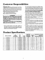 6
6
-
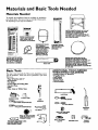 7
7
-
 8
8
-
 9
9
-
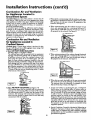 10
10
-
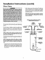 11
11
-
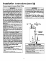 12
12
-
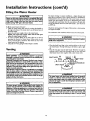 13
13
-
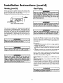 14
14
-
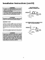 15
15
-
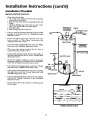 16
16
-
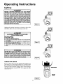 17
17
-
 18
18
-
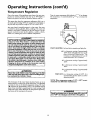 19
19
-
 20
20
-
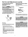 21
21
-
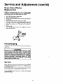 22
22
-
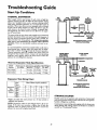 23
23
-
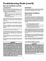 24
24
-
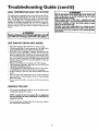 25
25
-
 26
26
-
 27
27
-
 28
28
-
 29
29
-
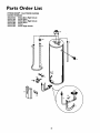 30
30
-
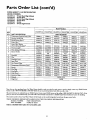 31
31
-
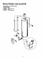 32
32
-
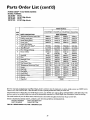 33
33
-
 34
34
-
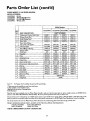 35
35
-
 36
36


Kenmore POWER MISER 9 153.337763 User manual
- Category
- Water heaters & boilers
- Type
- User manual
Ask a question and I''ll find the answer in the document
Finding information in a document is now easier with AI
Related papers
-
Kenmore POWER MISER 9 153.335816 User manual
-
-
-
-
-
-
Sears 153.33429 User manual
-
-
-
Other documents
-
Apollo Hydroheat A650YRRTL5 User manual
-
Reliance Water Heaters 2919340 User manual
-
-
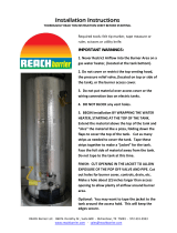 Reach Barrier 3016 Installation guide
-
State Water Heaters P6-30-2OT1 User manual
-
State Water Heaters TW-12 User manual
-
State Water Heaters ES6-20-SOMS-K User manual
-
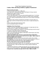 Falcon Stainless SWC1-18 User manual
-
Maytag HJ650POVET2 User manual
-
 Blue Lightning Rod 1017510 Installation guide


