StarTech.com PEXMSATA3422 User manual
- Category
- Interface cards/adapters
- Type
- User manual
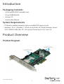
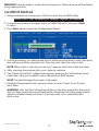
StarTech.com PEXMSATA3422 is a high-performance PCIe SATA III 6Gbps RAID Controller Card that enables you to connect up to 2 mSATA SSDs and 2 SATA drives to your computer through a single PCI Express slot. With support for RAID 0, 1, 10, and JBOD configurations, this card provides increased storage capacity, improved data redundancy, and enhanced performance for demanding applications such as video editing, gaming, and CAD.
StarTech.com PEXMSATA3422 is a high-performance PCIe SATA III 6Gbps RAID Controller Card that enables you to connect up to 2 mSATA SSDs and 2 SATA drives to your computer through a single PCI Express slot. With support for RAID 0, 1, 10, and JBOD configurations, this card provides increased storage capacity, improved data redundancy, and enhanced performance for demanding applications such as video editing, gaming, and CAD.


-
 1
1
-
 2
2
-
 3
3
-
 4
4
-
 5
5
-
 6
6
-
 7
7
-
 8
8
-
 9
9
-
 10
10
-
 11
11
-
 12
12
-
 13
13
-
 14
14
-
 15
15
-
 16
16
-
 17
17
-
 18
18
-
 19
19
-
 20
20
-
 21
21


StarTech.com PEXMSATA3422 User manual
- Category
- Interface cards/adapters
- Type
- User manual
StarTech.com PEXMSATA3422 is a high-performance PCIe SATA III 6Gbps RAID Controller Card that enables you to connect up to 2 mSATA SSDs and 2 SATA drives to your computer through a single PCI Express slot. With support for RAID 0, 1, 10, and JBOD configurations, this card provides increased storage capacity, improved data redundancy, and enhanced performance for demanding applications such as video editing, gaming, and CAD.
Ask a question and I''ll find the answer in the document
Finding information in a document is now easier with AI
Related papers
-
StarTech.com PEXMSATA343 User manual
-
StarTech.com PEXSAT34RH User manual
-
StarTech.com ST2000SPEXI User manual
-
 StarTech.com PEX1PCI1 User manual
-
 StarTech.com PCI1PEX1 Owner's manual
-
 StarTech.com 25SAT35HDD Owner's manual
-
StarTech.com ST10000SPEX User manual
-
 StarTech.com MSAT2SAT3 Owner's manual
-
 StarTech.com 8 Port LP PCIe RS-232 User manual
-


Other documents
-
 Cables Unlimited IOC-7701 Datasheet
-
 Cables Unlimited IOC-7700 Datasheet
-
 Cables Unlimited IOC-7706 Datasheet
-
 Cables Unlimited IOC-7707 Datasheet
-
SIIG LB-US0014-S1 Installation guide
-
M-Cab 7070026 Datasheet
-
StarTech ST1000SPEXD4 User guide
-
 Star Tech Development ST1000SPEX4 User manual
-
StarTech 4 Port 2.5GBase-T Ethernet Network Adapter Card User guide
-
StartTech ST10GSPEXNB2 User guide


