Da-Lite 24727LSR Specification

Category
Projection screens
Type
Specification

Da-Lite 24727LSR is a tensioned Advantage Electrol projection screen, designed for professional installations. It features a motorized operation for easy control and a sleek design that blends seamlessly into any environment. The screen provides accurate color reproduction and wide viewing angles, making it suitable for various applications, including home theaters, conference rooms, and educational institutions. Its sturdy construction ensures durability and longevity, even with frequent use.

Da-Lite 24727LSR is a tensioned Advantage Electrol projection screen, designed for professional installations. It features a motorized operation for easy control and a sleek design that blends seamlessly into any environment. The screen provides accurate color reproduction and wide viewing angles, making it suitable for various applications, including home theaters, conference rooms, and educational institutions. Its sturdy construction ensures durability and longevity, even with frequent use.

INSTRUCTION BOOK FOR
ViewShare Tensioned
Advantage Electrol
2
Tools Required for Installation
1. Hang case and attach to support structure with bolts.
See Suggested Methods of Installation.
2. Tighten bolts until trim lange is lush with ceiling.
NOTE: For proper operation, screen assembly must be level
after installation.
3. Remove 2 screws to open junction box. Install electrical
connections that apply to your unit. Make sure to review the
wiring diagram for proper hook up. Replace junction box cover
and secure with 2 screws.
NOTE: Must be installed in accordance with the requirements of
the Local Building Codes, the Canadian Electrical Code (CEC),
CAN/CSA C22.1 and the National Electric Code (NEC), NFPA 70.
If your case was ordered in advance of the screen and roller
assembly, your installation is now complete. Continue to
step 4 if your Tensioned Advantage Electrol was ordered as a
complete unit.
4. Use supplied 1/8" hex key to remove silver shipping brackets
attached to slat and screen case.
5. Test installation by running screen up and down a few times.
Be prepared to stop screen should any objects obstruct the
movement of the screen. To prevent damage to the motor, the
standard duty cycle is 1 minute on and 3 minutes of.
Case Installation
Important Safety Instructions
When using your video equipment, basic safety precautions
should always be followed, including the following:
1. Read and understand all instructions before using.
2. Position the cord so that it will not be tripped over, pulled, or
contact hot surfaces.
3. If an extension cord is necessary, a cord with a current rating at
least equal to that of the appliance should be used. Cords rated
for less amperage than the appliance may overheat.
4. To reduce the risk of electric shock, do not disassemble this
appliance. Contact an authorized service dealer when repair
work is required. Incorrect reassembly can cause electric shock
when the appliance is used subsequently.
5. The use of an accessory attachment not recommended by the
manufacturer may cause a risk of ire, electric shock, or injury to
persons.
Pre-Installation
1. Carefully unpack case from shipping carton.
2. Set aside the Installation Kit. Items inside will be used during
installation.
3. Make sure to recheck measurement of case for proper
installation clearance.
4. Remove any protective foam covering the outside of
the case.
5. For shipping purposes, foam is also inserted between the roller
brackets and endcaps (Figure 1). Remove these foam blocks from
the ends.
6. Remove the hanger brackets from the top of the case using a 1/2”
wrench. Do not discard the hardware; it will be used during case
installation to re-attach the hanger brackets for mounting.
1/2“ Open Wrench
or Socket Driver
1/8” Hex Key
(included)
3
Suggested Methods of Installation
⅜" Threaded Rod
(Not Supplied)
Hanger Bracket
Electrical
Junction Box
Motor
End
Variable Position
Mounting Bracket
Audience Side
6 ⁄"
6 ⁄"
7 ¾"
⅜" Threaded Rod
(Not Included)
Attached To
Mounting Bracket
Self-Trimming
Flange
Finished
Ceiling
7 ¾"
7 ¾"
8"
6 ⁄"
6 ⅜"
3 ⁄"
7 ⁄"
6 ⁄"
Method 1
Method 2
4
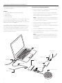
Screen Adjustment for 120V Screens
1. Remove the cover plate from the 3-button wall switch and
remove the switch from the junction box.
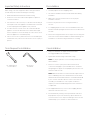
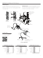
2. Locate small 3-position switch on back of wall switch. See Figure
5 for 120V screens or Figure 8 for 220/240V screens.
3. To adjust the down limit switch, slide the 3-position switch to the
down position. Press and hold the down button to run the screen
down to the desired stop position. Release the button to stop the
screen. DO NOT PUSH THE STOP BUTTON.
CAUTION: Do not adjust for more drop than what was
ordered. At least 11/2 wraps of fabric must remain on the
roller. This screen comes standard with 12" black at the top.
See the speciication data sheet for details.
ATTENTION! N'efectuez pas de réglage pour obtenir un
déroulement supérieur à celui commandé. Au moins 1 à 1/2
tour de toile doit être maintenu sur le cylindre. Ce écran est
doté de série d'une bande noire supérieure de 30,5 cm (12
po).
4. When the screen is in the desired down position, slide the
3-position switch to the of (center) position. The down limit
switch is now set.
5. To adjust the up limit switch, slide the 3-position switch to the up
position. Press and hold the up button to run the screen up to
the desired stop position. Release the button to stop the screen.
DO NOT PUSH THE STOP BUTTON.
Caution: Adjusting the down limit switch by more than 6” can
cause the screen surface to lose proper tensioning.
ATTENTION! Le fait d'ajouter plus de 15 cm (6po) aux
interrupteurs de in de course peut faire perdre la bonne
tension à la surface de l'écran.
6. When the screen is in the desired up position, slide the 3-position
switch to the of (center) position. The up limit switch is now set.
7. To test limit switch setting, make sure the 3-position switch is in
the of (center) position. Press and release the up or down button
on the wall switch to operate the screen.
8. Replace switch and cover plate on the wall.
NOTE: If stop button is pressed, the wall switch will reverse
direction. To correct this, press the stop button again. This will
reset the switch. You will have to re-set both the up and the down
limit settings.
IMPORTANT NOTE: The wall switch is REQUIRED to make any
limit switch adjustments, EVEN if a third party control system is
used. Therefore, it is advised to wire the switch or provide a
4-conductor connection that is accessible.
Screen Adjustment for 220V/240V Screens
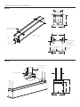
If your Tensioned Advantage Electrol was ordered as a complete unit, the up and down limits were pre-set by Da-Lite. If your screen and
roller assembly was ordered separately from the case, or if general adjustment is needed, please follow the steps below and refer to the
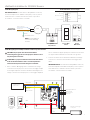
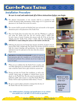
120V Wiring Diagram
1. Locate the wall switch and remove the cover plate from the wall
switch and remove the switch from the junction box.
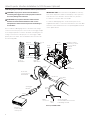
2. Locate the two tactile buttons on the back of the switch. They
are black round buttons on silver plates. See 120V Wiring
Diagram.
3. To adjust the down limit switch, press and hold the down tactile
button until the LED on the back of the switch turns solid red.
This will put the motor in limit set mode. Turn the wall switch over
and use the down button on the front of the switch. Press and
hold the down button until the desired down position is reached.
If you travel too far down, press the up button to move the
screen upward. If you press and let go of either the up or down
buttons, the motor will do a small jog in that direction for ine
adjustment of the screen. Once the desired position is reached,
turn the switch over; press and hold the down tactile button until
the LED on back of switch blinks red twice. The down limit is now
set.
CAUTION: Do not adjust for more drop than what was
ordered. At least 11/2 wraps of fabric must remain on the
roller. This screen comes standard with 12" black at the top.
ATTENTION! N'efectuez pas de réglage pour obtenir un
déroulement supérieur à celui commandé. Au moins 1 à 1/2
tour de toile doit être maintenu sur le cylindre. Ce écran est
doté de série d'une bande noire supérieure de 30,5 cm (12
po).
NOTE: If the screen is in limit set mode and no buttons are
pushed for 20 seconds, the LED on the back of the wall switch
will turn of, the motor will return to run mode and no changes
will be saved. If this occurs, return to step 3 for down limit
adjustment or step 4 for up limit adjustment.
4. To adjust the up limit switch, press and hold the up tactile button
until the LED on the back of the switch turns solid green. This will
put the motor in limit set mode. Turn the wall switch over and
use the up button on the front of the switch. Press and hold the
up button until the desired up position is reached. If you travel
too far up, press the down button to move the screen downward.
If you press and let go of either the up or down buttons, the
motor will do a small jog in that direction for ine adjustment of
the screen. Once the desired position is reached, turn the switch
over; press and hold the up tactile button until the LED on back
of switch blinks green twice. The up limit is now set.
CAUTION: Adjusting the down limit switch by more than 6”
can cause the screen surface to lose proper tensioning.
ATTENTION! Le fait d'ajouter plus de 15 cm (6po) aux
interrupteurs de in de course peut faire perdre la bonne
tension à la surface de l'écran.
5. To test the limit switch settings, press and release the up or down
buttons on the switch to operate the screen.
6. Replace the switch and cover plate on the wall.
IMPORTANT NOTE: The wall switch is REQUIRED to make any
limit switch adjustments, even if a third party control system is
used. Therefore, it is advised to wire the switch or provide a
3-conductor connection that is accessible.
5
RJ45
Receptacle
RJ25
Output
RJ25
Inputs
Up (Dry Contact)
Down (Dry Contact)
Common (Both)
Bus (Bus)
5V (Bus)
UP
STOP
DOWN
BUS
COM
5V
Front of
Wall Switch
Bus
UP
STOP
DOWN
BUS
COM
5V
Led
Up Limit
Tactile Button
Down Limit
Tactile Button
Back of
Wall Switch
Wall Switch Installation for 120V Screens
RJ25 Pin-Outs (Tab Is Facing Up)
Standard RJ25 can be used in place of RJ14 cable
Bus (RP Data)
+12V
RQ Clock
RQ Data
+5V
Ground
Yellow
Red
Black
White
Blue
RJ45 Pin-Outs (Tab Is Facing Up)
+12V
Manual 2
Ground
Manual 1
RQ Clock
Bus (RP Data)
RQ Data
+5V
Blue
Green
Yellow
Red
Black
Orange
Purple
Brown
120V Wiring Diagram
3-conductor 2024 gauge wire can be used in place of the
supplied RJ14 cable to connect the wall switch. Connect the BUS
terminals on the wall switch to the corresponding BUS terminals
on the splitter board.
IMPORTANT NOTE: The wall switch is REQUIRED to make any
limit switch adjustments, EVEN if a third party control system is
used. Therefore, it is advised to wire the switch or provide a
3-conductor connection that is accessible.
UP
STOP
DOWN
BUS
COM
5V
Power Input 120VAC / 60Hz
Green (Ground)
(Ground–Must be Connected
to Building Ground)
Black
(Hot)
White
(Common)
Power
Wire
Data
Cable
RJ45 Jack
RJ25 Jack
(Connection to
Wall Switch)
RJ25
Jack
RJ14 Pin-Outs (Tab Is Facing Up)
Supplied RJ14 cable
Bus (RP Data)
RQ Data
+5V
Ground
White
Green
Red
Black
Installation Video
To view a video of this installation,
visit http://youtu.be/t2ZQ9PVAhEg
or use the QR code below.
Green
6
RJ45
Receptacle
RJ25
Output
RJ25
Inputs
Up (Dry Contact)
Down (Dry Contact)
Common (Both)
Bus (Bus)
5V (Bus)
UP
STOP
DOWN
BUS
COM
5V
Front of
Wall Switch
Bus
UP
STOP
DOWN
BUS
COM
5V
Led
Up Limit
Tactile Button
Down Limit
Tactile Button
Back of
Wall Switch
UP
STOP
DOWN
BUS
COM
5V
Power Input 120VAC / 60Hz
Green (Ground)
(Ground–Must be Connected
to Building Ground)
Black
(Hot)
White
(Common)
Power
Wire
Data
Cable
RJ45 Jack
RJ25 Jack
(Connection to
Wall Switch)
RJ25
Jack
Video Projector Interface Installation for 120V Screens (Optional)
5/12 Volt
Screen Trigger
on Projector
Black
Red
VPI Trigger
Module
120V Wiring Diagram with Optional Built-In Video Projector Interface
CAUTION: The projector must be turned of before
connecting the trigger wires to the projector. Failure to
do so may damage the controller.
ATTENTION: Le projecteur doit être éteint avant de
brancher les ils de déclenchement à celui-ci. Tout
manquement à cette instruction pourrait endommager
le contrôleur.
Use 2-conductor 2024 gauge wire to extend the low voltage
connection from the projector’s 5 or 12-volt screen trigger output
to the length required to reach the VPI. When extending the low
voltage connection from the projector’s screen trigger output
polarity does not matter. The red and black wires from the VPI
are interchangeable.
IMPORTANT NOTE: The wall switch is REQUIRED to make any
limit switch adjustments, EVEN if a third party control system is
used. Therefore, it is advised to wire the switch or provide a
3-conductor connection that is accessible.
3-conductor 2024 gauge wire can be used in place of the
supplied RJ14 cable to connect the wall switch. Connect the BUS
terminals on the wall switch to the corresponding BUS terminals
on the splitter board.
7
240V Wiring Diagram
IMPORTANT NOTE: The wall switch is REQUIRED to make any
limit switch adjustments, EVEN if a third party control system is
used. Therefore, it is advised to wire the switch or provide a
4-conductor connection that is accessible.
Wall Switch Installation for 220/240V Screens
ILT RJ9 Pin-Outs (Tab Is Facing Up)
Ground Common
IR or Up
+5V
Data or Down
Red
White
Black
240V Wiring Diagram with Optional Built-in Video Projector Interface
CAUTION: The projector must be turned of before
connecting the trigger wires to the projector. Failure to do so
may damage the controller.
ATTENTION: Le projecteur doit être éteint avant de brancher
les ils de déclenchement à celui-ci. Tout manquement à
cette instruction pourrait endommager le contrôleur.
1. Use 2-conductor 2024 gauge wire to extend the low voltage
connection from the projector’s 5 or 12-volt screen trigger output
to the length required to reach the VPI. When extending the low
voltage connection from the projector’s screen trigger output, be
sure to maintain the proper polarity. The red wire from the VPI is
the “signal” and the black wire from the VPI is the “ground”.
2. Connect the wires from the VPI that are labeled “Low Voltage
Connection” to the end of the extended screen trigger wires
above.
IMPORTANT NOTE: The wall switch is REQUIRED to make any
limit switch adjustments, EVEN if a third party control system is
used. Therefore, it is advised to wire the switch or provide a
4-conductor connection that is accessible.
240VAC/ 50Hz
Power Source
5/12 Volt Screen Trigger
on Projector
Red
Red
White
Black
Black
Brown (Hot)
Green/Yellow (Ground)
Brown (Down)
Blue (Common)
Black (Up)
Green/Yellow
(Ground)
Blue (Common)
Front of Wall
Switch
Back of
Wall Switch
UP DN
UP
+5V
COM
DN
UP
STOP
DOWN
GND
+5V
3POSITION
SWITCH RJ9
RJ9RJ9
Motor
Front of Wall
Switch
Splitter
Dry Contacts
Back of
Wall Switch
Green
Brown (Hot)
Blue (Common)
NOTE: Ground–Must be
Connected to Building
Ground
Ground to Case
Green
Power Input
240VAC / 50Hz
Green
8
Camera and Speakerphone Installation
The following components are necessary for camera and
speakerphone installation.
Included:
Local CAT5 to USB Extender with Power Supply
6’ USB Cable
USB Speakerphone
Powered USB Hub
You also will need enough CAT5 or CAT5e network cable to run
from the ViewShare Advantage to the Local CAT5 to USB
Extender. THE CAT5 CABLE IS NOT PROVIDED. The length of the
CAT5 cable cannot exceed 200 feet.
For computer system requirements, speciications and
troubleshooting, see the separate camera instruction located in
the Installation Kit and the Speakerphone instruction located
inside the Speakerphone box. Additionally, links to online
assistance for each device are located in the Troubleshooting
section of this instruction book.
Connections (see wiring diagram below)
1. Plug your CAT5 cable into connection port located on the left
end of the ViewShare Advantage (Figure 1).
2. Connect your CAT5 cable to the Local CAT5 to USB Extender,
which should be located near your computer. Connect the Local
CAT5 to USB Extender power supply at this time.
NOTE: The CAT5 cable should only be connected between the
ViewShare Advantage and the Local CAT5 to USB Extender. Do
not connect to a server or network.
3. Lower the ViewShare Advantage screen and note the camera
location in the center of the slat bar (Figure 2).
4. Use the 6’ USB Cable to connect the Local CAT5 to USB Extender
to the USB Hub.
5. Connect the Speakerphone to the Powered USB Hub.
6. Connect the USB Hub to your computer. Connect the USB Hub
power supply at this time.
NOTE: The computer may recognize the USB Hub as a new
component but It does not require any additional drivers. The
USB Hub does not need to be used if your computer has two
open USB ports.
CAT5 Connection
To Screen
120 Volt Power
Video Cable
to Projector
120 Volt Power
Local CAT5 to
USB Extender
USB Cables
6' USB Cable
Powered
USB Hub
Laptop
USB Speakerphone
9
Camera and Speakerphone Installation (continued)
Camera and Speakerphone Setup
You are now ready to run the initial camera setup. The computer
will recognize the camera as a new component and load the
appropriate drivers. This can take up to several minutes and you
may need to follow on-screen instructions. If the computer is
using Windows 7 or later version, the computer will automatically
detect the camera, choose the proper drivers, and install the
drivers without your input. Once the green LED on the Local
CAT5 to USB Extender is illuminated and the drivers are installed,
you are ready to use the camera.
CAT5 Connection
Figure 2Figure 1
If the LED does not turn green after install, your computer may
need to be restarted before the camera can be used. This could
be a result of the type of operating system and other hardware/
software installed, and is not necessarily a faulty device.
1. Open Lync, Skype or other compatible video calling software.
2. Go to the options menu and select “C930e” under the video
devices.
NOTE: The Da-Lite bowtie around the camera will glow when the
camera is selected. If the window says "No camera detected", go
back to the Connections section and check each step.
3. In your software’s options menu, select “Speakerphone 410”
under the audio devices.
Installation is now complete and you are now ready to use your
compatible video calling software.
10
Troubleshooting
Visit www.da -lite.com/products/tutorials.php to ind installation
and troubleshooting tutorials. You will also ind a link to Live Chat
for interactive support.
You can contact us by email at info@da-lite.com or by phone at
800.622.3737 or 574.267.8101 with any additional troubleshooting
questions.
Symptom Cause Solution
Screen will not operate
and motor does not hum.
Incorrect line voltage.
Verify 115125V (or 220240V). If insuicient voltage, rewire
incoming electric line.
Blown fuse. Replace fuse.
Tripped circuit breaker. Reset circuit breaker.
No power to operating switch
or junction.
Check above. Tighten all loose wire connections. Correct any
improper connections.
Down Position
Check for power across black and white leads.
Up Position
Check for power across red and white leads.
Screen will not operate
and motor does not hum.
Power at junction box.
Thermal overload tripped. Let motor cool down for 15 minutes. Try again.
Broken wire in the “down” or “up” position. Check for continuity. Cut o old splice and reconnect.
Defective motor, limit switch or capacitor. Replace motor assembly. NOTE: Motor is a sealed assembly.
Capacitor burned out. Replace motor assembly.
Screen does not stop
at correct position.
Limit switch out of adjustment. See Screen Adjustment section.
Noise.
NOTE: Screen will operate
with a low pitched hum.
Squeaking, rubber end plug rubbing on motor. Center roller in case.
Grinding. Foreign object in screen rubbing on roller
or fabric.
Remove.
Gear noise. Replace motor assembly.
Coasting. Defective brake. Replace motor assembly.
Fabric hangs crooked.
Screen not installed properly. Check for level and plumb.
Fabric has backed up inside case.
Adjust “down” limit switch slowly until roller is exposed and
wrinkle comes out, then readjust for proper drop.
Fabric is damaged. Replace fabric.
Camera Support: http://www.logitech.com/en-us/support/webcam-c930e-business?crid=405&osid=14&bit=64
Speakerphone Support: http://www.jabra.com/support/Jabra-SPEAK410MS_7410109
LIMITED WARRANTY – VIEWSHARE PRODUCTS
Milestone AV Technologies LLC warrants its Da-Lite branded ViewShare products to the original purchaser only, to be free from defects
in materials and workmanship in accordance with the following warranty term:
A period of ive (5) years for the Advantage screen and related components; and
A period of three (3) years for the ViewShare camera and related components.
The foregoing warranty will commence upon the date of purchase by the original purchaser and is expressly contingent upon the
products being properly operated according to Da-Lite’s instructions and not damaged due to improper handling or treatment after
shipment from the factory.
This warranty does not apply to equipment showing evidence of misuse, abuse or accidental damage, or which has been tampered
with or repaired by a person other than authorized Da-Lite personnel.
Da-Lite’s sole obligation under this warranty shall be to repair or to replace (at Da-Lite’s option) the defective part of the merchandise.
Returns for service should be made to your Da-Lite dealer. If it is necessary for the dealer to return the screen or part to Da-Lite,
transportation expenses to and from Da-Lite are payable by the purchaser and Da-Lite is not responsible for damage in shipment. To
protect yourself against damage or loss in transit, insure the product and prepay all transportation expenses.
TO THE MAXIMUM EXTENT PERMITTED BY APPLICABLE LAW, THIS WARRANTY IS IN LIEU OF ALL OTHER WARRANTIES, EXPRESS
OR IMPLIED, INCLUDING WARRANTIES AS TO FITNESS FOR USE AND MERCHANTABILITY. Any implied warranties of itness for use,
or merchantability, that may be mandated by statute or rule of law are limited to the above warranty period. This warranty gives you
speciic legal rights, and you may also have other rights, which vary from state-to-state. TO THE MAXIMUM EXTENT PERMITTED BY
APPLICABLE LAW, NO LIABILITY IS ASSUMED FOR EXPENSES OR DAMAGES RESULTING FROM INTERRUPTION IN OPERATION OF
EQUIPMENT, OR FOR INCIDENTAL, DIRECT, OR CONSEQUENTIAL DAMAGES OF ANY NATURE.
In the event that there is a defect in materials or workmanship of a Da-Lite product, you may contact our Sales Partners at PO Box 137,
Warsaw, IN 465810137, (574) 2678101, (800) 6223737.
IMPORTANT: THIS WARRANTY SHALL NOT BE VALID AND DALITE BRANDED PRODUCTS SHALL NOT BE BOUND BY THIS
WARRANTY IF THE PRODUCT IS NOT OPERATED IN ACCORDANCE WITH THE DALITE WRITTEN INSTRUCTIONS.
Keep your sales receipt to prove the date of purchase and your original ownership.
24954
A Milestone AV Technologies Brand
3100 North Detroit Street
Warsaw, Indiana 46582
P: 574.267.8101 or 800.622.3737
F: 574.267.7804 or 877.325.4832
www.da-lite.com
DL–0159 (Rev. 3) 07.14
© 2014 Milestone AV Technologies LLC. Printed in U.S.A.
  • Page 1 1
  • Page 2 2
  • Page 3 3
  • Page 4 4
  • Page 5 5
  • Page 6 6
  • Page 7 7
  • Page 8 8
  • Page 9 9
  • Page 10 10
  • Page 11 11
  • Page 12 12

Da-Lite 24727LSR Specification

Category
Projection screens
Type
Specification

Da-Lite 24727LSR is a tensioned Advantage Electrol projection screen, designed for professional installations. It features a motorized operation for easy control and a sleek design that blends seamlessly into any environment. The screen provides accurate color reproduction and wide viewing angles, making it suitable for various applications, including home theaters, conference rooms, and educational institutions. Its sturdy construction ensures durability and longevity, even with frequent use.

Ask a question and I''ll find the answer in the document

Finding information in a document is now easier with AI