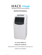
PAC9D

Thermalzone PAC9D, PAD9 Owner's manual

  • Hello! I am an AI chatbot trained to assist you with the Thermalzone PAC9D Owner's manual. I’ve already reviewed the document and can help you find the information you need or explain it in simple terms. Just ask your questions, and providing more details will help me assist you more effectively!
D
D
U
U
A
A
L
L
-
-
P
P
I
I
P
P
E
E
P
P
O
O
R
R
T
T
A
A
B
B
L
L
E
E
A
A
I
I
R
R
C
C
O
O
N
N
D
D
I
I
T
T
I
I
O
O
N
N
E
E
R
R
M
M
O
O
D
D
E
E
L
L
S
S
:
:
P
P
A
A
C
C
9
9
D
D
950-0013-revE Dec. 26, 2006
Page 1 of 19
CONTENTS
FOREWARD 2
INTRODUCTION 3
PART IDENTIFICATION 4
CONTROL PANEL AND DISPLAY SCREEN 5
REMOTE CONTROL 6
CONTROL PANEL USE AND FUNCTIONS 7
TIME SET FUNCTION 8
WATER DRAINAGE METHODS 8
MAINTENANCE AND SERVICE 10
SAFETY 11
TROUBLESHOOTING 12
INSTALLATION 13
SPECIFICATIONS 18
WARRANTY 19
Forward:
Portable Air conditioners should be installed by a professional.
Please read carefully the sections corresponding to the specific model you
choose, and store the manual in a safe place, so as to facilitate your reference
at a later time.
Attention:
(1) The appliance is not intended for use by young children, or without supervision.
(2) Young children should be supervised to ensure that they do not play with
the appliance.
(3) The LCDI plug should be accessible after installation of the appliance.
(4) The appliance shall be installed in accordance with national wiring
regulations.
(5) The appliance should not be installed in areas of excessively high humidity.
(6) If the supply cord is damaged, it must be replaced by a qualified person in
order to avoid a hazard.
(7) Please wait three minutes before restarting after loss of power.
WARNING
This symbol refers to a hazard or unsafe practice which can result in severe
personal injury or death.
CAUTION
This symbol refers to a hazard or unsafe practice which can result in personal
injury or product or property damage.
Page 2 of 19
MOBILE AIR CONDITIONER
This Mobile Air Conditioner is a small size appliance, which can adjust the
temperature and humidity in a room. Its flexibility characteristics make it easily
used in different applications or in different rooms. It also has multiple functions,
including cooling, dehumidifying and fan ventilation. This unit was designed
especially to be used in homes, offices, etc. It has a compact design compared
to others with the same cooling capacity. This unit provides excellent
functionality with low power consumption and a low noise level(less than
58db/a).
Other air conditioning units are recommended when the indoor temperature is
either below 63°F (17°C) or above 95°F (35°C).
MOBILE AIR CONDITIONER
ATTENTION:
Before you use your PORTABLE AIR CONDITIONER, please read this
instruction manual carefully and familiarize yourself with the functions and
operation of the unit.
Page 3 of 19
Page 4 of 19
CONTROL PANEL
DISPLAY (HEAT PUMP MODEL ONLY)
DISPLAY (COOL ONLY MODEL)
Page 5 of 19
IF REMOTE IS LOST:
Unplug unit for 10 seconds, then reconnect power. Unit will now function via the
control panel.
Page 6 of 19
POWER SOURCE
The AC outlet must be a 3 prong grounded outlet using the provided
LCDI power cord.
Do not connect the portable air conditioner to a multiple socket outlet
which is also being used for other electrical appliances.
Insert the AC power plug securely into the AC outlet before using the
unit, when it beeps after two seconds, press ON/OFF button, unit will
begin to run.
LCDI PLUG
(add LCDI Plug Text here)
COOLING OPERATION
1. Press Power button to turn unit on.
2. Repeatedly press MODE button to choose the cooling mode. LCD display
will show “COOL”.
3. Repeatedly press TEMP + or TEMP - button to set a proper room
temperature (63° to 88°F). (17° to 31° C) LCD display will show temperature for
5 seconds before returning to actual room temperature. Display on remote will
always show set temperature.
4. Press FAN SPEED button to choose a proper fan speed, high, medium, or
low speed.
4. Press SWING button to adjust the air flow direction (left or right), The LCD
display will show the swing icon.
5. The operating ranges for cooling operation is 63°F-88°F (17°C-31°C)
Note:
In order to improve the cooling efficiency, be careful that:
If your room is directly exposed to the sun, the shades or drapes
should be drawn.
Do not place near other heat sources.
During the cooling operation, always place the air inlet and exhaust
hose through an open window.
If unit looses power it will restart automatically at previous settings.
If unit is powered off, then powered on again a 3 minute timer will
elapse before cool mode will restart.
DEHUMIDIFYING OPERATION
1. Keep the windows and the doors closed to aid in effectively dehumidifying
the room.
2. Repeatedly press MODE button to choose the dehumidifying mode. LCD
display will show ''DRY''. NOTE: the fan speed cannot be adjusted.
If you choose you may operate unit in dehumidifying mode without the
necessary installation of the air inlet hose, since the air being processed by the
unit comes from within the room itself.
3. The operating range for dehumidifying is 68°F-88°F (20°C-31°C)
Page 7 of 19
ALWAYS REMOVE POWER
(Heat Pump Models Only)
1. Repeatedly press the MODE button to select the heat mode, The LCD
window shows ''HEAT''.
2. Press the TEMP + or TEMP - button to set a proper room temperature
Range. 63°F-88°F (17° to 31° C) .
3. Press FAN SPEED button to choose high, middle, or low fan speed.
4. Press SWING button to adjust the air flow direction, The LCD display will
show the swing icon.
TIMER SET FUNCTION
With unit off: pressing timer button on control panel or remote will set length of
time before unit turns on (press the HOUR button repeatedly to select hours
before start up to 12). The LCD window will show the clock on icon, and hours
to start.
With unit on: pressing timer button on control panel or remote will set length of
time before unit turns off (press the HOUR button repeatedly to select hours
before stop up to 12). The LCD window will show the clock on icon, and hours
to stop.
Note:
If timer is activated unit will not start until set time has elapsed.
If you have the power on/off after 12 hours elapsed time, pressing TIMER key
again will cancel the timing.
To lock remote unit and prevent settings being changed you may press the
TEMP+ and TEMP- buttons together for more than two seconds. Keypad will
lock, and the LCD display will show the lock icon. Press the two buttons again
to unlock the keys, and the lock icon will disappear.
RECYCLE PUMP FUNCTION AND WATER DRAINAGE
(Heat Pump model only)
When unit is operating in the DRY mode:
If the water level in the tank is normal, the recycle pump will operate
recirculating the water across the condenser coil, but the water pump
does not.
If the level in the water tank is high, the water pump will operate for 10
minutes.
If the water level drops, after 10 minutes, the machine will continue to
operate in normal working mode.
If the water level is high after 10 minutes, the water pump will stop
working and the machine will turn off, and the WATER FULL lamp on
the control panel will illuminate.
Page 8 of 19
Condensation – Water Removal
This Portable Air conditioner is designed to evaporate the condensation
removed from the interior area. Under certain conditions it is not possible that
the unit will evaporate 100% of the removed moisture. As the unit accumulates
condensation, under normal condition, it will be evaporated through the exhaust
hose.
The unit is designed with a built-in water tank and a pump to remove the
access condensate-water.
Internal Water Level
1. When the water level is in “low” area, the unit will function normally.
2. If the water level is in the “normal” area, the unit will continue to function
normally with the internal recirculation pump operating to evaporate the water
through the exhaust hose. You may hear the pump operate periodically.
3. If the water level is in the “high” area, the unit will function normally and the
water pump will work for 10 minutes. After running for 10 minutes, if the water
level is still in the “high” area, the unit will turn off. The “WATER FULL”
indicator on the control panel will illuminate. If the unit has a LCD, failure
code E5 will display.
Emptying Water Tank
The water can be drained from the unit either by removing the drainage plug
and allowing the water to drain by gravity, or the pump can be used to empty
the tank.
1. When WATER FULL is on, unplug the unit and move to the unit to the
suitable location for draining the tank.
2. If using the gravity drain method, make sure that the drainage plug is located
higher than the drain area before plug is removed. After the tank is emptied,
re-install the drainage plug. This method can be used for continuous draining
of the tank by leaving the plug connected to the drain area.
If using the internal pump to empty the water tank, securely place the drain
hose in the sink. Re-power the unit and press the TIMER and SWING button
simultaneously, the pump will begin to operate. When the water tank is empty,
turn the unit off and unplug the unit.
3. Return the unit to the desired location, restore the power and duct
connections.
4. The WATER FULL indicator should be off and unit will return to normal
operating mode.
Page 9 of 19
ALWAYS REMOVE POWER FROM UNIT BEFORE SERVICING
CLEANING THE AIR FILTER
For more efficient operation air filter must be cleaned regularly. Performance of
this unit is highly affected by a clogged air filter. Air filter should be cleaned
every 2 weeks of operation or sooner if necessary.
To remove the air filter:
1. Directly pull out the air filter as in the figure below.
2. Wash the air filter by immersing it gently into warm (about 104°F) water with
a mild detergent.
3. Rinse filter thoroughly and let dry before re-installing.
4. Install the air filter back to its original position.
If Air Filter is not excessively dirty, a vacuum may be used in place of washing.
CLEANING OF THE AIR CONDITIONER
Outside surface of the unit may be cleaned with a damp cloth, then allow to dry
before operating.
DO NOT use chemical solvents or harsh detergents to clean the outside
surfaces. This may cause discoloration or deformation of the casing parts.
PRIOR TO SEASONAL OPERATION
Check inlets and outlets for obstructions.
Make sure that the air filter is cleaned and properly in place.
NOTE: If the unit is operated with the air filter removed, dust and foreign
objects can enter the unit, causing damage, or inefficient operation.
Page 10 of 19
AFTER SEASONAL OPERATION
After the operational season or when the unit is to be stored,
You should:
1. Turn off the air conditioner and remove the power source.
2. Clean Air Filter and outside of unit as explained earlier.
3. Open the Drain at the bottom rear of the unit.
4. Allow all condensation to drain, then close the drain.
5. Operate the unit for a few hours in fan only mode to dry any
condensation from the inside of the unit.
6. Unit may be covered to prevent dust and dirt from entering unit during
storage.
SAFETY PRECAUTIONS
CAUTION
Do not use in very small confined spaces
Keep out of direct sunlight. Extended periods of exposure to direct
sunlight will cause discoloration of unit.
WARNING
Do not operate in wet or extremely damp areas.
Do not use near Gas appliances, fires, or in the vicinity of flammable
liquids.
SHOCK HAZARD
Inspect Power cord regularly. Replace cord if frayed, broken, or
otherwise damaged.
Turn off unit before unplugging
When unplugging the unit, hold the plug and remove from socket. DO
NOT UNPLUG BY PULLING ON POWER CORD.
Keep away from Televisions, and radios, to avoid the risk of
electromagnetic interference.
Do not block or restrict the Air inlet and outlets.
Do not Tip or turn over. Do not store this unit on its side.
Do not spray unit with Insecticides or other chemicals.
Page 11 of 19
IF YOU ARE HAVING TROUBLE WITH THE OPERATION OF THIS UNIT
PLEASE CHECK THE FOLLOWING BEFORE SEEKING REPAIR OR
SERVICE.
TROUBLE CHECK ACTION
Air conditioner does
not operate at all.
Is there power to the unit?
Is it plugged in?
Did the Circuit breaker or
fuse trip?
Is the timer activated?
Verify power to unit.
Plug unit into the wall
Reset Circuit Breaker or
replace fuse
Change the set time
Cooling efficiency is
not good
Is the air inlet or outlet
blocked?
Are there any other heat
sources in the room?
Is the air filter dirty?
Is the set temp suitable?
Is the fan speed set too low?
Verify that air inlet and outlet
are free from any blockage
Move any other heat sources,
or move unit away from heat
source.
Clean the air filter
Re-adjust the Set
temperature
Re-adjust the fan speed
Too noisy or
Vibrates
Is unit level? Place unit on a flat level
surface
Machine starts and
stops frequently
Is the voltage from the power
source adequate?
Is the air exhaust blocked?
Check Voltage
Adjust Exhaust pipes to
eliminate bends
WARNING
In case of major malfunction, disconnect power immediately, and call for
service.
Major Malfunctions include:
Circuit breaker or Fuse trips continuously
Power cord is warm to the touch or hot.
Abnormal conditions, loud noises, etc.
Self Diagnosis Functions
This unit has built in diagnosis functions. If the unit fails or is operating
incorrectly, check the unit display for error codes.
Error Code Diagnosis or malfunction
E2 Room temperature sensor failure
E3 Coil Sensor Failure
E4 Unit Abnormal
E5 High Water Level
Page 12 of 19
SELECTION OF INSTALLATION LOCATION
Place the Portable air
conditioner in a flat location
where the air outlets are not
blocked. Place the unit at least
20” (500mm) from walls or other
obstacles.
INSTALLING THE AIR INLET AND EXHAUST HOSES
1. Fit one end of the exhaust hose to the exhaust port on the unit. Turn 2-
3 full turns to tighten the hose.
2. Repeat for the Inlet hose.
3. Straiten hoses to window
Note: length of hoses should be between 24” and 70”. Do not extend hoses
longer than 70”.
CAUTION
When mounting, hose should be kept as horizontal as possible. DO NOT
CONNECT INLET AND OUTLET HOSES TOGETHER. Serious damage to
unit can occur.
Page 13 of 19
INSTALLING THE EXHAUST HOSE
If the hose becomes shredded at the end, you may cut the damaged
section off and re-install as before.
Correct mounting shown below, see Fig. 1 Fig.2& Fig.3.
If mounting in the wall the height of the hole should be between 16” and
51”(400mm-1300mm) Note: There two exhaust hoses of this unit, their
installations are same. You can choose any one of the recommended
installations as shown in the diagrams below..
Page 14 of 19
If the air exhaust requires bending, please see the diagrams below.
Incorrect Hose Mounting Fig. 4 (Air exhaust bend too large).
Page 15 of 19
Window Kit Installation
Your Window Kit has been designed to fit most standard “Vertical” and
“Horizontal” window applications. However, it may be necessary for you to
improvise/modify some aspects of the installation procedures for certain
types of windows. Please refer to Fig. 5 & Fig.6 for minimum and maximum
window openings
INSTRUCTIONS: Install (2) screws on to installation board II as shown
below.
Drain Hose Installation
Attach the drain hose to the drain at the lower back of the unit.
Page 16 of 19
INSTALLATION ACCESSORIES (FIG.7)
DESCRIPTION
Flexible Exhaust hose with adapters …………………. (1)
(Kit contains 2 hoses and 2 adapters)
Stretches from 19-1/2” (500 mm) to 78-3/4” (2000mm)
Window Exhaust adapter kit ……………………………..(1)
2 pieces in kit
Adjustable window slider kit ……………………………..(1)
Fits windows from 26-5/8” (675mm) to 48-3/8” (1230mm)
(includes 2 screws)
Page 17 of 19
Product Specifications
PORTABLE AIR CONDITIONER
MODEL
PAC9D
COOLING CAPACITY
9000 BTU
HEATING CAPACITY
N/A
WATERPROOF TYPE
IP20
ELECTRIC SHOCK PROTECTION CLASS
I
RATED VOLTAGE
115 VAC
RATED FREQUENCY
60 Hz
COOLING POWER INPUT
1260 WATTS
COOLING CURRENT INPUT
11.2 AMPS
HEATING POWER INPUT
N/A
HEATING CURRENT INPUT
N/A
INDOOR DISCHARGE AIR FLOW
206 CF/M
RATED POWER INPUT
1420 WATTS
RATED CURRENT INPUT
11.6 AMPS
NOISE LEVEL
58 DB/A
REFRIGERANT TYPE/WT.
R22(1.56 LBS)
WORKING PRESSURE HIGH SIDE
348 PSI
WORKING PRESSURE LOW SIDE
94.2 PSI
NET WT/GROSS WT
88/94.6 LBS
BREAKER SIZE
15 A
UNIT DIMENSIONS (WxHxD)
22.5”x33.2”x17.7”
Product Specifications subject to change without notice.
Page 18 of 19
WARRANTY
International Refrigeration Products warrants that the product supplied is
free from defects in material and workmanship. This warranty is valid as
long as this product is properly handled, installed, operated and serviced in
accordance with the Installation and Operating Instructions shipped with
this unit, and warranty card is completed and mailed no later than 30 days
after date of purchase. All warranty claims must be made within one (1)
year (five (5) years for compressor) from date of purchase (unless national
regulations require a longer registration period).
This warranty provides free replacement of defective parts only. Labor, and
replacement as a result of normal wear and tear are not covered under this
warranty.
Additional claims are excluded, unless required by national regulations.
International Refrigeration Products Inc. is not responsible for incidental,
consequential, direct, or indirect damages, or expenses relating to the use
of, or the inability to use the product for any purpose. Other implied
warranties are excluded.
This constitutes International Refrigeration Products’ warranty obligation
and replaces any and all prior warranties for this product.
INTERNATIONAL REFRIGERATION PRODUCTS INC.
11325 Nations Ford Rd. Charlotte, NC 28134-8393
(704)504-8590 Phone (704)504-3023 Fax
Page 19 of 19
/