Page is loading ...

OO WW NN EE RR ’’ SS GG UU II DD EE
IINNSSTTAALLLLAATTIIOONN GGUUIIDDEE
© 2006 Directed Electronics, N89222 01-06
150 watt POWER INVERTER
with GAME PLATE
MMOODDEELL VVDDCC330011

22
© 2006 Directed Electronics - all rights reserved
TTaabbllee ooff CCoonntteennttss
Table of Contents . . . . . . . . . . . . . . . . . . . . . . . . . . . . . . . . . .2
Non-Transferable Limited Consumer Warranty . . . . . . . . . . . . . . . .4
Cautions . . . . . . . . . . . . . . . . . . . . . . . . . . . . . . . . . . . . . . . . .6
What’s Included . . . . . . . . . . . . . . . . . . . . . . . . . . . . . . . . . . . .7
Principle of Operation . . . . . . . . . . . . . . . . . . . . . . . . . . . . . . .7
Inverter Output Waveform . . . . . . . . . . . . . . . . . . . . . . . . . . . . .8
Power Source . . . . . . . . . . . . . . . . . . . . . . . . . . . . . . . . . . . . .9
Installation of rubber mounting feet . . . . . . . . . . . . . . . . . . . .10
Placement of Inverter . . . . . . . . . . . . . . . . . . . . . . . . . . . . . . .12
Connecting to Power Source . . . . . . . . . . . . . . . . . . . . . . . . . .13
Electrical Connections . . . . . . . . . . . . . . . . . . . . . . . . . . . . . .14
Temporary Battery Connection..............................................15
Permanent Battery Connection .............................................15
Connection to Load ...........................................................16
Caution: Rechargeable Appliances.........................................17
Game Plate Installation . . . . . . . . . . . . . . . . . . . . . . . . . . . . .18
Mounting the Game Plate ....................................................18
Typical Connection Diagram .................................................19
Fuse Replacement . . . . . . . . . . . . . . . . . . . . . . . . . . . . . . . . .19
Operating Tips . . . . . . . . . . . . . . . . . . . . . . . . . . . . . . . . . . . .20
Rated versus Actual Current Draw of Equipment ......................20
Battery Operating Time .......................................................21

© 2006 Directed Electronics - all rights reserved
33
Caution: Low Battery Alarm .................................................22
Troubleshooting . . . . . . . . . . . . . . . . . . . . . . . . . . . . . . . . . . .23
Automatic Protective Features of the Inverter ........................23
Common Problems . . . . . . . . . . . . . . . . . . . . . . . . . . . . . . . . .24
Troubleshooting Guide . . . . . . . . . . . . . . . . . . . . . . . . . . . . . .25
Problem: Lack of power output ............................................25
Problem: Low Output Voltage...............................................27
Problem: Low Battery Alarm On All The Time..........................27
Specifications . . . . . . . . . . . . . . . . . . . . . . . . . . . . . . . . . . . .28

44
© 2006 Directed Electronics - all rights reserved
NNoonn--TTrraannssffeerraabbllee LLiimmiitteedd CCoonnssuummeerr WWaarrrraannttyy
Directed Electronics, Inc. (Directed) promises to the original purchaser that the automotive
video monitor and/or source unit(s) (the Product), excluding accessories, purchased and
installed from a Directed authorized dealer within the ninety (90) days after purchase of the
new vehicle, in which the Product is installed, is free from defects in materials or workman-
ship under normal use and conditions for a period of three (3) years from date of purchase
or the first 36,000 miles as registered on the new vehicle's odometer reading at time of deliv-
ery of the Product for warranty service, whichever occurs first. Product purchased or
installed more than ninety (90) days after the new vehicle is purchased are warranted for a
period of one (1) year from date of purchase of the Product.
Directed promises to the original purchaser that all video accessories will be free from
defects in materials and workmanship under normal use and condition for a period of nine-
ty (90) days after the date of purchase. A sales receipt and/or warranty registration card is
required to provide proof of date of purchase of the Product or accessories.
Should the Product be determined defective during the applicable warranty period, the
Product will be repaired or replaced with a new or comparable reconditioned part(s), at
Directed's option. To obtain warranty service, the Product must be returned to a Directed
authorized dealer along with proof of purchase and installation.
Note: This warranty does not cover labor costs for the removal and reinstallation of the
Product. IN ORDER FOR THIS WARRANTY TO BE VALID, YOUR PRODUCT MUST BE
SHIPPED WITH PROOF OF PURCHASE AND INSTALLATION BY AN AUTHORIZED
DIRECTED DEALER. ALL PRODUCTS RECEIVED BY DIRECTED FOR WARRANTY
REPAIR WITHOUT PROOF OF DIRECTED DEALER INSTALLATION WILL BE DENIED.
This warranty is non-transferable and does not apply to any Product that has been modified
or used in a manner contrary to its intended purpose, and does not cover damage to the
Product caused by installation or removal of the Product. This warranty is VOID if the prod-
uct has been damaged by accident or unreasonable use, negligence, acts of God, neglect,
improper service or other causes not arising out of defect in materials or construction. This
warranty does not cover the elimination of externally generated static or noise, or the cor-
rection of antenna problems or weak television reception, damage to tapes, video games,
software, camcorders, discs, speakers, accessories or vehicle electrical systems, cosmetic
damage or damage due to negligence, misuse, abuse, failure to follow operating instruc-

© 2006 Directed Electronics - all rights reserved
55
tions, accidental spills or customer applied cleaners, damage due to environmental causes
such as floods, airborne fallout, chemicals, salt, hail, windstorms, lightning or extreme tem-
peratures, damage due to accidents, road hazards, fire, theft, loss or vandalism, damage
due to improper connection to equipment of another manufacturer, modification of existing
equipment, use of a faulty tape cartridge or cleaning of the VCR head, or Product which has
been opened or tampered with for any reason or which has been damaged due to alteration
or service performed by anyone other than Directed Electronics, Inc.
ALL WARRANTIES INCLUDING BUT NOT LIMITED TO EXPRESS WARRANTY, IMPLIED
WARRANTY, WARRANTY OF MERCHANTABILITY, FITNESS FOR PARTICULAR PUR-
POSE, AND WARRANTY OF NON-INFRINGEMENT OF INTELLECTUAL PROPERTY
ARE EXPRESSLY EXCLUDED TO THE MAXIMUM EXTENT ALLOWED BY LAW, AND
DIRECTED NEITHER ASSUMES NOR AUTHORIZES ANY PERSON TO ASSUME FOR IT
ANY LIABILITY IN CONNECTION WITH THE SALE OF THE PRODUCT. DIRECTED HAS
ABSOLUTELY NO LIABILITY FOR ANY AND ALL ACTS OF THIRD PARTIES INCLUDING
ITS LICENSED DEALERS OR INSTALLERS. IN NO EVENT WILL DIRECTED ELEC-
TRONICS, INC. BE LIABLE FOR ANY INCIDENTAL, SPECIAL OR CONSEQUENTIAL
DAMAGES (INCLUDING LOSS OF PROFITS), BY PURCHASING THIS PRODUCT, THE
CONSUMER AGREES AND CONSENTS THAT ALL DISPUTES BETWEEN THE CON-
SUMER AND DIRECTED SHALL BE RESOLVED IN ACCORDANCE WITH CALIFORNIA
LAWS IN SAN DIEGO COUNTY, CALIFORNIA.
Some states do not allow limitation on how long an implied warranty lasts. In such states,
the limitations or exclusions of this Limited Warranty may not apply. Some states do not allow
the exclusion or limitation of incidental or consequential damages. In such states, the exclu-
sion or limitation of this Limited Warranty may not apply to you. This Limited Warranty gives
you specific legal rights, and you may have other rights which vary from state to state.
Some states do not allow the exclusion or limitation of incidental or consequential damages.
In such states, the exclusion or limitations of this Limited Warranty may not apply to you.This
Limited Warranty gives you specific legal rights and you may have other rights which vary
from state to state.

66
© 2006 Directed Electronics - all rights reserved
CCaauuttiioonnss
WHEN CONNECTING DIRECTLY TO A BATTERY OR OTHER POWER SOURCE
OBSERVE PROPER POLARITY.
DO NOT EXCEED THE MAXIMUM INPUT VOLTAGE 15 ±0.3 VDC (DIRECT
CURRENT).
ALWAYS DISCONNECT THE INPUT TO THE INVERTER WHEN IT IS NOT IN USE.
REGULARLY CHECK THAT THE INPUT AND OUTPUT CONNECTIONS ARE
TIGHT. LOOSE CONNECTIONS CAN GENERATE HARMFUL HEAT AND/OR
DAMAGE THE INVERTER OR POWER SOURCE.
IMPROPER USE OF THE DEVICE CAN CAUSE DAMAGE OR INJURY AND
EVEN LOSS OF LIFE.

© 2006 Directed Electronics - all rights reserved
77
WWhhaatt’’ss IInncclluuddeedd
150W Power Inverter Game Plate
(4) screws to mount Inverter Fuse ATC 10 amp
(4) Rubber Feet (4) screws to mount Rubber
(4) screws to mount Feet
Game Plate
PPrriinncciippllee ooff OOppeerraattiioonn
The inverter converts power in two stages. The first stage is a DC to
DC converter, which raises the low voltage DC at the inverter input to
145 volts DC. The second stage is the actual inverter stage. It con-
verts the high voltage DC into 115 volts, 60Hz AC. The inverter stage
uses advanced power MOSFET transistors in a full bridge configuration.
This gives you excellent overload capability and the ability to operate
tough reactive loads.

88
© 2006 Directed Electronics - all rights reserved
IInnvveerrtteerr OOuuttppuutt WWaavveeffoorrmm
The AC output waveform of the Inverter is called a "quasi-sine wave"
or a "modified sine wave". It is a stepped waveform that is designed
to have characteristics similar to the sine wave shape of utility power.
A waveform of this type is suitable for a wide variety of applications.
The modified sine wave produced by the Inverter is designed to have
a RMS (root mean square) voltage of 115 volts, the same as standard
household power. Most AC voltmeters (both digital and analog) are
sensitive to the average value of the waveform rather than the RMS
value. They are calibrated for RMS voltage under the assumption that
the waveform measured will be a pure sine wave. These meters will not
read the RMS voltage of a modified sine wave correctly. They will read
about 20 to 30 volts low when measuring the output of the Inverter.
For accurate measurement of the output voltage of the Inverter, a true
RMS reading voltmeter such as a Fluke 87, Fluke 8060A, Beckman
4410, or Triplett 4200 must be used.

© 2006 Directed Electronics - all rights reserved
99
PPoowweerr SSoouurrccee
The power source must provide between 9.5 and 15 ±0.3 volts DC and
must be able to supply sufficient current to operate the load. The
power source may be a battery or a well regulated DC power supply.
As a rough guideline, divide the power consumption of the load (in
watts) by 12 (the input voltage) to obtain the current (in amperes)
the power source must deliver.
EExxaammppllee::
Load is rated at 140 watts.
Power source must be able to deliver: 140/12= 11.66amperes
CCAAUUTTIIOONN::
THE INVERTER MUST BE CONNECTED ONLY TO BATTERIES WITH A NOMINAL OUTPUT
VOLTAGE OF 12 VOLTS. THE INVERTER WILL NOT OPERATE FROM A 6 VOLT BATTERY AND WILL
BE DAMAGED IF IT IS CONNECTED TO A 24 VOLT BATTERY.

1100
© 2006 Directed Electronics - all rights reserved
IInnssttaallllaattiioonn ooff rruubbbbeerr mmoouunnttiinngg ffeeeett
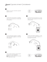
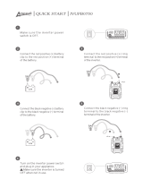
1. Locate plastic bag containing 4 rubber mounting feet and 4 new
screws. Remove from bag.
2. Remove bottom most end cap screws from inverter housing, 2
from each side. See pictures for reference. Discard old screws.
Remove both these screws

© 2006 Directed Electronics - all rights reserved
1111
3. Attach rubber feet to inverter housing end caps using new screws
from bag. Do not over tighten screws, the housing is aluminum and
will strip out easily. Refer to the pictures below for reference.
Remove both these screws

1122
© 2006 Directed Electronics - all rights reserved
PPllaacceemmeenntt ooff IInnvveerrtteerr
For best operating results, the Inverter should be placed on a flat sur-
face, such as the floor or seat of a vehicle. Approximately 20" of cord
have been provided for this purpose. The inverter should only be used
in locations that meet following requirements:
Mount feet on both ends

© 2006 Directed Electronics - all rights reserved
1133
DDRRYY --
do not allow water to drip or splash on the Inverter.
CCOOOOLL --
ambient air temperature should be between 50 and 80 F. Do
not place the Inverter on or near a heating vent or any piece of equip-
ment, which is generating heat above room temperature. Do not place
the Inverter in direct sunlight.
VVEENNTTIILLAATTEEDD --
allow at least one inch of clearance around the Inverter
for airflow. Do not place items on or over the Inverter during opera-
tion. Make sure that air is allowed to circulate freely around the unit.
SSAAFFEE --
do not use the Inverter near flammable materials or in any
location which may accumulate flammable fumes or gases, such as the
battery compartment of your car, truck, RV or boat.
CCoonnnneeccttiinngg ttoo PPoowweerr SSoouurrccee
Connection can also be made directly to the vehicle’s battery. In that
case a 20 amp ATC fuse can be used (not supplied).

1144
© 2006 Directed Electronics - all rights reserved
EElleeccttrriiccaall CCoonnnneeccttiioonnss
The Inverter comes with a cigarette lighter plug adapter for connec-
tion to the power source. The tip of the plug is positive and the side
contact is negative. Connect the plug to the cigarette lighter socket
by pushing in firmly to insure proper contact.
The majority of modern automobiles, RVs, and trucks are negative
ground. Do not use the Inverter with positive ground vehicle electri-
cal systems.
CCAAUUTTIIOONN::
DO NOT USE WITH POSITIVE GROUND VEHICLE SYSTEMS.
CCAAUUTTIIOONN::
CONNECT DIRECTLY TO POWER SOURCE WHEN OPERATING ABOVE 100 WATTS
Most cigarette lighter currents are fused between 10-15 amps. Thus,
connection of the 150W Inverter using the cigarette lighter plug
adapter is suitable for operating the inverter at power outputs up to
approximately 100 watts.
If the inverter is to be used at power levels above 100 watts, direct
connection to the power source is recommended using a hardwire con-
nection.

© 2006 Directed Electronics - all rights reserved
1155
TTEEMMPPOORRAARRYY BBAATTTTEERRYY CCOONNNNEECCTTIIOONN
To make a direct connection, follow these steps:
CCAAUUTTIIOONN::
THE ALLIGATOR CLAMPS COULD COME LOOSE WHILE DRIVING CAUSING POSSIBLE
MECHANICAL/ELECTRICAL DAMAGE.
Convert the 12-volt car cord into a hard wired connection, by con-
necting a cigarette lighter socket to alligator clamps (not supplied)
for temporary use (do not leave alligator clamps on when the vehicle
is being driven).
Then, make a good connection to the power source terminals using
alligator clips. Connect the Red clip to the Positive (+) terminal and
the Black clip to the Negative (-) terminal.
PPEERRMMAANNEENNTT BBAATTTTEERRYY CCOONNNNEECCTTIIOONN
For a permanent connection, use ring terminals of the appropriate size
(one colored RED and one BLACK) (not supplied) in place of the alli-
gator clamps. Observing correct polarity, connect the terminals to the
battery termination posts.
A20 amp ATC fuse can be used in place of the 10 amp ATC fuse (not
supplied) to increase the wattage available from the inverter.

1166
© 2006 Directed Electronics - all rights reserved
CCOONNNNEECCTTIIOONN TTOO LLOOAADD
Once you have determined the proper method of connection to the
power source (cigarette lighter or direct to battery with adapter sock-
et), connect the 150W Inverter accordingly, making sure to fully insert
the plug into the appropriate socket. Now plug appliance(s) into the
receptacle(s) on the Inverter and flip the rocker switch to the (ON)
position. The green LED above it and slightly to the right will illumi-
nate. Turn on your appliance(s) making sure the load requirements are
within the parameters of the Inverter's output
If an audible alarm sounds, that means the power input voltage is too low.
At 9.5V, the PROT (protection) indicator LED will illuminate to red and
the inverter will automatically shut down.
CCAAUUTTIIOONN::
DO NOT CONNECT TO AC DISTRIBUTION WIRING
The Inverter is designed to be directly connected to standard electri-
cal and electronic equipment in the fashion described above. Do not
connect the Inverter to household or RV AC distribution wiring. Do
not connect the Inverter to any AC load circuit in which the neutral
conductor is connected to ground or to the negative of the DC (bat-
tery) source.

© 2006 Directed Electronics - all rights reserved
1177
CCAAUUTTIIOONN:: RREECCHHAARRGGEEAABBLLEE AAPPPPLLIIAANNCCEESS
Certain rechargeable devices are designed to be plugged directly into
an AC receptacle to be recharged. These devices may damage the
Inverter. When first using a rechargeable device monitor its tempera-
ture for the first 10 minutes to ensure that it does not become abnor-
mally hot. That will be your indication that it should not be used with
this inverter.
This problem does not occur with the vast majority of battery operat-
ed equipment. Most equipment of this type uses a separate charger or
transformer that is plugged into the AC receptacle. The Inverter
should have no trouble powering these chargers and transformers.

1188
© 2006 Directed Electronics - all rights reserved
GGaammee PPllaattee IInnssttaallllaattiioonn
MMOOUUNNTTIINNGG TTHHEE GGAAMMEE PPLLAATTEE
The front of the game plate snaps off to allow the back portion of the
plate to be mounted in a convenient location in the vehicle (such as
the back of the front-center seat arm rest). Make sure that the loca-
tion you pick will allow the AC cord from the plate to reach the invert-
er.
4-MOUNTING
SCREWS

© 2006 Directed Electronics - all rights reserved
1199
TTYYPPIICCAALL CCOONNNNEECCTTIIOONN DDIIAAGGRRAAMM
The diagram below shows typical types of connections.
FFuussee RReeppllaacceemmeenntt
Should the blade type 10-amp fuse in the inverter fuse socket blow,
remove the plastic cover and replace with the spare fuse provided or
equivalent. Determine the cause of the problem and remedy before
attempting to use the unit again.
AC PLUG TO INVERTER
AC POWER SOCKET
FOR GAME CONSOLE OR
OTHER DEVICE
POWER ON/OFF SWITCH
AUDIO AND VIDEO
RCA PHONE CONNECTIONS
FROM: GAME CONSOLE,
OR PMP3520,
OR DMP040/070
AUDIO AND VIDEO
CABLES FROM GAME
PLATE TO AN A/V
SWITCH BOX OR
AUXILARY INPUT ON
A VIDEO SCREEN
OFF ON
VIDEO GAME
110V AC
VIDEO
R
AUDIO
L

2200
© 2006 Directed Electronics - all rights reserved
OOppeerraattiinngg TTiippss
RRAATTEEDD VVEERRSSUUSS AACCTTUUAALL CCUURRRREENNTT DDRRAAWW OOFF EEQQUUIIPPMMEENNTT
Most electrical tools, appliances and audio/video equipment have a
label indicating power consumption in amps or watts. Add up the
power consumption of those items you will be using simultaneously,
keeping the total below the rating of Inverter. If the power consump-
tion is rated in amps, multiply by the AC voltage (115) to determine
the wattage. For example, a power drill rated at 3.2 amps will draw
368 watts, more than the 150W Inverter can handle on a continuous
basis.
Resistive loads are the easiest for the Inverter to drive, though larg-
er resistive loads, such as electric stoves or heaters, usually require
more wattage than the Inverter can deliver continuously. Inductive
loads, such as TV 's and stereos (any device with a coil or transformer
in it), by nature require more current to operate than a resistive load
of the same wattage rating. Induction motors (motors without brush-
es), as well as some televisions, may require 2 to 6 times their
wattage rating to start up. This condition may require repeated "ON
OFF, ON OFF, ON OFF" switching of the power switch on your Inverter
in order to get them "started".
/