Page is loading ...

Safety Instructions & Operator’s Manual for
SCRAMBLER
HYDRO DRIVE
SERIES 6
MODELS
YZ18426BVE
YZ20486BVE
MODEL NUMBER EXPLANATION
Y Z 18 42 6 B V E
MODEL DESIGNATION ENGINE OPTIONS
DRIVE SYSTEM TYPE ENGINE TYPE
ENGINE HORSE POWER * ENGINE MODEL
CUTTING WIDTH SERIES DESIGNATION
Y – SCRAMBLER
Z – Zero Turning Radius
18 – 16 HP Engine
20 – 20 HP Engine
42 - 42” Cutting Deck
48 - 48” Cutting Deck
6 - Series Designation B - Briggs Engine
V – Over Head Valve
E - Electric Start
Thank you for buying a SNAPPER Product! Before operating your SCRAMBLER, read this manual carefully and
pay particular attention to the “IMPORTANT SAFETY INSTRUCTIONS” on Pages 2 - 4. Remember that all power
equipment can be dangerous if used improperly. Also keep in mind that SAFETY requires careful use in
accordance with the operating instructions and common sense!
NOTE: Specifications are correct at time of printing and are subject to change without notice.
* Actual sustained equipment horsepower will likely be lower due to operating limitations and environmental factors.
COPYRIGHT © 2004
SNAPPER – A DIVISION OF SIMPLICITY MFG., INC.
ALL RIGHTS RESERVED
MANUAL No. 5-0406 (I.R. 7/27/04)

2
IMPORTANT SAFETY INSTRUCTIONS
WARNING: This powerful cutting machine is capable of amputating hands and feet and can throw objects that
can cause injury and damage! Failure to comply with the following SAFETY instructions could result in serious
injury or death to the operator or other persons. The owner of the machine must understand these instructions
and must allow only persons who understand these instructions to operate machine. Each person operating
the machine must be of sound mind and body and must not be under the influence of any substance, which
might impair vision, dexterity or judgment. If you have any questions pertaining to your machine which your
dealer cannot answer to your satisfaction, call or write the Customer Service Department at SNAPPER,
McDonough, Georgia 30253. Phone: (1-800-935-2967).
PROTECTION FOR CHILDREN
Tragic accidents can occur if the operator is not alert to the
presence of children. Children are often attracted to the
machine and the mowing activity. Children who have been
given rides in the past may suddenly appear in the mowing
area for another ride and be run over or backed over by the
machine. Never assume that children will remain where you
last saw them.
1. KEEP children out of the mowing area and under the
watchful care of a responsible adult other than the
operator.
2. DO NOT allow children in yard when machine is operated
(even with the blade OFF).
3. DO NOT allow children or others to ride on machine,
attachments or towed equipment (even with the blades
OFF). They may fall and be seriously injured.
4. DO NOT allow pre-teenage children to operate machine.
5. ALLOW only responsible adults & teenagers with mature
judgment under close adult supervision to operate
machine.
6. DO NOT operate blades in reverse. STOP BLADES.
LOOK and SEE behind and down for children, pets and
hazards before and while backing.
7. USE EXTRA CARE when approaching blind corners,
shrubs, trees, or other objects that may obscure vision.
PROTECTION AGAINST TIPOVERS
Slopes are a major factor related to loss-of-control and tip-
over accidents, which can result in severe injury or death. All
slopes require extra CAUTION. If you cannot back up the
slope or if you feel uneasy on the slope, DO NOT mow it. Use
extra care with grass catchers or other attachments; these
affect the handling and the stability of the machine.
1. DO NOT operate machine on slopes exceeding 15
degrees (27% grade).
2. Exercise EXTREME CAUTION on slopes above 10
degrees (18% grade). Turn blades OFF when traveling
uphill. Use a slow speed and avoid sudden or sharp
turns.
3. DO NOT operate machine back and forth across face of
slopes. Operate up and down. Practice on slopes with
blades off.
4. AVOID starting, stopping or turning on slopes. If machine
stops going uphill or tires lose traction, turn blades OFF
and back slowly straight down the slope.
PROTECTION AGAINST TIPOVERS
(Continued From Previous Column)
5. STAY ALERT for holes and other hidden hazards. Tall
grass can hide obstacles. Keep away from ditches,
washouts, culverts, fences and protruding objects.
6. KEEP A SAFE DISTANCE (at least 3 feet) away from edge
of ditches and other drop offs. The machine could turn
over if an edge caves in.
7. Always begin forward motion slowly and with caution.
8. Use weights or a weighted load carrier in accordance
with instructions supplied with a grass catcher. DO NOT
operate machine on slopes exceeding 10 degrees (18%
grade) when equipped with grass catcher.
9. DO NOT put your foot on the ground to try to stabilize the
machine.
10. DO NOT operate machine on wet grass. Reduced
traction could cause sliding.
11. Chose a low enough speed setting so that you will not
have to stop or shift on a slope. Tires may lose traction
on slopes even though the brakes are functioning
properly.
12. DO NOT operate machine under any condition where
traction, steering or stability is doubtful.
13. Always keep the machine in gear when going down
slopes. DO NOT shift to neutral (or actuate hydro roll
release) and coast downhill.
PREPARATION
1. Read, understand, and follow instructions and warnings
in this manual and on the machine, engine and
attachments. Know the controls and the proper use of
the machine before starting.
2. Only mature, responsible persons shall operate the
machine and only after proper instruction.
3. Data indicates that operators age 60 and above, are
involved in a large percentage of mower-related injuries.
These operators should evaluate their ability to operate
the mower safely enough to protect themselves and
others from serious injury.
4. Handle fuel with extra care. Fuels are flammable and
vapors are explosive. Use only an approved fuel
container. DO NOT remove fuel cap or add fuel with
engine running. Add fuel outdoors only with engine
stopped and cool. Clean spilled fuel from machine. DO
NOT smoke.
5. Practice operation of machine with BLADES OFF to learn
controls and develop skills.
6. Check the area to be mowed and remove all objects such
as toys, wire, rocks, limbs and other objects that could
cause injury if thrown by blade or interfere with mowing.

3
IMPORTANT SAFETY INSTRUCTIONS
PREPARATION
(Continued From Previous Page)
7. Keep people and pets out of mowing area.
Immediately STOP blades, STOP engine, and
STOP machine if anyone enters the area.
8. Check shields, deflectors, switches, blade
controls and other safety devices frequently for
proper operation and location.
9. Make sure all safety decals are clearly legible.
Replace if damaged.
10. Protect yourself when mowing and wear safety
glasses, long pants and substantial footwear.
11. Know how to STOP blades and engine quickly
in preparation for emergencies.
12. Use extra care when loading or unloading the
machine into a trailer or truck.
13. Check grass catcher components frequently for
signs of wear or deterioration and replace as
needed to prevent injury from thrown objects
going through weak or worn spots.
SAFE HANDLING OF GASOLINE
To avoid personal injury or property damage, use
extreme care in handling gasoline. Gasoline is
extremely flammable and the vapors are explosive
1. Extinguish all cigarettes, cigars, pipes and
other sources of ignition.
2. Use only an approved fuel container.
3. DO NOT remove fuel cap or add fuel with the
engine running. Allow the engine to cool before
refueling.
4. DO NOT refuel the machine indoors.
5. DO NOT store the machine or fuel container
inside where there is an open flame, spark or
pilot light such as on a water heater or other
appliances.
6. DO NOT fill fuel containers inside a vehicle or
on a truck or trailer bed with a plastic liner.
Always place the containers on the ground
away from the vehicle before filling.
7. Remove gas-powered equipment from the
vehicle or trailer and refuel it on the ground. If
this is not possible, then refuel equipment
using a portable container, rather than a
gasoline dispenser nozzle.
8. DO NOT start gas powered equipment in
enclosed vehicles or trailers.
9. Keep the nozzle in contact with the rim of the
fuel tank or container opening at all times until
fueling is complete. DO NOT use a nozzle lock-
open device
10. If fuel is spilled on clothing, change clothing
immediately.
11. Never overfill a fuel tank. Replace fuel cap and
tighten securely.
OPERATION
1. Mount and dismount machine from left side.
Keep clear of discharge opening at all times.
2. Start engine from operator's seat, if possible.
Make sure blades are OFF and parking brake is
set.
3. DO NOT leave machine with engine running.
STOP engine, STOP blades, SET brake, and
Remove key before leaving operators position
of any reason.
4. DO NOT operate machine unless properly
seated with feet on feet rests or pedal(s).
5. STOP BLADES and ENGINE and make sure
blades have stopped before removing grass
catcher or unclogging mower to prevent loss of
fingers or hand.
6. Blades must be OFF except when cutting grass.
Set blades in highest position when mowing
over rough ground.
7. Keep hands and feet away from rotating blades
underneath deck. DO NOT place foot on ground
while BLADES are ON or machine is in motion.
8. DO NOT operate machine without entire grass
catcher or guards in place and working. DO
NOT point discharge at people, passing cars,
windows or doors.
9. Slow down before turning.
10. Watch out for traffic when near or crossing
roadways.
11. STOP engine immediately after striking an
obstruction. Inspect machine and repair
damage before resuming operation.
12. Operate machine only in daylight or with good
artificial light.
13. Move joystick (if equipped) SLOWLY to
maintain control during speed and directional
changes.
14. Exercise CAUTION when pulling loads. Limit
loads to those you can safely control and attach
loads to hitch plate as specified with SNAPPER
attachment instructions.
15. On slopes, the weight of the towed equipment
may cause loss of traction and loss of control.
When towing, travel slowly and allow extra
distance to stop.
16. DO NOT operate engine in enclosed areas.
Engine exhaust gases contain carbon
monoxide, a deadly poison.
17. DO NOT discharge material against a wall or
obstruction. Material may ricochet back
towards the operator.
18. Only use accessories approved by the
manufacturer. See manufacturer’s instructions
for proper operation and installation of
accessories.

4
IMPORTANT SAFETY INSTRUCTIONS
TOWING
1. Tow only with a machine that has a hitch
designed for towing. DO NOT attach towed
equipment except at the hitch point.
2. Follow the manufacturer’s recommendation for
weight limits for towed equipment and towing
on slopes.
3. DO NOT allow children or others on towed
equipment.
4. On slopes, the weight of the towed equipment
may cause loss of traction and loss of control.
5. Travel slowly and allow extra distance to stop.
MAINTENANCE
1. DO NOT store machine or fuel container inside
where fumes may reach an open flame, spark or
pilot light such as in a water heater, furnace,
clothes dryer or other gas appliance. Allow
engine to cool before storing machine in an
enclosure. Store fuel container out of the reach
of children in a well ventilated, unoccupied
building.
2. Keep engine free of grass, leaves or excess
grease to reduce fire hazard and engine
overheating.
3. When draining fuel tank, drain fuel into an
approved container outdoors and away from
open flame.
4. Check brakes frequently; adjust, repair or
replace as needed.
5. Keep all bolts, nuts and screws properly tight.
Check that all cotter pins are in proper position.
6. Always provide adequate ventilation when
running engine. Exhaust gases contain carbon
monoxide, an odorless and deadly poison.
7. Disconnect negative (black) cable from battery
before performing maintenance or service.
Cranking engine could cause injury.
8. DO NOT work under machine without safety
blocks.
9. Service engine and make adjustments only
when engine is stopped. Remove spark plug
wire(s) from spark plug(s) and secure wire(s)
away from spark plug(s).
10. DO NOT change engine governor speed
settings or overspeed engine.
11. Lubricate machine at intervals specified in
manual to prevent controls from binding.
12. Mower blades are sharp and can cut. Wrap the
blades or wear heavy leather gloves and use
CAUTION when handling them.
13. DO NOT test for spark by grounding spark plug
next to spark plug hole; spark plug could ignite
gas exiting engine.
14. Have machine serviced by an authorized
SNAPPER dealer at least once a year and have
the dealer install any new safety devices.
MAINTENANCE
(Continued From Previous Column)
15. Maintain or replace safety and instruction labels
as necessary.
16. Use only genuine SNAPPER replacement parts
to assure that original standards are
maintained.

TABLE OF CONTENTS
IMPORTANT SAFETY INSTRUCTIONS........................................................................ 2-4
TABLE OF CONTENTS......................................................................................................5
SECTION 1 - FAMILIARIZATION.......................................................................................6
SECTION 2 - OPERATING INSTRUCTIONS............................................................... 7-10
Pre-start Checklist ........................................................................................... 7-8
Rolling Machine w/o Engine Running................................................................7
Starting & Stopping Engine, Propelling Mower ............................................ 8-9
Starting & Stopping Mower Blades....................................................................9
Starting & Stopping Wheel Drive........................................................................9
Setting & Releasing Parking Brake ....................................................................9
Cutting Height Adjustment................................................................................10
Safety Interlock System Checks.......................................................................10
SECTION 3 - MAINTENANCE INSTRUCTIONS ...................................................... 11-14
Service – After First Five Hours........................................................................11
Change Engine Oil ..........................................................................................11
Check Mower Blade........................................................................................11
Check Mower Drive Belt.................................................................................12
Check Transaxle Drive Belts..........................................................................12
Service - Every 25 Operating Hours.................................................................12
Check Engine............................................................................................. 12-13
Check Mower Components............................................................................13
Mower Blade Spindle – Lubrication........................................................ 13-14
Mower Deck Linkage – Lubrication...............................................................14
Front Wheel Bearings - Lubrication..............................................................14
Front Caster Wheel Pivot Shaft .....................................................................14
Parking Brake Pivot Bushings.......................................................................14
Service - Annually ..............................................................................................15
Engine ..............................................................................................................15
Air Filter............................................................................................................15
Oil Filter............................................................................................................15
Engine Oil.........................................................................................................15
Transaxle..........................................................................................................15
Fuel Filter.........................................................................................................15
Storage – Out of Season....................................................................................15
SECTION 4 - ADJUSTMENTS AND REPAIR............................................................ 16-23
Engine Adjustments & Repair...........................................................................16
Mower Deck & Components Adjustments.......................................................16
Mower Drive Belt Adjustment ...........................................................................16
Mower Drive Belt Replacement.........................................................................16
Belt Removal & Replacement...................................................................... 16-17
Blade Brake.........................................................................................................17
Mower Deck Adjustment (Levelness - Side to Side 48” Deck)................ 17-18
Mower Deck Adjustment (Front to Rear Pitch 48” Deck)...............................18
Mower Deck Adjustment (Side to Side, 42” & 48” Decks).............................19
Mower Deck Adjustment (Front to Rear Pitch, 42” Decks)............................20
Mower Deck Timing Rod – (42” Decks) ...........................................................20
Wheel Brake Adjustment...................................................................................20
Mower Blade Wear Limits..................................................................................21
Blade Sharpening...............................................................................................21
Blade Replacement ............................................................................................21
Battery Removal, Installation, Service & Charging.........................................22
New Battery Preparation.............................................................................. 22-23
Battery Testing ...................................................................................................23
Joystick Adjustments ........................................................................................24
TROUBLESHOOTING................................................................................................ 25-26
Maintenance/Replacement Parts......................................................................26
SERVICE SCHEDULE......................................................................................................27
WARRANTY......................................................................................................................28
PRIMARY MAINTENANCE ........................................................................................ 29-32
PRODUCT REGISTRATION FORM.................................................................................33
5
6
Section 1 - FAMILIARIZATION
FIGURE 1.1
1.1 INTRODUCTION
This manual has been prepared for the operator’s of the
SNAPPER SCRAMBLER. Its purpose, aside from
recommending standard operating procedures and routine
service requirements, is to promote SAFETY through the
use of accepted operating practices. Read, Understand
and Follow the IMPORTANT SAFETY INSTRUCTIONS
on Pages 2 - 4 of this manual and All SAFETY messages
on the SCRAMBLER and its attachments before operating.
SNAPPER recommends returning the SCRAMBLER to an
authorized SNAPPER dealer annually for inspection and
addition of any new devices which might upgrade the
safety of the mower.
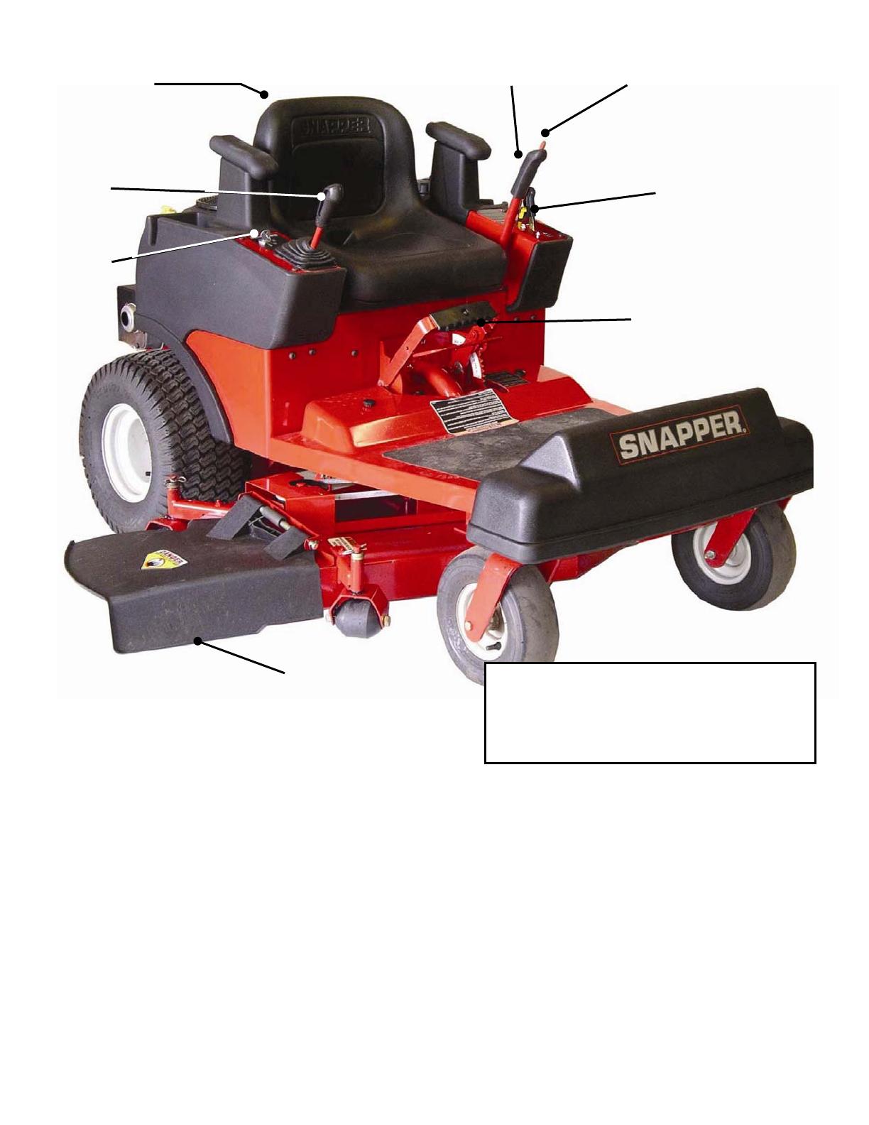
1.2 NOMENCLATURE
The nomenclature drawing above, Figure 1.1, shows the
essential parts of the SNAPPER SCRAMBLER. It is
recommended that all operators of this equipment
become thoroughly familiar with the controls,
components, and operation of this machine before
operating. Specific details involving the engine are
found in the separate engine owner’s manual. Study
these manuals before operating and keep both handy
for future reference. For the nearest SNAPPER dealer in
your area, check the yellow pages under the heading
LAWN MOWERS. For engine parts and service, look
for the engine manufacturer’s dealers under the
heading, ENGINES - gasoline.
KEY
SWITCH
JOYSTICK
CONTROL
HANDLE
OPERATOR’S
SEAT
PARKING
BRAKE
BRAKE
RELEASE
BUTTON
CONTROL PANEL:
ENGINE SPEED & CHOKE
BLADE SWITCH
DECK LIFT
HANDLE
DISCHARGE
DEFLECTOR
IMPORTANT! The figures and illustrations in
this manual are provided for reference only
and may differ from your specific model.
Contact your Snapper dealer if you have
questions
.
7
Section 2 - OPERATING INSTRUCTIONS
2.1 PRE-START CHECK LIST
Make the following checks and perform the service
required before each start-up.
2.1.1. Check tires and add or release air as needed
to bring pressure to 12 P.S.I. in front and 12 P.S.I. in
rear tires.
2.1.2. Check guards, deflectors and covers to make
sure all are in place and securely tightened.
2.1.3. Check engine oil and add oil as needed to
bring level up to the FULL mark. Refer to engine
owner’s manual for oil specifications. See Figure 2.1.
FIGURE 2.1
2.1.4. Check Blade switch to insure it works freely.
Switch is pulled “OUT” into the “ON” position for
blade engagement or pushed back “IN” into the
“OFF” position for blade disengagement. See
Figure 2.2. IMPORTANT: Disengagement stops the
blades rotation.
FIGURE 2.2
2.1.5. Clean exterior surfaces of cutting deck and
engine of any accumulation of dirt, grass, oil, etc.
Keep engine air intake screen and cooling fins clear
at all times.
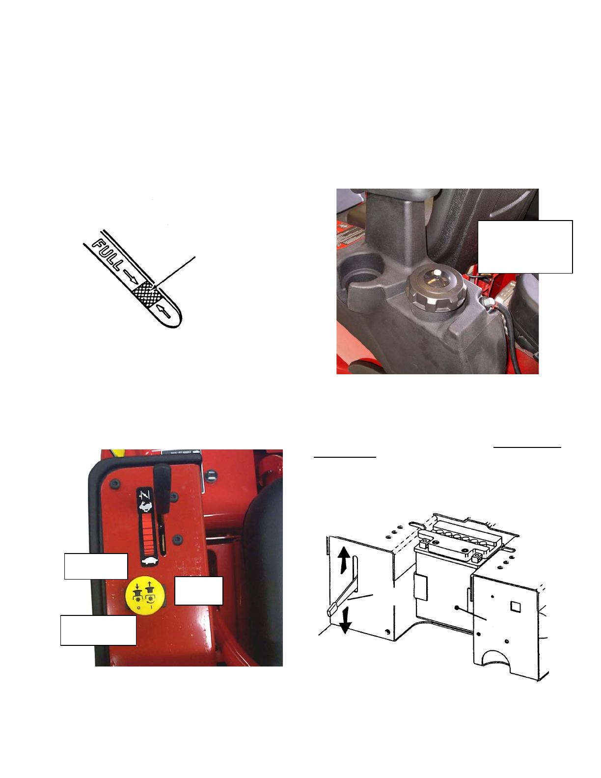
2.1.6. Add fuel to tank of the SCRAMBLER outside
where fumes can safely dissipate. Refer to engine
owner’s manual for fuel specifications. Make sure
fuel filler cap is tight and vent is open after
refueling. See Figure 2.3. Open fuel valve located
in fuel line.
FIGURE 2.3
IMPORTANT: To roll the machine without the engine
running, pressure within the hydraulic pumps must be
released. Tilt seat up and move control lever down to
release pressure. NOTE: Control lever must be in the
“UP” position to drive machine. See Figure 2.4.
DO NOT USE CONTROL TO RELEASE PRESSURE AND
COAST DOWN SLOPES. RELEASE PRESSURE ONLY WHEN
MACHINE MOTION CAN BE CONTROLLED AND ENGINE OFF.
FIGURE 2.4
SAFE LEVEL
AREA
ENGINE OIL DIPSTICK
MOVE CONTROL
LEVER UP TO
DRIVE MACHINE
CONTROL
LEVER
MOVE CONTROL LEVER
DOWN TO ROLL MACHINE
BATTERY
PULL “OUT”
TO ENGAGE
PUSH “IN” TO
DISENGAGE
BLADE
SWITCH
FUEL FILLER CAP
WITH VENT.
TIGHTEN CAP AND
OPEN VENT AFTER
REFUELING.
8
Section 2 - OPERATING INSTRUCTIONS
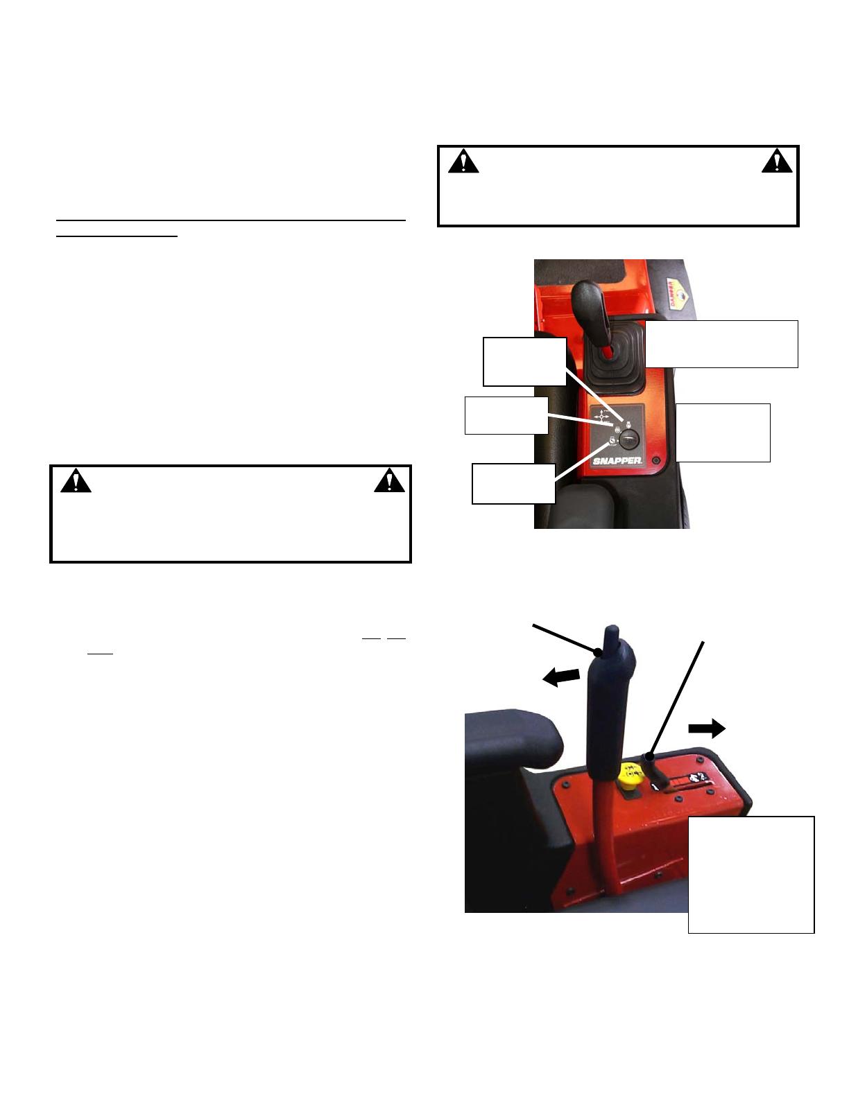
IMPORTANT: This SCRAMBLER is equipped with
hydrostatic drive. The forward, rearward and
steering movement of the machine is controlled by a
joystick lever. Joystick operations should be
performed only from the operator’s position in the
seat. A small movement of the joystick can cause
the machine to move instantly. Move joystick very
carefully and slowly.
1. Always move the joystick to the center position to
“STOP” machine. IMPORTANT: To stop machine
always return the joystick with hand assistance to
the neutral position. Always engage parking brake
when leaving operator’s seat.
2. Move the joystick forward to propel the machine
forward.
3. Move the joystick rearward to propel the machine
backward.
4. Move the joystick to the right to rotate the front of
the machine in circular motion to the right, as in
turning around to go in a different direction.
5. Move the joystick to the left to rotate the front of
the machine in circular motion to the left, as in
turning around to go in a different direction.
WARNING
‘Zero-turning’ the machine at any speed can result in
operator disorientation, or in operator being thrown
from the machine. Exercise extreme caution when
executing a zero-turn.
2.2 STARTING & OPERATION
2.2.1. ENGINE (ELECTRIC START)
IMPORTANT: When the ignition key is turned to
“START”, the engine will not turn over and will
not
start
unless the Parking Brake is engaged and the
Blade Switch is in the “Off” position. The operator
should be in the seat. Start engine as follows:
1. Move joystick lever to (N) Neutral position. See
Figure 2.5.
2. Make certain the blade switch is in the “Off”
position. See Figure 2.6.
3. Make certain the parking brake is engaged. See
Figure 2.5.
4. Open vent on fuel cap by turning
counterclockwise. Open fuel valve located in fuel
line. IMPORTANT: Failure to open vent and fuel
valve will cause engine to stall or not to start.
5. On 42” models, move engine speed control
forward past the “Fast” (Rabbit) position to “Choke”.
See Figure 2.6.
6. On 48” models, move engine speed control
forward to the “Fast” (Rabbit) position and apply
separate choke. See Figure 2.6.
7. Turn key to the “START” position until engine
starts. See Figure 2.5. NOTE: If after 5 seconds of
cranking the engine and it does not start, release the
key. Attempt starting again after waiting for
approximately 20 seconds.
8. After engine starts, turn off choke. Move engine
speed control back to the desired speed position.
Allow a brief warm-up until engine runs smooth.
WARNING
DO NOT leave machine with engine running. STOP
engine. STOP blades. Engage park brake. Remove
key. DO NOT park machine on slopes.
FIGURE 2.5
FIGURE 2.6
(Continued on Next Page)
RUN
POSITION
TURN KEY
TO START
POSITION
JOYSTICK IN NEUTRAL
POSITION
STOP
POSITION
START
POSITION
PARKING BRAKE
ENGAGED
* 48” MODELS ARE
EQUIPPED WITH
SEPARATE CHOKE
CONTROL BEHIND
THROTTLE. PULL
CHOKE CONTROL UP
TO APPLY, PUSH
DOWN TO TURN OFF.
MOVE ENGINE SPEED
CONTROL FORWARD
PAST FAST (RABBIT)
DETENT TO “CHOKE” *
9
Section 2 - OPERATING INSTRUCTIONS
2.2.2. MOWER BLADE
1. With engine running, move engine speed control
to the Rabbit or “Fast” position. (IMPORTANT: On
42” models, be careful not to move control past
“Fast” detent, or choke will engage and engine will
stall.)
2. Pull the blade switch out into the “ON” position
to engage the mower blades. See Figure 2.7.
FIGURE 2.7
3. Release the parking brake. See Figure 2.7.
WARNING
DO NOT operate blades in reverse. STOP Blades.
LOOK and SEE behind and down for children, pets
and hazards before and while backing.
4. Move joystick carefully in the desired direction to
propel the machine. A small movement of the
joystick can cause the machine to move instantly.
Move joystick carefully and slowly.
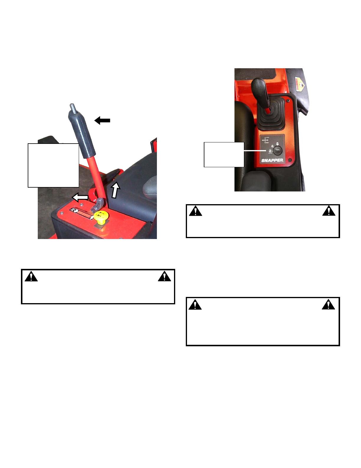
2.3 STOPPING
2.3.1. ENGINE
1. Stop engine by turning key to the “STOP”
position. See Figure 2.8.
FIGURE 2.8
WARNING
DO NOT leave the machine with the engine running.
STOP engine. STOP blades. Engage parking brake.
Remove key. DO NOT park machine on slopes.
2.3.2. WHEEL DRIVE
1. Stop motion of riding mower by moving joystick
to neutral (N) position. See Figure 2.8.
2.3.3. MOWER BLADE
1. Push the blade switch in to “OFF” position to
disengage or stop the mower blades. See Figure 2.7.
WARNING
Blades must stop rotating in 5 seconds or less after
blades have been turned off. DO NOT operate
machine until blade brake has been repaired and
functioning properly. Contact your SNAPPER dealer
for assistance.
2.3.4. PARKING BRAKE
1. Manually position joystick in the neutral position.
2. Engage parking brake by pushing button at the
top of lever and then pulling the parking brake lever
back to the “ON” position.
3. Release parking brake by pushing button at the
top of lever and moving brake lever forward to the
“OFF” position. Refer Figure. 2.7.
TURN KEY
TO STOP
POSITION
MOVE ENGINE
SPEED CONTROL
FORWARD, PULL
BLADE SWITCH
OUT AND
RELEASE PARK
BRAKE

10
Section 2 - OPERATING INSTRUCTIONS
2.3.5. CUTTING HEIGHT ADJUSTMENT
This machine has seven different cutting height
positions. IMPORTANT: When positioning the
cutting deck into a higher cutting position, pull up
on the deck lift handle only, it is not necessary to
pull up on the release lever at the same time. Use
the release lever when moving deck cutting height
to a lower cutting position.
1. Grasp both handles together to disengage
latch.
2. Raise or lower handles to desired height.
3. Release lower handle to engage latch. See
Figure 2.9.
FIGURE 2.9
2.4 SAFETY INTERLOCK SYSTEM CHECKS
This machine is equipped with an electrical safety
interlock system that is provided for the safety of the
operator and others. All safety devices must be in place
and functioning properly before operating the machine.
Perform the following interlock system checks
periodically during the operating season. Contact your
authorized Snapper dealer if you have questions.
WARNING
DO NOT operate machine if any safety interlock or
safety device is not in place and functioning
properly. DO NOT attempt to defeat, modify or
remove any safety device.
ENGINE MUST NOT START IF:
1) Park Brake not in engaged position, OR,
2) Blade Switch in the “ON” blades engaged
position.
ENGINE SHOULD START IF:
1) Blade Switch in the “OFF” blades disengaged
position AND,
2) Park Brake in engaged position.
ENGINE MUST BEGIN TO STOP IF:
1) Operator rises off of seat with Blade Switch in
“ON” blades engaged position OR,
2) Operator rises off of seat with Park Brake not in
engaged position.
IMPORTANT: Engine will continue to run if Operator
becomes seated prior to engine coming to a
complete stop. To restart the blades, first move the
Blade Switch to the “OFF” position and then back to
the “ON” position. After coming to a complete stop,
the blade switch must be moved to the “OFF”
position and the Park Brake engaged before engine
can be restarted. Engine and blades must come to a
complete stop within 5 seconds after the operator
rises off the seat or the blade switch is moved to the
“OFF” position.
DECK LIFT
HANDLE
DECK LIFT HANDLE SHOWN
IN HIGHEST NOTCH.
RELEASE
LEVER
DETENT
PLATE
CONNECTING BAR OMITTED IN THIS
VIEW FOR CLARITY
11
Section 3 - MAINTENANCE
3.1 INTRODUCTION
To retain the quality of the SCRAMBLER, use genuine
SNAPPER replacement parts only. Contact a local
SNAPPER dealer for parts and service assistance. For
the correct part or information for a particular mower,
always mention the model and serial number.
3.2 SERVICE - AFTER FIRST 5 HOURS
WARNING
DO NOT attempt any adjustments, maintenance or
service with the engine or blade running. STOP
blade. STOP engine. Set brake. Remove key.
Remove spark plug wire from spark plug and secure
wire away from spark plug. Engine and components
can be extremely hot. Avoid burns by allowing
engine and components sufficient time to cool.
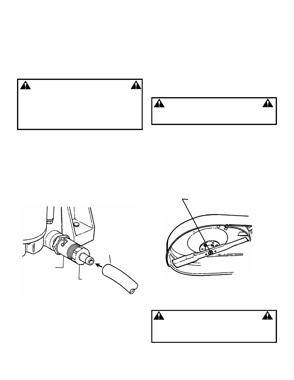
3.2.1. CHANGE ENGINE OIL
1. Place bricks or wooden blocks under the front
wheels to lower rear of engine.
2. Place a 4 quart minimum capacity container
under the end of the oil drain.
3. Loosen or remove oil fill cap on engine.
4. Install the drain hose (Supplied in hardware bag)
onto drain plug nipple and place hose into drain
container.
5. Rotate drain plug counter-clockwise and pull out
to open and allow oil to drain out. See Figure 3.1.
FIGURE 3.1
6. After all the oil has drained, close the drain by
pushing in and rotating clockwise to close. Wipe up
any oil that may have spilled. Dispose of drained oil
properly. See Figure 3.1.
7. Change oil filter at every oil change. Refer to your
engine owner’s manual for service instructions.
8. Fill engine crankcase with new oil. Refer to your
engine owner’s manual for oil specifications.
3.2.2. SERVICE ENGINE AIR CLEANER
The engine is equipped with a dual element air
cleaner. Both the foam pre-cleaner and cartridge
require service. Refer to Engine Owner's Manual
for recommended service procedures.
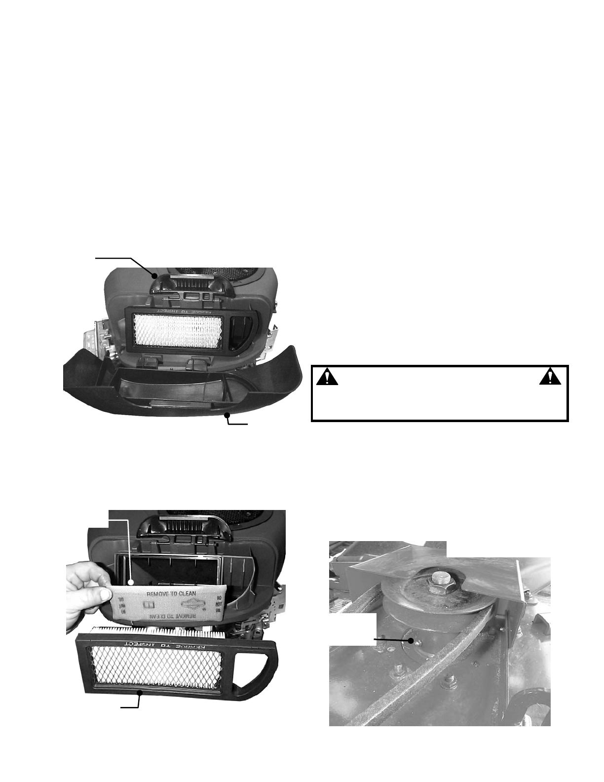
3.2.3. CHECK MOWER BLADE
1. Close vent on fuel cap and make sure cap is
tight.
2. Engage parking brake.
3. Turn key to “STOP” position and remove key from
ignition switch.
WARNING
Wear heavy leather gloves when handling or working
around cutting blades. Blades are extremely sharp and
can cause severe injury.
4. Raise cutting deck to highest setting.
5. With a floor jack, carefully raise front of machine to
gain easier access to under deck. Block machine
securely.
6. Check torque of blade mounting bolts or nuts.
Torque to:
42” Decks -- 30 to 40 ft. lbs.
48” Decks – 80 to 90 ft. lbs.
See Figure 3.2.
7. Check blade for sharpness, wear and damage.
Refer to Section “BLADE WEAR LIMITS”.
FIGURE 3.2
8. Check blade for straightness.
WARNING
DO NOT use a cutting blade that shows signs of
excessive wear or damage. Refer to Section
“MOWER BLADE REPLACEMENT” for proper blade
inspection and service procedures.
INSTALL HOSE
ONTO OIL DRAIN
NIPPLE
OIL DRAIN
ROTATE 1/4 TURN
COUNTERCLOCKWISE
AND PULL OUT TO
DRAIN ENGINE OIL.
BLADE MOUNTING TORQUE:
42” -- 30 TO 40 FT. LBS.
48” -- 80 TO 90 FT. LBS.
TWIN & TRIPLE BLADE DECK

12
Section 3 - MAINTENANCE
3.2.4. CHECK MOWER DRIVE BELT
1. Footrest/Floor pan Removal
a. Pull deck lift handle to highest cutting position.
See Figure 3.3.
b. Remove the two knobs that secure the rear of the
floor pan.
c. Remove two bolts at front bottom edge of foot
rest. Lift up on footrest and slide rear of floor pan out
from under deck lift mechanism.
FIGURE 3.3
2. Checking Mower Belt Tension
The idler and spring provide proper belt tension and
require no adjustment. If belt is frayed, slit, severed or
belt strands exposed, replace belt before operating
mower. Reinstall footrest/floor pan assembly.
3.2.5. CHECK TRANSAXLE DRIVE BELT
1. Checking Transaxle Belt Tension
The transaxle drive belt requires no adjustment. If belt
is frayed, slit, severed or belt strands exposed,
replace belt before operating mower.
3.3 SERVICE EVERY 25 OPERATING HOURS
3.3.1. ENGINE
1. Engine Cooling System
The engine cooling system consists of an engine shroud
and engine fins. These should be kept clean and free of
debris as needed or cleaned.
2. Engine Oil
Change engine oil. See Section on CHANGE ENGINE
OIL. Refer to engine owner’s manual for oil
specifications.
3. Oil Filter
Change engine oil filter. Refer to engine owner’s manual
for filter specifications.
4. Fuel Filter
Refer to engine owner’s manual for service instructions.
5. Air Filter
Refer to engine owner’s manual for service
instructions.
a. 20 Hp Engines: Change air filter. Remove
bolts that secure air cleaner cover. See Figure 3.4.
IMPORTANT: When cover is removed, you are
viewing the carburetor side of the air filter, which will
appear clean. Remove filter and pre-cleaner for
inspection.
FIGURE 3.4
b. Refer to engine owner's manual for cleaning
and service instructions. Remove and clean
engine air pre-cleaner. Remove and replace
engine air cleaner. See Figure 3.5. Install pre-
cleaner and air cleaner per engine owner’s
manual.
FIGURE 3.5
DECK LIFT HANDLE
SHOWN
POSITIONED IN
HIGHEST NOTCH.
RELEASE
LEVER
DECK LIFT
HANDLE
AIR CLEANER
COVER
AIR CLEANER
RETAINING BOLTS
NOTE: YELLOW TABS MUST BE
COMPLETELY INSERTED INTO SLOTS
AIR CLEANER
AIR PRE-
CLEANER
13
Section 3 - MAINTENANCE
3.3 SERVICE EVERY 25 OPERATING HOURS
3.3.1. ENGINE
5. Air Filter
c. Reinstall air cleaner cover. Insert tabs located
on the engine cover into corresponding slots in air
cleaner cover. IMPORTANT: The yellow tabs must
be completely inserted into air cleaner cover or the
compartment will not be completely sealed to
prevent debris from entering into the carburetor.
a. 18 HP Engines: Change air filter. Pull up and
rotate the air cleaner latch to remove cleaner cover.
See Figure 3.4.
IMPORTANT: When cover is removed, you are
viewing the carburetor side of the air filter, which
will appear clean. Remove filter and pre-cleaner for
inspection.
FIGURE 3.4
b. Refer to engine owner's manual for cleaning and
service instructions. Remove and clean engine air
pre-cleaner. Remove and replace engine air
cleaner. See Figure 3.5. Install pre-cleaner and air
cleaner per engine owner’s manual.
FIGURE 3.5
c. Reinstall air cleaner cover. Insert tabs located at
the bottom of the cover into corresponding slots in
engine cover. Position cover and engage latch over
cover and rotate and push down to lock.
3.3.2. MOWER COMPONENTS
1. Mower Drive Belt
Check belt for proper tension. No adjustment
required. Replace belt as needed.
2. Mower Blade
Check blade for sharpness, wear, damage, and
torque. See the section on Mower Blade
Replacement/Repair.
3. Mower Deck Levelness
Check mower deck for proper levelness. Adjust as
required. See section on Mower Deck Adjustment -
Levelness.
4. Cleaning Mower Deck
a. Close vent on fuel cap and make sure cap is
tight.
b. Remove key from ignition switch. Engage
parking brake.
c. Remove spark plug wire(s) and secure away
from spark plug(s).
d. Raise cutting deck to highest setting.
e. With a floor jack, carefully raise up front of
machine to gain easier access to under deck.
Block machine securely.
WARNING
Lifting or lowering the machine onto or down from
blocks manually can cause severe injury. Always
use a floor jack when raising machine.
f. Clean underside of mower deck, removing all
accumulation of grass clippings and debris.
g. Lower SCRAMBLER to ground. Clean top of
deck, removing all grass clippings and debris.
5. Mower Blade Spindle - Lubrication
a. Lubricate spindle bearings with three shots of
general purpose grease from grease gun. See
Figure 3.6.
FIGURE 3.6
LUBRICATE
SPINDLE
BEARINGS
TOP VIEW OF 48” DECK
AIR CLEANER
COVER
AIR CLEANER
LATCH
AIR CLEANER
AIR PRE-
CLEANER
14
Section 3 - MAINTENANCE
WARNING
DO NOT attempt any adjustments, maintenance or
service with the engine or blade running. STOP
blade. STOP engine. Set brake. Remove key.
Remove spark plug wire from spark plug and secure
wire away from spark plug. Engine and components
can be extremely hot. Avoid burns by allowing
engine and components sufficient time to cool.
5. Mower Blade Spindle - Lubrication
b. 42” Deck spindle assemblies are equipped
with a grease fitting located underneath the
deck. Lubricate spindle bearings with three
shots of general purpose grease from grease
gun.
6. Mower Deck Linkage - Lubrication
Lubricate all mower deck linkage pivot points with a
light coat of motor oil.
3.3.3. SCRAMBLER - LUBRICATION
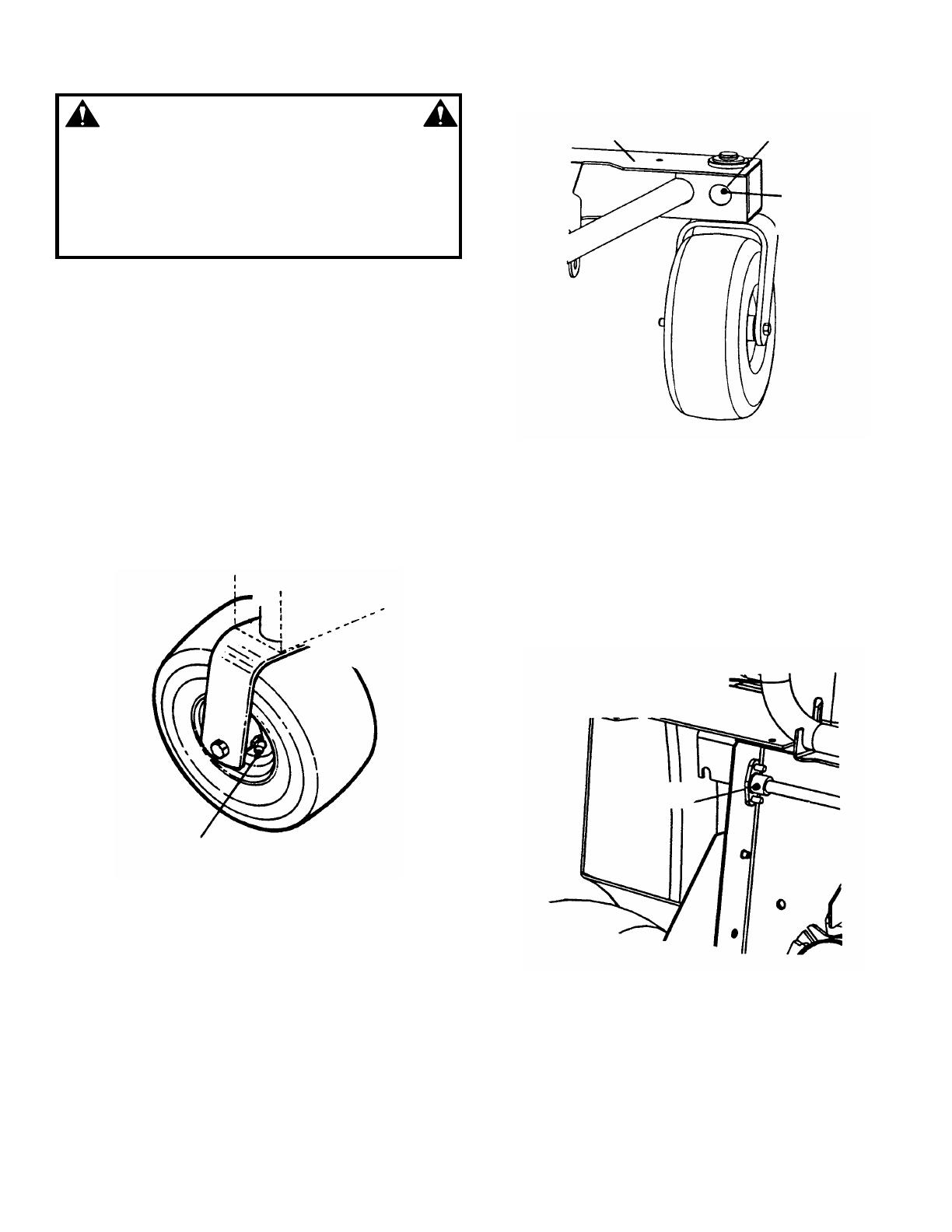
1. Front Wheel Bearings
Lubricate front wheel bearings with five shots of
general purpose grease from grease gun. See
Figure 3.7.
FIGURE 3.7
2. Front Caster Wheel Pivot Shaft
The footrest/floor pan assembly will have to be
removed to lubricate the pivot shaft. The access hole
is at the rear of the front structure underneath the
footrest.
a. The pivot shaft grease fitting can be accessed
through a hole at the rear of the front structure.
Lubricate pivot shaft with three shots of general
purpose grease from grease gun. See Figure 3.8.
FIGURE 3.8
3. Parking Brake Pivot Bushings
a. Remove key from ignition switch.
b. Remove spark plug wire(s) and secure away
from spark plug(s).
c. Drop cutting deck to lowest setting.
d. Lubricate both pivot bushings with three shots
general purpose grease from grease gun. See
Figure 3.9
FIGURE 3.9
SCRAMBLER SHOWN WITH DECK
REMOVED. DECK REMOVAL NOT
NECESSARY FOR LUBRICATION.
LUBRICATE BOTH
PIVOT BUSHINGS
LUBRICATE FRONT WHEEL BEARINGS
FRONT STRUCTURE
ACCESS HOLE
LUBRICATE PIVOT
SHAFTS
FRONT COVER
IS REMOVED
15
Section 3 – MAINTENANCE
3.4 SERVICE - ANNUALLY
Perform all maintenance as described in the maintenance
schedule.
3.4.1. Engine
Service engine according to engine owner’s manual.
3.4.2. Air Filter
Refer to engine owner’s manual for service
instructions.
3.4.3. Oil Filter
Refer to engine owner’s manual for service
instructions.
3.4.4. Engine Oil
Refer to engine owner’s manual for service
instructions.
3.4.5. Transaxle
IMPORTANT: DO NOT try to open reservoir cap
at any time. The transaxle is maintenance free.
The transaxle does not require any fluid or any
service. If there is any problem: leakage,
malfunction or etc. return the SCRAMBLER
immediately to the nearest authorized Snapper
dealer for service.
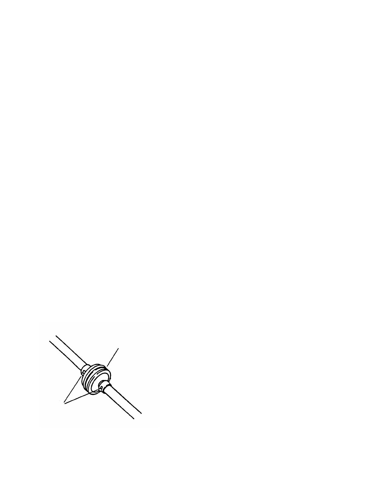
3.4.6. Fuel Filter
Service fuel filter as instructed below. Close fuel
valve in fuel line. Run engine until engine runs out
of fuel. Turn key to “OFF” position. Engine MUST
be stopped and MUST be cold before removing
filter. Perform filter change only when fuel line is
empty.
1. Remove hose clamps from fuel filter.
2. Remove fuel lines from filter. Discard filter.
3. Install new fuel filter. Reinstall hose clamps.
See Figure 3.8.
FIGURE 3.8
3.5 STORAGE (OUT OF SEASON)
Perform the following procedures to insure the
SCRAMBLER will operate properly when taken out of
storage.
3.5.1. Thoroughly clean the SCRAMBLER by
removing all grass clippings and debris.
3.5.2. Perform maintenance and lubrication as
described in the previous sections.
3.5.3. Drain fuel from fuel tank into an approved
container outdoors away from all sources of
ignition.
3.5.4. Start engine and allow it to run until engine
runs out of fuel. This allows the carburetor and fuel
system to remain clean during storage.
3.5.5. Remove battery. Refer to Section
“BATTERY REMOVAL AND STORAGE”.
3.5.6. Close vent on fuel cap and fuel valve in fuel
line. Remove key.
NEW FUEL
FILTER
HOSE CLAMPS
16
Section 4 - ADJUSTMENTS & REPAIR
WARNING
DO NOT attempt any adjustments, maintenance or
service with the engine or blade running. STOP
blade. STOP engine. Set brake. Remove key.
Remove spark plug wire from spark plug and secure
wire away from spark plug. Engine and components
can be extremely hot. Avoid burns by allowing
engine and components sufficient time to cool.
4.1 ENGINE ADJUSTMENTS & REPAIR
Refer to the engine owner’s manual for those adjustments
and/or repairs that can be made by the owner.
4.2 MOWER DECK & COMPONENT ADJUSTMENTS
The following mower deck and component adjustments
and repairs can be made by the owner. However, if
there is difficulty in achieving these adjustments and
repairs, it is recommended that these repairs be made
by an authorized SNAPPER dealer.
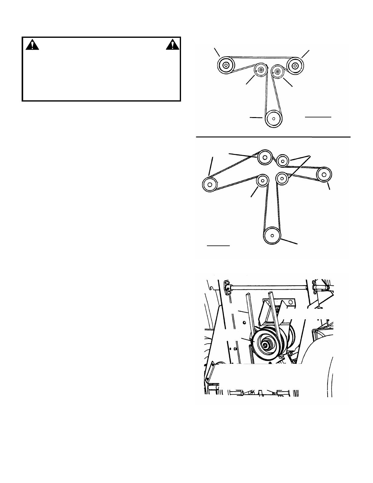
4.2.1. MOWER DRIVE BELT ADJUSTMENT
The 42” and 48”mower deck drive belts do not
require any adjustment. If the belt does not drive
blade properly, replace belt as needed. See
Section “Belt Replacement”. Belt routing shown on
this page. See Figure 4.1.
4.2.2. MOWER DRIVE BELT REPLACEMENT
Inspect mower drive belt. Replace belt if signs of
excessive wear and/or damage are present.
4.2.3. BELT REMOVAL
1. Remove footrest/floor pan assembly.
2. Remove old belt.
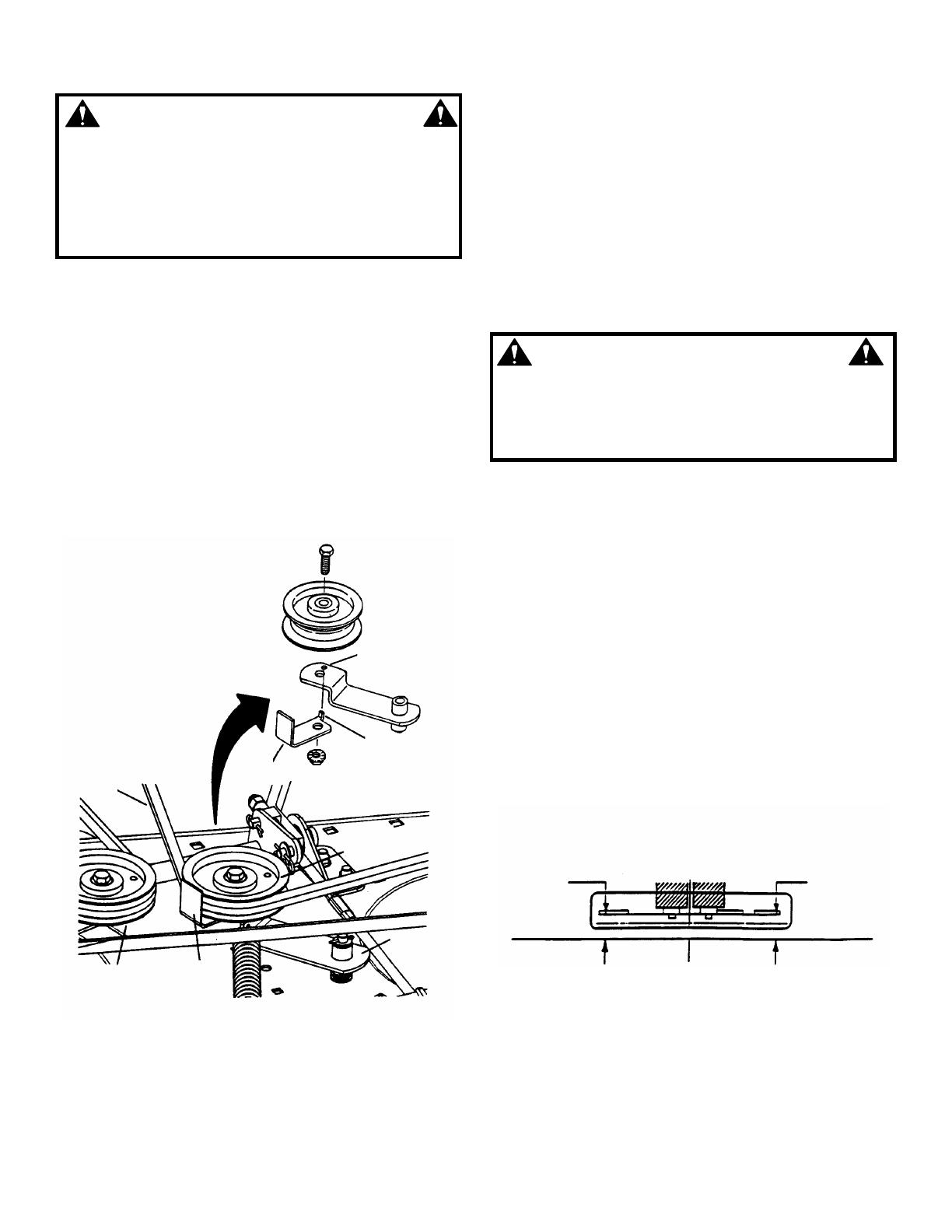
4.2.4. BELT REPLACEMENT
1. Route new belt around electric clutch pulley.
See Figure 4.2.
2. Route belt around stationary idler.
3. Remove spring that is connected to idler pulley.
Loosen nut and bolt that secures idler pulley to idler
arm. Route belt between belt guide and idler pulley.
(Continued On Next Page)
FIGURE 4.1
FIGURE 4.2
SPINDLE PULLEY
IDLER PULLEY
STATIONARY
PULLEY
ELECTRIC CLUTCH
PULLEY
42” DECKS
ELECTRIC
CLUTCH
PULLEY
SPINDLE
PULLEY
STATIONARY
PULLEY
IDLER
PULLEY
SPINDLE
PULLEY
48” DECK
ROUTE MOWER BELT AROUND
ELECTRIC CLUTCH PULLEY
MOWER
BELT
ELECTRIC
CLUTCH
VIEW SHOWN FROM UNDERNEATH WITH DECK
REMOVED, DECK REMOVAL IS NOT NECESSARY
FOR MOWER BELT REPLACEMENT.
SPINDLE PULLEY
17
Section 4 - ADJUSTMENTS & REPAIR
WARNING
DO NOT attempt any adjustments, maintenance or
service with the engine or blade running. STOP
blade. STOP engine. Set brake. Remove key.
Remove spark plug wire from spark plug and secure
wire away from spark plug. Engine and components
can be extremely hot. Avoid burns by allowing
engine and components sufficient time to cool.
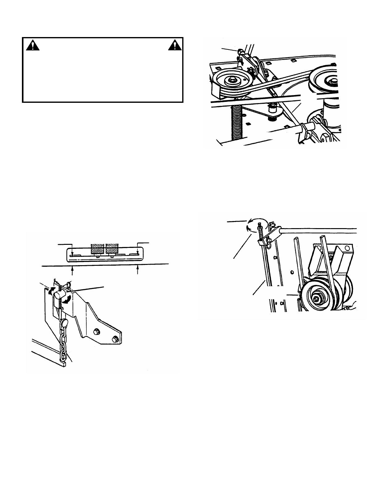
4.2.4. BELT REPLACEMENT
(Continued From Previous Page)
4. Route belt onto spindle pulley. Make sure belt is
inside spindle pulley belt guide.
5. Reinstall idler pulley spring. See Figure 4.3.
NOTE: The idler belt guide should be positioned so
the locator tab fits into the corresponding hole
found on the idler arm. See Figure 4.3. Tighten bolt
securely.
6. Reinstall footrest/floor pan assembly.
NOTE: FOR PART NUMBERS OF REPLACEMENT BELTS,
REFER TO SECTION: ”MAINTENANCE/REPLACEMENT
PARTS”.
FIGURE 4.3
4.2.5. BLADE BRAKE
The blade switch engages the electric clutch when
pulled out to the “ON” position. When the blade
switch is in the “ON” position the cutting blade(s)
are engaged. The blade switch disengages the
electric clutch when the blade switch is pushed in to
the “OFF” position. When the blade switch is in the
“OFF” position the cutting blade(s) are disengaged.
The electric clutch is non-adjustable. The blade(s)
should stop rotation in 5 seconds or less. If the
electric clutch fails to stop the blade(s) rotation in 5
seconds, contact an authorized SNAPPER dealer
to repair or replace.
WARNING
Blades must stop rotating in 5 seconds or less after
blades have been turned off. DO NOT operate
machine until blade brake has been repaired and
functioning properly. Contact your SNAPPER dealer
for assistance.
4.2.6. MOWER DECK ADJUSTMENT (LEVELNESS)
Side-To-Side (48” Decks)
Before making deck leveling adjustments, check
the tire pressure. Add or release air as needed to
bring pressure to 12 P.S.I. in front and 12 P.S.I. in
rear tires. If tires are properly inflated and mowing
is still uneven, adjust side-to-side deck levelness
first as follows:
1. Place SCRAMBLER on a smooth level
surface.
2. Remove footrest/floor pan assembly.
3. Rotate outside blades so tips are pointed to
the sides of deck. See Figure 4.4. Measure the
distance from blade tips to floor. If the
measurement is within 1/8” from side-to-side,
the deck levelness is satisfactory. If the
difference from side-to-side is greater than 1/8”,
continue to Step 4 for adjustment.
FIGURE 4.4
(Continued On Next Page)
IDLER ARM AND BELT
GUIDE DETAIL
42” DECK SHOWN
TAB MUST GO
INTO HOLE
LOCATOR TAB
BELT GUIDE
MOWER
BELT
IDLER PULLEY
IDLER
ARM
BELT
GUIDE
STATIONARY
PULLEY
SIDE SIDE
X
X-1/8”
18
Section 4 - ADJUSTMENTS & REPAIR
WARNING
DO NOT attempt any adjustments, maintenance or
service with the engine or blade running. STOP
blade. STOP engine. Set brake. Remove key.
Remove spark plug wire from spark plug and secure
wire away from spark plug. Engine and components
can be extremely hot. Avoid burns by allowing
engine and components sufficient time to cool.
4.2.6. MOWER DECK ADJUSTMENT (LEVELNESS)
Side-To-Side (48” Decks)
(Continued From Previous Page)
4. Remove hair pin from pivot rod and pull rod
out of lift arm.
5. Rotate pivot rod up or down to achieve the
proper levelness. See Figure 4.5.
6. Reinstall hair pin into pivot rod.
7. Reinstall footrest/floor pan assembly.
FIGURE 4.5
4.2.7. MOWER DECK ADJUSTMENT (LEVELNESS)
Front to Rear Deck Pitch (48” Deck)
Before making deck leveling adjustments, check the
tire pressure. Add or release air as needed to bring
pressure to 12 P.S.I. in front and 12 P.S.I. in rear tires. If
tires are properly inflated and mowing is still uneven,
check side-to-side deck levelness first then proceed
to front to rear adjustment. Adjust front to rear deck
levelness as follows:
1. Place SCRAMBLER on a smooth level
surface.
2. Remove footrest/floor pan assembly.
3. Rotate outside blades so tips are pointed to the
front and rear of deck. Measure the distance from
blade tips to floor. The distance should be the
same, or the rear 1/4” higher than the front. If the
rear blade tip is lower or is more than 1/4” higher
than the front, proceed to Step 4 for adjustment.
4. Remove the hair pin from pivot rod on one side
of deck at a time.
5. Rotate each pivot rod up or down the same
number of turns to achieve the proper levelness.
6. Reinstall both hair pins into pivot rods. See
Figure 4.5.
7. Reinstall footrest/floor pan assembly.
4.2.8. MOWER DECK TIMING ROD - 48” DECKS
The mower deck timing rod is preadjusted at the
factory. It is set to maintain the deck in the same
attitude through all heights of cut. If the timing rod
requires adjustment, contact an authorized
SNAPPER dealer for service.
HAIRPIN
LIFT ARM
PIVOT ROD

19
Section 4 - ADJUSTMENTS & REPAIR
WARNING
DO NOT attempt any adjustments, maintenance or
service with the engine or blade running. STOP
blade. STOP engine. Set brake. Remove key.
Remove spark plug wire from spark plug and secure
wire away from spark plug. Engine and components
can be extremely hot. Avoid burns by allowing
engine and components sufficient time to cool.
4.2.9. MOWER DECK ADJUSTMENT (LEVELNESS)
1. Side-To-Side (42”Decks)
Before making deck leveling adjustments, check
the tire pressure. Check tires and add or release air
as needed to bring pressure to 12 P.S.I. in front and
12 P.S.I. in rear tires. If tires are properly inflated
and mowing is still uneven, adjust side-to-side deck
levelness as follows:
a. Place SCRAMBLER on a smooth level
surface.
b. Turn engine off and remove key, remove
spark plug wire(s) from spark plug(s) and secure
wire(s) away from plug(s).
c. Place a piece of angle iron, pipe, or similar
object under center of deck at the rear.
d. Remove rear hanger chains and allow center,
rear of deck to rest on angle iron.
e. Measure the distance from blade tips to floor. If
the measurement is within 1/8” from side-to-side,
the deck levelness is satisfactory. If the difference
from side-to-side is greater than 1/8”, continue to
the Step “f” for adjustment. See Figure 4.6.
f. Loosen the shoulder bolt that retains the
eccentric.
g. Turn eccentric “UP” or “DOWN” as required
until blade tips are within 1/8” of the same
distance from the floor. See Figure 4.7.
h. Tighten shoulder bolt loosened in Step “f”.
i. Readjust rear hanger chain pivots to align
with holes in support brackets.
j. Reconnect hanger chains, remove angle iron,
pipe, etc. and recheck side to side level. Adjust
either chain as needed to result in blade tips
being within 1/8” of the same distance from the
floor.
k. Proceed to check front to rear deck pitch.
FIGURE 4.7
(Continued On Next Page)
FRONT OR REAR VIEW OF DECK
TWIN BLADE DECK
ANGLE
IRON
X - 1/8”
X
SIDE SIDE
SINGLE BLADE DECK
SIDE SIDE
X - 1/8”
ANGLE IRON
X
42” DECK SHOWN
UP
DOWN
FRONT
LIFT ARM
ECCENTRIC
LOOSEN
SHOULDER
BOLT
FIGURE 4.6
20
Section 4 - ADJUSTMENTS & REPAIR
WARNING
DO NOT attempt any adjustments, maintenance or
service with the engine or blade running. STOP
blade. STOP engine. Set brake. Remove key.
Remove spark plug wire from spark plug and secure
wire away from spark plug. Engine and components
can be extremely hot. Avoid burns by allowing
engine and components sufficient time to cool.
4.2.9. MOWER DECK ADJUSTMENT (LEVELNESS)
(Continued From Previous Page)
2. Front to Rear Deck Pitch (42” Decks)
With the SCRAMBLER on a smooth, level surface,
rotate blades until blade tips are at front and rear of
deck. Measure the distance from blade tips to
floor. The distance should be the same, or the rear
1/4” higher than the front. If the rear blade tip is
lower or is more than 1/4” higher than the front,
proceed with adjustment.
a. Remove rear hanger chains.
b. Turn each hanger pivot the same number of
rotations on the eye-bolt to raise or lower the
rear of the deck. See Figure 4.8.
c. Reinstall rear hanger chains and measure
blade tips again.
d. Repeat steps “a” through “c” until proper
levelness is obtained.
FIGURE 4.8
4.2.10. MOWER DECK TIMING ROD - 42” DECKS
The mower deck timing rod is preadjusted at the
factory. It is set to maintain the deck in the same
attitude through all heights of cut. If the timing rod
requires adjustment, contact an authorized
SNAPPER dealer for service. See Figure 4.9.
FIGURE 4.9
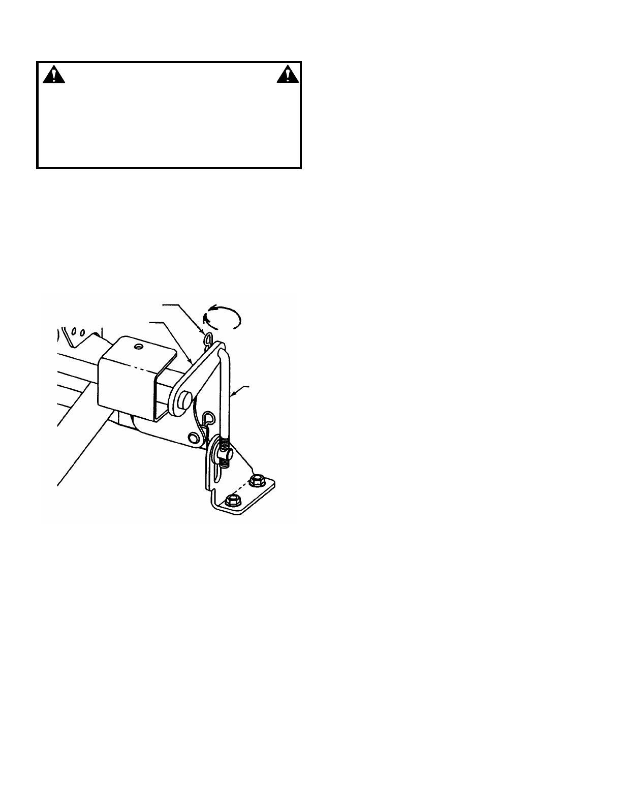
4.2.11. WHEEL BRAKE ADJUSTMENT
Adjust the wheel brake if wheels turn when parking
brake is engaged. Adjust the wheel brake by turning
wheel brake adjusting nut clockwise to increase
braking action or counter clockwise to decrease
braking action. See Figure 4.10.
FIGURE 4.10
X + 1/4”
X
FRONT
REAR
ROTATE HANGER PIVOT:
UP TO RAISE DECK OR
DOWN TO LOWER DECK.
ADJUSTING
NUT
DO NOT ADJUST
TIMING
ROD
42” DECK SHOWN
UNDERSIDE VIEW OF MACHINE
ELECTRIC
CLUTCH
WHEEL
BRAKE ROD
ADJUST
CLOCKWISE TO
INCREASE
BRAKE
ADJUST
COUNTER-
CLOCKWISE TO
DECREASE
BRAKE
/