Kenwood KAC-PS4D User manual
- Category
- Car audio amplifiers
- Type
- User manual
This manual is also suitable for

KAC-X4R
KAC-PS4D
FOUR CHANNEL DIGITAL POWER AMPLIFIER 7 page 2-11
INSTRUCTION MANUAL
AMPLIFICATEUR 4 CANAUX DIGITAL 7 page 12-21
MODE D’EMPLOI
AMPLIFICADOR DE POTENCIA DIGITAL DE CUATRO CANALES 7 página 22-31
MANUAL DE INSTRUCCIONES
© B64-3525-00/00 (KV/EV)
Take the time to read through this instruction manual. Familiarity
with installation and operation procedures will help you obtain the
best performance from your new power amplifier.
For your records
Record the serial number, found on the back of the unit, in the spaces
designated on the warranty card, and in the space provided below. Refer
to the model and serial numbers whenever you call upon your Kenwood
dealer for information or service on the product.
Model KAC-X4R/ KAC-PS4D Serial number
US Residence Only
Register Online
Register your Kenwood product at
www.kenwoodusa.com

2 English
Safety precautions
2WARNING
To prevent injury or fire, take the following precautions:
• Mounting and wiring this product requires skills and experience. For safety’s
sake, leave the mounting and wiring work to professionals.
• When extending the battery, or ground wires, make sure to use automotive-
grade wires or other wires with the range of 10 mm (AWG 8) to 25 mm (AWG
4) to prevent wire deterioration and damage to the wire coating.
• To prevent a short circuit, never put or leave any metallic objects (such as
coins or metal tools) inside the unit.
• If the unit starts to emit smoke or strange smells, turn off the power
immediately and consult your Kenwood dealer.
• Do not touch the unit during use because the surface of the unit becomes
hot and may cause burns if touched.
2CAUTION
To prevent damage to the machine, take the following
precautions:
• Be sure the unit is connected to a 12V DC power supply with a negative
ground connection.
• Do not open the top or bottom covers of the unit.
• Do not install the unit in a spot exposed to direct sunlight or excessive heat
or humidity. Also avoid places with too much dust or the possibility of water
splashing.
• When replacing a fuse, only use a new one with the prescribed rating. Using a
fuse with the wrong rating may cause your unit to malfunction.
• To prevent a short circuit when replacing a fuse, first disconnect the wiring
harness.
NOTE
• If you experience problems during installation, consult your Kenwood dealer.
• If the unit does not seem to be working right, consult your Kenwood dealer.
• Digital processing is performed inside this amplifier. Therefore, when used in
conjunction with other amplifiers, there may be a slight delay. If this occurs,
input the pre-output audio from this amplifier into the other amplifier.
FCC WARNING
This equipment may generate or use radio frequency energy. Changes or
modifications to this equipment may cause harmful interference unless the
modifications are expressly approved in the instruction manual. The user could
lose the authority to operate this equipment if an unauthorized change or
modification is made.
FCC NOTE
This equipment has been tested and found to comply with the limits for a
Class B digital device, pursuant to Part 15 of the FCC Rules. These limits are
designed to provide reasonable protection against harmful interference in
a residential installation. This equipment may cause harmful interference to
radio communications, if it is not installed and used in accordance with the
instructions. However, there is no guarantee that interference will not occur in a
particular installation. If this equipment does cause harmful interference to radio
or television reception, which can be determined by turning the equipment off
and on, the user is encouraged to try to correct the interference by one or more
of the following measures:
• Reorient or relocate the receiving antenna.
• Increase the separation between the equipment and receiver.
• Connect the equipment into an outlet on a circuit different from that to which
the receiver is connected.
• Consult the dealer or an experienced radio/TV technician for help.
NOTE
This Class B digital apparatus complies with Canadian ICES-003.
Information on Disposal of Old Electrical and Electronic
Equipment (applicable for EU countries that have adopted
separate waste collection systems)
Products with the symbol (crossed-out wheeled bin) cannot be
disposed as household waste.
Old electrical and electronic equipment should be recycled at a
facility capable of handling these items and their waste byproducts.
Contact your local authority for details in locating a recycle facility
nearest to you. Proper recycling and waste disposal will help conserve
resources whilst preventing detrimental effects on our health and the
environment.
This Product is not installed by the manufacturer of a vehicle on the production
line, nor by the professional importer of a vehicle into an EU Member State.
Cleaning the unit
If the front panel gets dirty, turn off the power and wipe the panel with a dry
silicon cloth or soft cloth.
2CAUTION
Do not wipe the panel with a hard cloth or a cloth dampened by volatile
solvents such as paint thinner and alcohol. They can scratch the surface of the
panel and/or cause the indicator letters to peel off.
To prevent battery rise
When the unit is used in the ACC ON position without turning the engine ON, it
depletes the battery. Use it after starting the engine.
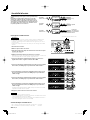
Protection function
There is a Protection function installed in the unit to protect the unit and
speakers from various problems. When Protection operates, the display informs
you of the condition.
Display Informations
"E-01" When the inside of the unit is overheating.
"E-02"
When the unit has failed and direct current voltage is generated to the speaker’s
output.
NOTE
Turn the power OFF and release the protection. If the "E-02" code does not disappear,
contact your Kenwood dealer.
"E-03"
When the speaker cord is shorted.
When the speaker output is in contact with the vehicle ground.
"E-99"
When a system error occurs.
Press the Reset button. If the "E-99" code does not disappear, contact your Kenwood
dealer.
"VOLT" display is
blinked.
When voltage gets out of operation range.
Wiring
• Take the battery wire for this unit directly from the battery. If it’s connected to
the vehicle’s wiring harness, it can cause blown fuses etc.
• If a buzzing noise is heard from the speakers when the engine is running,
connect a line noise filter (optional) to each of the battery wire.
• Do not allow the wire to directly contact the edge of the iron plate by using
Grommets.
• Connect the ground wire to a metal part of the car chassis that acts as an
electrical ground passing electricity to the battery‘s negative - terminal. Do
not turn the power on if the ground wire is not connected.
• Be sure to install a protective fuse in the power cord near the battery. The
protective fuse should be the same capacity as the unit’s fuse capacity or
somewhat larger.
• For the power cord and ground, use a vehicle type (fireproof) power wring
cord with a current capacity greater than the unit’s fuse capacity. (Use a power
wiring cord with a diameter between 10 mm (AWG 8) to 25 mm (AWG 4).)
• When more than one power amplifier are going to be used, use a power
supply wiring wire and protective fuse of greater current-handling capacity
than the total maximum current drawn by each amplifier.
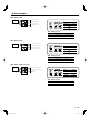
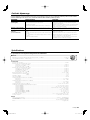
Speaker Selection
• The rated input power of the speakers that are going to be connected should
be greater than the maximum output power (in Watts) of the amplifier. Use of
speakers having input power ratings that are less than the output power of
the amplifier will cause smoke to be emitted as well as damage.
• The impedance of the speakers that are going to be connected should be 2
or greater (for stereo connections), or 4 or greater (for bridged connections).
When more than one set of speakers are going to be used, calculate the
combined impedance of the speakers and then connect suitable speakers to
the amplifier.
8 Ω
2 Ω
4Ω
4Ω 4Ω
4Ω
Combined impedance
4Ω4Ω
2Ω
8Ω
4Ω
4Ω

English 3
Installation
Accessories
Part name External View Number of Items
Self-tapping screws
(ø5 × 18 mm)
4
Hexagon Wrench (Large)
1
Hexagon Wrench (Small)
1
Test tone Disc
1
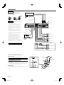
Installation procedure
Since there are large variety of settings and connections possible according to
applications, read the instruction manual well to select the proper setting and
connection.
1. Remove the ignition key and disconnect the negative - terminal of the
battery to prevent short circuits.
2. Set the unit according to the intended usage.
3. Connect the input and output wires of the units.
4. Connect the speaker wires.
5. Connect the power wire, power control wire and grounding wire following this
order.
6. Install the installation fittings in the unit.
7. Attach the unit.
8. Connect the negative - terminal of the battery.
2CAUTION
• Do not install in the below locations;
(Unstable location, In a location that interferes with driving, In a location
that gets wet, In a dusty location, In a place that gets hot, In a place that
gets direct sunlight, In a location that gets hit by hot air)
• Do not install the unit under the carpet. Otherwise heat build-up occurs
and the unit may be damaged.
• Install this unit in a location which allows heat to easily dissipate.
Once installed, do not place any object on top of the unit.
• The surface temperature of the amplifier will become hot during use. Install
the amplifier in a place where people, resins, and other substances that are
sensitive to heat will not come into contact with it.
• This unit has cooling fan to decrease the internal temperature. Do not
mount the unit in a place where the cooling fan and ducts of the unit are
blocked. Blocking these openings will inhibit the cooling of the internal
temperature and result in malfunction.
• When making a hole under a seat, inside the trunk, or somewhere else in
the vehicle, check that there is nothing hazardous on the opposite side
such as a gasoline tank, brake pipe, or wiring harness, and be careful not to
cause scratches or other damage.
• Do not install near the dashboard, rear tray, or air bag safety parts.
• The installation to the vehicle should securely fasten the unit to a place in
which it will not obstruct driving. If the unit comes off due to a shock and
hits a person or safety part, it may cause injury or an accident.
• After installing the unit, check to make sure that electrical equipment
such as the brake lamps, turn signal lamps and windshield wipers operate
normally.
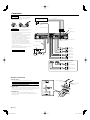
340 mm
279 mm
Ø6
194.5 mm
225 mm
Installation board, etc.
(thickness : 15 mm or more)
Self-tapping screw
(ø5 × 18 mm)
Hexagon socket
head cap screw
(M4 × 8 mm)
Hexagon Wrench
(Small)
Dressing cover
Self-tapping screw
(ø5 × 18 mm)
ø5 mm
ø7 – ø10 mm

4 English
2WARNING
To prevent fire caused by a short in the wiring,
connect a fusible link or breaker nearby the
battery’s positive terminal.
2CAUTION
• If sound is not output normally, immediately
turn power off and check connections.
• Be sure to turn the power off before changing
the setting of any switch.
• If the fuse blows, check wires for shorts, then
replace the fuse with one of the same rating.
• Check that no unconnected wires or
connectors are touching the car body. Do
not remove caps from unconnected wires or
connectors to prevent short circuits.
• Connect the speaker wires to appropriate
speaker connectors separately. Sharing the
negative wire of the speaker or grounding
speaker wires to the metal body of the car can
cause this unit to fail.
• After installation, check that the brake lamps,
winkers, and wipers work properly.
* Commercially available parts
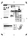
Connection
Ground wire*
Power control wire
Battery wire*
Protective Fuse*
CENTER UNIT
(CD receiver, etc.)
RCA cable*
Battery
7 – 10 mm
(9/32" – 3/8")
Hexagon Wrench
(Large)
About the Lead Terminals
1
Wire Thicknesses
You can use wires with the following thicknesses:
Battery wire and ground wire AWG 4 – AWG 8
Power control wire and speaker wire AWG 6 – AWG 18
2 Strip the wire
Make a cut in the wire sheath (insulator made from vinyl, etc.) at the
position 7-10 mm away from the end of the wire, and then remove
the unnecessary portion of the sheath by twisting it.
3 Install the wire
Loosen the screw using the supplied hexagon wrench.
Insert the conductor of the wire in the terminal hole, and then
tighten the screw.
Hexagon Wrench
(Small)
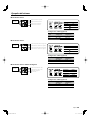
■ Bridged Connections
B channel
Speaker (Bridged)
A channel
Speaker (Bridged)
B channel
Right speaker
B channel
Left speaker
A channel
Right speaker
A channel
Left speaker
Left input
Right input
A channel input
B channel input

English 5
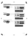
System examples
CENTER UNIT
■ 4-channel system
■ 2-channel system
CENTER UNIT
Right speaker (tweeter)
Left speaker (tweeter)
Front Right speaker
Front Left speaker
Rear Right speaker
Rear Left speaker
■ 2-channel + Subwoofer system
Subwoofer
(Bridged)
Right speaker (High pass)
Left speaker (High pass)
Switch Setting
INPUT SEL. AB
OPERATION
STEREO
OPERATION
STEREO
Channel Setting Item Setting value
A ch HPF > FREQ TH(through)
B ch HPF > FREQ TH(through)
Switch Setting
INPUT SEL. A
OPERATION
STEREO
OPERATION
STEREO
Switch Setting
INPUT SEL. AB
OPERATION
STEREO
OPERATION
STEREO
CENTER UNIT
Right speaker (woofer)
Left speaker (woofer)
• DSP Settings (page 8)
• DSP Settings (page 8)
• DSP Settings (page 8)
Channel Setting Item Setting value
A ch HPF > FREQ 150 Hz
B ch LPF > FREQ 150 Hz
Channel Setting Item Setting value
A ch HPF > FREQ 150 Hz
B ch LPF > FREQ 150 Hz

6 English
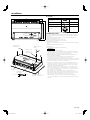
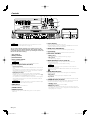
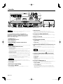
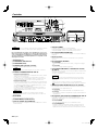
Controls
NOTE
The control panel locates under the dressing cover. Remove the cover to
access to its controls for adjustment. (See page 3)
This is a 4 channel amplifier including 2 stereo amplifiers in a body. One
amplifier is referred to as amplifier A and the other is amplifier B. This unit
is compatible with a large variety of systems by combining the switches and
functions described in the following.
1 Fuse (25 A × 3)
2 Battery terminal
3 Ground terminal
4 Power control terminal
Controls the unit ON/OFF.
NOTE
Controls the unit power. Be sure to connect it with all the systems.
5 Speaker output terminals (A.ch/B.ch)
• Stereo Connections:
When you wish to use the unit as a stereo amplifier, stereo connections are
used.
The speakers to be connected should have an impedance of 2 or greater.
When multiple speakers are to be connected, ensure that the combined
impedance is 2 or greater for each channel.
• Bridged Connections:
When you wish to use the unit as a high-output monaural amplifier,
bridged connections are used. (Make connections to the LEFT channel 9
and the RIGHT channel · SPEAKER OUTPUT terminals.)
The speakers to be connected should have an impedance of 4 or greater.
When multiple speakers are to be connected, ensure that the combined
impedance is 4 or greater.
2CAUTION
The rated input of the speakers should be no less than the maximum output
of the amplifier. Otherwise malfunction may result.
6 RESET button
Resets the microprocessor of the unit.
7 LINE IN terminal
8 LINE OUT terminal
Outputs the audio signal set in DSP settings (stereo or center speaker/
subwoofer).
9 Power indicator
Lights when the POWER switch is turned On.
The indicator flashes several seconds when the POWER switch is turned On
or when the Protection function is activated.
0 MODE switch (A/B/LINE OUT)
This switch selects the channel set in DSP settings (A, B, LINE OUT).
! Control knob
Allows you to switch between and determine Menu System items.
@ DISP switch (SET/INFO)
• INFO position:
Sets <Status Information Display and Settings> (page 7).
• SET position:
Sets <DSP Settings> (page 8).
# INPUT SENSITIVITY control (A.ch/B.ch)
Set this control according to the pre-output level of the center unit
connected with this unit.
See <Input Sensitivity> (page 10) for details on setting.
NOTE
• For the LINE OUT level, refer to the <Specifications> in the instruction
manual of the center unit.
• When A is selected with the INPUT SELECTOR switch, the control portion for
cannot be used.
$ INPUT SELECTOR switch
This switch selects the input method of the signals to be amplified by
amplifiers A and B.
• A B position:
Amplifies both of the signals input to amplifiers A and B.
• A position:
Amplifies only the signal input to amplifier A with both amplifiers A and B.
% OPERATION switch (A.ch/B.ch)
The amplification methods of the signals input to amplifiers A and B can be
selected independently according to the setting of this switch.
• STEREO position:
The amplifier can be used as a stereo amplifier.
• MONO (Lch) position:
Amplifies the signal input from the left side only. Set to this position and
make bridged connections to use as a high-power monaural amplifier. (The
input right signal is not output.)
96 78
!0
45321
%
@
#
$

English 7
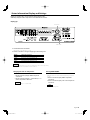
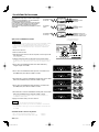
Status Information Display and Settings
Displays the operating voltage, current consumption and internal temperature.
Additionally, changes the units for temperature or turns ON/OFF the demonstration.
Display type
Control knob
DISP switch
1 Slide the DISP switch towards INFO.
“INFO” appears on the display for 1 second.
2 Turn the control knob to change the display type in the following order.
Display Information / Function
“VOLT” Displays the operating voltage (V).
“CURRT” Displays the current consumption (A).
“TEMP” Displays the internal temperature (°C / °F).
“DEMO” Sets demonstration display ON / OFF.
NOTE
• Temperatures lower than -22°F or -30°C are displayed as “-22F” or “-30C” respectively.
• Displayed information may differ from actual conditions.
Changing the units for temperature
Select °F (Fahrenheit) or °C (Celsius).
1 Turn the control knob, display “TEMP” and push the
control knob.
2 Turn the control knob, display “---F” (Fahrenheit) or “---C”
(Celsius) and push the control knob.
NOTE
The default setting is “---F” (Fahrenheit).
Turning DEMO ON/OFF
Turn the demonstration function ON to display “VOLT”, “CURRT” and
“TEMP” information. The demonstration display changes every five
seconds.
1 Turn the control knob, display “DEMO” and push the
control knob.
2 Turn the control knob, display “ON” or “OFF” and push the
control knob.
NOTE
The default setting is “OFF”.

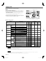
8 English
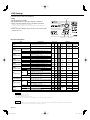
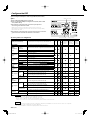
Item Setting value Ach Bch LINE OUT
LN.SEL ST / CT/SW (Default setting value : ST) × ×
ST
(When LN.SEL. is
set to “ST”)
CTR
(When LN.SEL. is
set to “CT/SW”)
SW
(When LN.SEL. is
set to “CT/SW”)
LEVEL -20 – 0 (Default setting value : 0) × ×
BAND1
(Parametric EQ-1)
FREQ (Hz)
(Mean frequency)
25/40/60/80/100 (Default setting value : 25)
×
Q 1.0/2.0/3.0/5.0 (Default setting value : 1.0)
GAIN -9 – +9 (Default setting value : 0)
BAND2
(Parametric EQ-2)
FREQ
150/200/300/400/500
(Default setting value : 150)
×
Q 1.0/2.0/3.0/5.0 (Default setting value : 1.0)
GAIN -9 – +9 (Default setting value : 0)
BAND3
(Parametric EQ-3)
FREQ 600/800/1k/1.5k/2k (Default setting value : 600)
×Q 1.0/2.0/3.0/5.0 (Default setting value : 1.0)
GAIN -9 – +9 (Default setting value : 0)
BAND4
(Parametric EQ-4)
FREQ 3k/4k/5k/6.3k (Default setting value : 3k)
×Q 2.0/4.0/8.0/10 (Default setting value : 2.0)
GAIN -9 – +9 (Default setting value : 0)
BAND5
(Parametric EQ-5)
FREQ 8k/10k/12.5k/16k (Default setting value : 8k)
×Q 2.0/4.0/8.0/10 (Default setting value : 2.0)
GAIN -9 – +9 (Default setting value : 0)
LPF
(Low Pass Filter)
FREQ
Low
TH/30/40/50/60/70/80/90/100/120/150/180/220/
250 (Default setting value : TH)
×
×
High
500/630/800/1k/1.25k/1.6k/2k/2.5k/3.15k/4k/5k
(Default setting value : TH)
×
×××
SLOPE −24/−12 (Default setting value : -12) × ×
ISF
(Infrasonic Filter)
FREQ
TH/20/30/40/50/60
(Default setting value : TH)
× ×××
HPF
(High Pass Filter)
FREQ
Low
TH/30/40/50/60/70/80/90/100/120/150/180/220/
250 (Default setting value : TH)
×
High
500/630/800/1k/1.25k/1.6k/2k/2.5k/3.15k/4k/5k
(Default setting value : TH)
× ×××
SLOPE −24/−12 (Default setting value : -12) ×
DELAY
L 0 – 3.9 (Default setting value : 0)
(L/R is not
differentiated)
×
R 0 – 3.9 (Default setting value : 0)
×
PHASE -180/0 (Default setting value : 0) ×
DSP Settings
Perform DSP settings for channels A, B and LINE OUT.
Setting
1 Slide the DISP switch towards SET.
2 Slide the MODE switch to set the channel (“Ach”, “Bch” or “LINE OUT”).
3 Turn the control knob, display the item to set and push the control knob.
Repeat this step until the item to set is displayed.
To return to the previous menu, turn the control knob, display “RTN” and press the
control knob.
4 Turn the control knob, display the value to set and press the control knob. The
displayed value is set.
Control knob
DISP switchMODE switch
Items and setting values
NOTE
• For LPF, HPF must be set to “TH”.
• For ISF, HPF must be set to “TH”.
• For HPF, LPF and ISF must be set to “TH”.
• If LPF and ISF are set simultaneously, LPF frequency cannot be lower than ISF frequency.
NOTE
• If speakers are bridged, set “L” and “R” for “DELAY” to the same value. Effects will not be applied properly if they are set to different values.
• DSP settings will not be cleared even when the reset button is pressed.

English 9
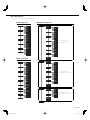
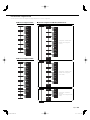
DSP settings menu list
See <Items and setting values> (page 8) for setting values.
BAND1 FREQ
Q
GAIN
RTN
FREQ
Q
GAIN
RTN
FREQ
GAIN
RTN
BAND2
BAND3
Q
FREQ
GAIN
RTN
Q
FREQ
GAIN
RTN
RTN
Q
BAND4
BAND5
HPF
LPF FREQ
SLOPE
RTN
RTN
FREQ
SLOPE
RTN
FREQISF
PHASE
DELAY L
R
BAND1 FREQ
Q
GAIN
RTN
FREQ
Q
GAIN
RTN
FREQ
GAIN
RTN
BAND2
BAND3
Q
FREQ
GAIN
RTN
Q
FREQ
GAIN
RTN
RTN
Q
BAND4
BAND5
HPF
LPF FREQ
SLOPE
RTN
RTN
FREQ
SLOPE
PHASE
LEVELST
CTR
SW
DELAY
FREQ
Q
GAIN
RTN
FREQ
GAIN
RTN
BAND2
BAND3
Q
FREQ
GAIN
RTN
Q
FREQ
GAIN
RTN
Q
BAND4
BAND5
HPF
RTN
RTN
FREQ
SLOPE
PHASE
LN.SEL
LEVEL
DELAY
FREQ
Q
GAIN
RTN
BAND1
LPF
RTN
RTN
FREQ
SLOPE
PHASE
LEVEL
DELAY
BAND1 FREQ
Q
GAIN
RTN
FREQ
Q
GAIN
RTN
FREQ
GAIN
RTN
BAND2
BAND3
Q
FREQ
GAIN
RTN
Q
FREQ
GAIN
RTN
Q
BAND4
BAND5
HPF
RTN
RTN
FREQ
SLOPE
DELAY L
R
Stereo output settings
(When LN.SEL is set to ST)
Center output settings
(When LN.SEL is set to CT/SW)
Subwoofer output settings
(When LN.SEL is set to CT/SW)
■ Ach setting menu ■ LINE OUT setting menu
■ Bch setting menu

10 English
This amplifier features a digital signal processor (DSP).
By processing signals digitally, finer equalization and filtering
are possible.
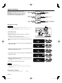
Input sensitivity is important to efficiently convert analog
signals to digital signals. If the input signal is too high, sound
is distorted. If it is too soft, sound quality deteriorates.
Input Sensitivity
High input
sensitivity
Optimum
sensitivity
Low input
sensitivity
Conversion
range
Over
Optimum
Conversion range
is not fully utilized
Conversion
range
Conversion
range
1 Disconnect the speakers.
2 Turn the audio system on.
3 Playback Track 2 in Test tone Disc with a CD receiver or other device.
Track 2 is 3 minutes long.
4 Set the device to the loudest volume you listen to.
For example, if this volume is approximately 80% of the maximum volume, the
volume is 30 on a device where volume can be set between 0 and 35.
5 Turn the input sensitivity control counterclockwise and set A.ch and B.ch to
MIN.
6 Turn the input sensitivity control for A.ch clockwise (towards MAX) until the
“OVER” indicator lights.
7 Slowly turn the input sensitivity control for A.ch counterclockwise (towards
MIN) until the “OVER” indicator turns off.
8 Turn the input sensitivity control for B.ch clockwise (towards MAX) until the
“OVER” indicator lights.
9 Slowly turn the input sensitivity control for B.ch counterclockwise (towards
MIN) until the “OVER” indicator turns off.
The setting where the “OVER” indicator turns off for A.ch and B.ch is the optimum
input sensitivity.
10 Turn the audio system off and connect the speakers.
NOTE
• To fine tune while listening to music
- If there is not enough volume: Turn the input sensitivity control clockwise
(towards MAX).
- If there is too much volume: Turn the input sensitivity control counterclockwise
(towards MIN).
Contents of the Test tone Disc
Track 1: Warning announcement (English and Japanese) 10 minutes
Track 2: Test tone (Sinusoidal-wave, 100 Hz, 0 dB) 3 minutes
Input sensitivity control
Adjusting input sensitivity
2CAUTION
• Be sure to disconnect speakers before adjusting input sensitivity.
• The test disc includes high volume test signals. Speakers may be damaged if input
sensitivity is adjusted while connected.
• Do not use the test disc for purposes other than adjusting input sensitivity.

English 11
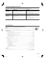
Troubleshooting Guide
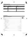
Specifications
Specifications subject to change without notice.
CEA-2006
RMS Watts per channel @ 4 ohms, 1 % THD+N .......................................................................................................................................................................100 W × 4
Signal to Noise Ratio (Reference: 1Watt into 4 ohms) ................................................................................................................................................................ 78 dBA
Audio Section
Max Power Output .........................................................................................................................................................................................................................................1200 W
Rated Power Output (+B = 12.0 V)
(4 ) (20 Hz – 20 kHz, 0.8 % THD) ....................................................................................................................................................................................... 75 W × 4
(2 ) (1 kHz, 1.0 % THD) ..........................................................................................................................................................................................................100 W × 4
(Bridged 4 ) (1 kHz, 1.0 % THD) ..................................................................................................................................................................................... 200 W × 2
Rated Power Output (+B = 14.4 V)
(4 ) (20 Hz – 20 kHz, 0.8 % THD) .....................................................................................................................................................................................100 W × 4
(4 ) (DIN45324, +B = 14.4 V) .............................................................................................................................................................................................100 W × 4
(2 ) (1 kHz, 1.0 % THD) ..........................................................................................................................................................................................................150 W × 4
(Bridged 4 ) (1 kHz, 1.0 % THD) .......................................................................................................................................................................................300 W × 2
Frequency Response (+0, -1 dB) ............................................................................................................................................................................................ 20 Hz – 20 kHz
Sensitivity (rated output) (MAX.) .................................................................................................................................................................................................................0.2 V
Sensitivity (rated output) (MIN.) ..................................................................................................................................................................................................................5.0 V
Input Impedance ...............................................................................................................................................................................................................................................10 k
Signal to Noise Ratio ......................................................................................................................................................................................................................................105 dB
Low Pass Filter Frequency (-24 / -12 dB/oct.)
Low Range .................................................................................................................................................................................................................................30 – 250 Hz
High Range ............................................................................................................................................................................................................................... 500 – 5k Hz
High Pass Filter Frequency (-24 / -12 dB/oct.)
Low Range .................................................................................................................................................................................................................................30 – 250 Hz
High Range ............................................................................................................................................................................................................................... 500 – 5k Hz
Infrasonic Filter Frequency (-24 dB/oct.) ........................................................................................................................................................20 / 30 / 40 / 50 / 60 Hz
Built in Parametric EQ Control
Frequency BAND 1 ...................................................................................................................................................................................25 / 40 / 60 / 80 / 100 Hz
Frequency BAND 2 ........................................................................................................................................................................150 / 200 / 300 / 400 / 500 Hz
Frequency BAND 3 ......................................................................................................................................................................... 600 / 800 / 1 k / 1.5 k / 2 k Hz
Frequency BAND 4 ........................................................................................................................................................................................3 k / 4 k / 5 k / 6.3 k Hz
Frequency BAND 5 ................................................................................................................................................................................8 k / 10 k / 12.5 k / 16 k Hz
Quality Factor BAND 1 – BAND3 ...................................................................................................................................................................... 1.0 / 2.0 / 3.0 / 5.0
Quality Factor BAND 4 – BAND5 ....................................................................................................................................................................... 2.0 / 4.0 / 8.0 / 10
Gain (Boost or Cut) ............................................................................................................................................................................................................-9 dB – +9 dB
Delay Control ........................................................................................................................................................................................................0 ms – 3.9 ms (0.1 ms Step)
Phase Inverter .....................................................................................................................................................................................................0° (Normal) / -180° (Reverse)
General
Operating Voltage ..............................................................................................................................................................................................14.4 V (11 – 16 V allowable)
Current Consumption ........................................................................................................................................................................................................................................60 A
Installation Size (W × H × D) .........................................................................................................................................................................................340 × 60 × 225 mm
..................................................................................................................................................................................................................1213-3/8 × 2-3/8 × 8-7/8 inch
Weight ...................................................................................................................................................................................................................................................3.8 kg (8.4 lbs)
Weight ..................................................................................................................................................................................................................................................................................
What might appear to be a malfunction in your unit may just be the result of slight misoperation or miswiring. Before calling service, first check the following
table for possible problems.
PROBLEM POSSIBLE CAUSE SOLUTION
No sound.
(Blown fuse.)
• Input (or output) cables are disconnected.
• Protection circuit may be activated.
• Volume is too high.
• The speaker cord is shorted.
• Connect the input (or output) cables.
• Check connections by referring to <Protection function>.
• Replace the fuse and use lower volume.
• After check the speaker cord and fixing the cause of the short,
replace the fuse.
The output level is too small
(or too large).
• The input sensitivity adjusting control is not set to the correct
position.
• Adjust the control correctly referring to <Input Sensitivity>.
The sound quality is bad.
(The sound is distorted.)
• The speakers wire are connected with wrong + /-polarity.
• A speaker wire is pinched by a screw in the car body.
• The switches may be set improperly.
• The “OVER” indicator is lit.
• Connect them properly checking the + / - of the terminals
and wires well.
• Connect the speaker wire again so that it is not pinched by
anything.
• Set switches properly by referring to <Controls> or <DSP
Settings>.
• Input level is too high. See <Input Sensitivity> and adjust.
Page is loading ...
Page is loading ...
Page is loading ...
Page is loading ...
Page is loading ...
Page is loading ...
Page is loading ...
Page is loading ...
Page is loading ...
Page is loading ...
Page is loading ...
Page is loading ...
Page is loading ...
Page is loading ...
Page is loading ...
Page is loading ...
Page is loading ...
Page is loading ...
Page is loading ...
Page is loading ...
Page is loading ...
-
 1
1
-
 2
2
-
 3
3
-
 4
4
-
 5
5
-
 6
6
-
 7
7
-
 8
8
-
 9
9
-
 10
10
-
 11
11
-
 12
12
-
 13
13
-
 14
14
-
 15
15
-
 16
16
-
 17
17
-
 18
18
-
 19
19
-
 20
20
-
 21
21
-
 22
22
-
 23
23
-
 24
24
-
 25
25
-
 26
26
-
 27
27
-
 28
28
-
 29
29
-
 30
30
-
 31
31
-
 32
32


Kenwood KAC-PS4D User manual
- Category
- Car audio amplifiers
- Type
- User manual
- This manual is also suitable for
Ask a question and I''ll find the answer in the document
Finding information in a document is now easier with AI
in other languages
- français: Kenwood KAC-PS4D Manuel utilisateur
- español: Kenwood KAC-PS4D Manual de usuario