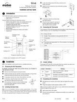
Installation Guide
4
ENGLISH
NOTE: This setting is necessary only if the thermostat is connected to a heat pump.
The jumper is located on the back of the thermostat faceplate. Set it according to the type
of reversing (changeover) valve used by the heat pump.
• O (factory setting): The reversing valve is energized when the System switch is set to
Cool (cooling mode).
• B: The reversing valve is energized when the System switch is set to Heat (heating
mode).
Incorrect jumper setting: The heat pump operation will be reversed; i.e., it will cool in
Heat mode and will heat in Cool mode.
NOTE: This setting is not applicable if a fan is not connected to the G terminal.
A jumper, located on the back of the thermostat faceplate, determines how the fan operates
in Automatic mode. This jumper is not available on TH1100, TH1210D and TH2210D. On
these models, when the fan is placed in Automatic mode, it starts right away when there is
a call for heat or cool.
• HG (factory setting): Leave the jumper in this position for gas or oil heating systems. In this
position, the heating system controls the fan operation. When there is a call for heat, the fan
starts only when the air coming out of the vents is sufficiently warm. When there is a call for
cool, the fan starts right away.
• HE: Place the jumper to this position for heat pump or electric heating systems. In this
position, the thermostat activates the fan as soon as there is a call for heat or cool.
Incorrect jumper setting: An incorrect setting is noticeable in a gas or oil heating system.
When heating starts, you will initially feel cold air coming out of the vents as the fan is
running before the furnace has enough time to heat up the air.
If a 24-VAC common wire is connected to the C terminal, batteries are
optional and serve to provide backup power.
If a 24-VAC common wire is not connected to the C terminal, batteries
are necessary to power the thermostat.
Install 2 AAA batteries on the back of the thermostat faceplate as
shown.
n Align the two brackets on the top of the thermostat with the
corresponding slots on the top of the wallplate.
o Push the faceplate against the wallplate.
p Tighten the screw at the bottom of the thermostat.
Reversing valve setting
Fan operation setting
Battery installation
Thermostat mounting
400-626-000-D (69-1968EFS-03 TH1000D_TH2000D installation manual).book Page 4 Thursday, April 16, 2009 3:31 PM


