Page is loading ...

311797J
Repair
GH
™
130, GH 200,
GH 230, GH 300
Hydraulic Sprayers
- Use with Architectural Coatings and Paints -
3300 psi (2.8 MPa, 228 bar) Maximum Working Pressure
List of models provided on page 2.
IMPORTANT SAFETY INSTRUCTIONS.
Read all warnings and instructions in this manual. Save these instructions. Contact
Graco Customer Service, your local Graco distributor or our website:
www.graco.com, to obtain a manual in your language.
ti5380a
ENG

Models
2 311797J
Models
Electric Motor Kit Options
253957
✔✔
253959
✔✔✔
253980
✔✔✔
253962
✔✔
253963
✔✔✔
253981
✔✔✔
255095
✔✔
253965
✔✔
253966
✔✔ ✔
253982
✔✔✔
253968
✔✔
GH130 GH200 GH230 GH300
120 Vac
60 Hz
ETL/CSA/UL
120 Vac
60 Hz
Kit Number Sprayer Model Description
288474
GH130 120VAC, 60Hz, 20A, CAS/UL approved
288473
GH130 120VAC, 60Hz, 15A
248950
GH200/GH230 120VAC, 60Hz, 20A, CSA/UL approved
248949
GH200/GH230 120 VAC, 60Hz, 15A
248946
EH200/HD1200 240VAC, 50Hz, 13.4A

Models
311797J 3
Warnings
The following Warnings are for the setup, use, grounding, maintenance and repair of this equipment. The exclama-
tion point symbol alerts you to a general warning and the hazard symbols refer to procedure-specific risks. Refer
back to these Warnings. Additional, product-specific warnings may be found throughout the body of this manual
where applicable.
WARNINGWARNINGWARNING
WARNING
FIRE AND EXPLOSION HAZARD
Flammable fumes, such as solvent and paint fumes, in work area can ignite or explode. To help prevent
fire and explosion:
• Use equipment only in well ventilated area.
• Eliminate all ignition sources; such as pilot lights, cigarettes, portable electric lamps, and plastic drop
cloths (potential static arc).
• Keep work area free of debris, including solvent, rags and gasoline.
• Do not plug or unplug power cords, or turn power or light switches on or off when flammable fumes are
present.
• Ground all equipment in the work area. See Grounding instructions.
• Use only grounded hoses.
• Hold gun firmly to side of grounded pail when triggering into pail.
• If there is static sparking or you feel a shock, stop operation immediately. Do not use equipment until
you identify and correct the problem.
• Keep a working fire extinguisher in the work area.
SKIN INJECTION HAZARD
High-pressure fluid from gun, hose leaks, or ruptured components will pierce skin. This may look like just
a cut, but it is a serious injury that can result in amputation. Get immediate surgical treatment.
• Do not point gun at anyone or at any part of the body.
• Do not put your hand over the spray tip.
• Do not stop or deflect leaks with your hand, body, glove, or rag.
• Do not spray without tip guard and trigger guard installed.
• Engage trigger lock when not spraying.
• Follow Pressure Relief Procedure in this manual, when you stop spraying and before cleaning,
checking, or servicing equipment.
ELECTRIC SHOCK HAZARD
Improper grounding, setup, or usage of the system can cause electric shock.
• Turn off and disconnect power cord before servicing equipment.
• Use only grounded electrical outlets.
• Use only 3-wire extension cords.
• Ensure ground prongs are intact on sprayer and extension cords.
• Do not expose to rain. Store indoors.

Models
4 311797J
MOVING PARTS HAZARD
Moving parts can pinch or amputate fingers and other body parts.
• Keep clear of moving parts.
• Do not operate equipment with protective guards or covers removed.
• Pressurized equipment can start without warning. Before checking, moving, or servicing equipment,
follow the Pressure Relief Procedure in this manual. Disconnect power or air supply.
PRESSURIZED ALUMINUM PARTS HAZARD
Do not use 1,1,1-trichloroethane, methylene chloride, other halogenated hydrocarbon solvents or fluids
containing such solvents in pressurized aluminum equipment. Such use can cause serious chemical
reaction and equipment rupture, and result in death, serious injury, and property damage.
SUCTION HAZARD
Never place hands near the pump fluid inlet when pump is operating or pressurized. Powerful suction
could cause serious injury.
CARBON MONOXIDE HAZARD
Exhaust contains poisonous carbon monoxide, which is colorless and odorless. Breathing carbon
monoxide can cause death. Do not operate in an enclosed area.
TOXIC FLUID OR FUMES HAZARD
Toxic fluids or fumes can cause serious injury or death if splashed in the eyes or on skin, inhaled, or
swallowed.
• Read MSDS’s to know the specific hazards of the fluids you are using.
• Store hazardous fluid in approved containers, and dispose of it according to applicable guidelines.
BURN HAZARD
Equipment surfaces and fluid that’s heated can become very hot during operation. To avoid severe burns,
do not touch hot fluid or equipment. Wait until equipment/fluid has cooled completely.
PERSONAL PROTECTIVE EQUIPMENT
You must wear appropriate protective equipment when operating, servicing, or when in the operating area
of the equipment to help protect you from serious injury, including eye injury, inhalation of toxic fumes,
burns, and hearing loss. This equipment includes but is not limited to:
• Protective eyewear
• Clothing and respirator as recommended by the fluid and solvent manufacturer
•Gloves
• Hearing protection
WARNINGWARNINGWARNING
WARNING

Component Identification
311797J 5
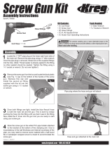
Component Identification
3.
4.
5.
7.
6.
8.
OFF
ON
2.
bar/MPa
PSI
on
off
1.
10.
11.12.
ti8714a
ti9126a
ti8844a
ti8691a
9.
ti9167a
ti9166a
ti5381b
13.
Item No. Component
1 Hydraulic pump valve
2 Pressure control
3 Hydraulic Oil Cap
4Drain valve
5 Engine ON/OFF switch
6 Engine controls
7 Electric motor On/Off Switch
8 Gun trigger Lock
9 Displacement pump
10
ProConnect
™
11 Inlet strainer (standard)
12 Inlet strainer (option)
13 Serial number tag

General Repair Information
6 311797J
General Repair Information
1 Keep all screws, nuts, washers, gaskets, and electrical
fittings removed during repair procedures. These parts
are not normally provided with replacement assemblies.
2 Test repair after problem is corrected.
3 If sprayer does not operate properly, review repair
procedure to verify procedure was done correctly. If
necessary, see Troubleshooting Guide, page 7, for other
possible solutions.
4 Install belt guard before operation of sprayer and replace
if damaged. Belt guard reduces risk of pinching and loss
of fingers; see preceding WARNING.
Grounding
Ground sprayer with grounding clamp to earth ground
for safe sprayer operation when using solvent-based
materials. Fig. 1.
F
IG. 1
SAE O-Ring Installation
1 Unscrew lock nut to touch fitting.
2 Lubricate o-ring (A).
3 Screw in fitting hand tight.
4 Unscrew fitting until oriented
properly.
5 Tighten lock nut to indicated torque.
(Make sure washer is seated properly
without pinching o-ring).
To reduce risk of serious injury, do not touch moving
parts with fingers or tools while testing repair. Shut
off sprayer when repairing. Install all covers,
gaskets, screws and washers before operating
sprayer
6250
A
ti5414a
ti5415a
ti5416a
ti5417a

Maintenance
311797J 7
Maintenance
Pressure Relief Procedure
The system pressure must be manually relieved to
prevent the system from starting or spraying
accidentally. Fluid under high pressure can be injected
through the skin and cause serious injury. To reduce
the risk of an injury from injection, splashing fluid, or
moving parts, follow the Pressure Relief Procedure
whenever you:
• are instructed to relieve the pressure,
• stop spraying,
• check or service any of the system equipment,
• or install or clean the spray tip.
1 Lock gun trigger safety.
2 Turn engine ON/OFF switch to OFF.
3 Move pump valve to OFF (down) and turn pressure
control knob fully counter clockwise.
4 Unlock trigger safety. Hold metal part of gun firmly to side
of grounded metal pail, and trigger gun to relieve
pressure.
5 Lock gun trigger safety.
6 Open pressure drain valve. Leave valve open until ready
to spray again.
If you suspect that the spray tip or hose is completely
clogged, or that pressure has not been fully relieved
after following the steps above, VERY SLOWLY loosen
tip guard retaining nut or hose end coupling to relieve
pressure gradually, then loosen completely. Now clear
tip or hose.
DAILY: Check engine oil level and fill as necessary.
DAILY: Check hydraulic oil level and fill as necessary.
DAILY: Check hose for wear and damage.
DAILY: Check gun safety for proper operation.
DAILY: Check pressure drain valve for proper operation.
DAILY: Check and fill the gas tank.
DAILY: Check that displacement pump is tight.
DAILY: Check level of Throat Seal Liquid (TSL) in dis-
placement pump packing nut. Fill nut, if necessary. Keep
TSL in nut to help prevent fluid buildup on piston rod and
premature wear of packings and pump corrosion.
AFTER THE FIRST 20 HOURS OF OPERATION:
Drain engine oil and refill with clean oil. Reference
Honda Engines Owner's Manual for correct oil viscosity.
WEEKLY: Remove engine air filter cover and clean ele-
ment. Replace element, if necessary. If operating in an
unusually dusty environment: check filter daily and
replace, if necessary.
Replacement elements can be purchased from your
local HONDA dealer.
WEEKLY/DAILY: Remove any debris or media from
hydraulic rod.
AFTER EACH 100 HOURS OF OPERATION:
Change engine oil. Reference Honda Engines Owner's
Manual for correct oil viscosity.
SEMI-ANNUALLY:
Check belt wear, page 10; replace if necessary.
YEARLY OR 2000 HOURS:
Replace hydraulic oil and filter with Graco hydraulic oil
169236 (5 gallon/20 liter) or 207428 (1 gallon/3.8 liter)
and filter 116909.
Replace belt.
SPARK PLUG: Use only BPR6ES (NGK) or W20EPR-U
(NIPPONDENSO) plug. Gap plug to 0.028 to 0.031 in.
(0.7 to 0.8 mm). Use spark plug wrench when installing
and removing plug.
NOTICE
For detailed engine maintenance and specifications,
refer to separate Honda Engines Owner's Manual,
supplied.

Troubleshooting
8 311797J
Troubleshooting
PROBLEM CAUSE SOLUTION
Gas engine pulls hard (won't start) Hydraulic pressure is too high Turn hydraulic pressure knob counter
clockwise to lowest setting.
Gas engine does not start Switch OFF, low oil, no gasoline Consult engine manual, supplied.
Gas engine doesn't work properly Faulty engine Consult engine manual, supplied.
Elevation Refer to Engine Repair Kit.
4.0 hp - 288678 / 5.5 hp - 248943 /
6/5 hp - 248944 / 9.0 hp - 248945
Gas engine operates, but displacement
pump doesn't operate
Hydraulic pump valve is OFF Set hydraulic pump valve ON.
Pressure setting too low Increase pressure.
Displacement pump outlet filter (if used)
is dirty or clogged
Clean the filter.
Tip or tip filter (if used) is clogged Remove tip and/or filter and clean.
Hydraulic fluid too low Shut off sprayer. Add fluid*.
Belt worn or broken or off Replace, page 12.
Hydraulic pump worn or damaged Bring sprayer to Graco distributor for repair.
Dried paint seized paint pump rod Service pump. See manual 311845.
Hydraulic motor not shifting Set pump valve OFF. Turn pressure down.
Turn engine OFF. Pry rod up or down until
hydraulic motor shifts .
Displacement pump operates, but output
is low on upstroke
Piston ball check not seating properly Service piston ball check. See manual
311845.
Piston packings worn or damaged Replace packings. See manual 311845.
Displacement pump operates but output
is low on downstroke and/or on both
strokes
Piston packings worn or damaged Tighten packing nut or replace packings.
See manual 311845.
Intake valve ball check not seating
properly
Service intake valve ball check. See man-
ual 311845.
Suction tube air leak
Paint leaks and runs over side of wetcup Loosen wet-cup Tighten wet-cup enough to stop leakage.
Throat packings worn or damaged Replace packings. See manual 311845.
Excessive leakage around hydraulic
motor piston rod wiper
Piston rod seal worn or damaged Replace these parts.
Fluid delivery is low Pressure setting too low Increase pressure.
Displacement pump outlet filter (if used)
is dirty or clogged
Clean filter.
Intake line to pump inlet is not tight Tighten.
Hydraulic motor is worn or damaged Bring sprayer to Graco distributor for repair.
Large pressure drop in fluid hose Use larger diameter or shorter hose.
The sprayer overheats Paint buildup on hydraulic components Clean.
Spitting from gun Air in fluid pump or hose Check for loose connections on siphon
assembly, tighten, then reprime pump.
Loose intake suction Tighten.
Fluid supply is low or empty Refill supply container.
Excessive hydraulic pump noise Low hydraulic fluid level Turn sprayer OFF. Add fluid*.
Electric motor does not operate Power switch is not ON Turn power switch to ON.
Tripped circuit breaker Check circuit breaker at power source.
Reset motor switch.
*Check hydraulic fluid level often. Do not allow it to become too low. Use only Graco approved hydraulic fluid.

Notes
311797J 9
Notes

Hydraulic Pump
10 311797J
Hydraulic Pump
(Figure 2)
Removal
Let hydraulic system cool before beginning service.
1 Relieve pressure, page 7.
2 Place drip pan or rags under sprayer to catch hydraulic oil
that leaks out during repair.
3 Remove drain plug (2) and oil filter (227) and allow
hydraulic oil to drain.
4 Fig. 2. Disconnect suction tube (114).
5 Disconnect pump (111), page 15.
6 Remove screw (172), nut (173) and belt guard (117).
7 Raise motor and remove belt (44).
8 Remove two set screws (176) and fan pulley (96).
9 Remove case drain tube (225).
10 Remove elbow (221).
11 Remove tube (276) from elbow (226). Remove elbow
(226) from hydraulic pump (220).
12 Remove eight screws (212) reservoir cover (209) filter
assembly (206) and gasket (203).
13 Remove four screws (277) and hydraulic pump (220) from
reservoir cover (209).
Installation
1 Install hydraulic pump (220) to reservoir cover (209) with
four screws (277); torque 90-110 in-lb (10.1-12.4 N·m).
2 Install gasket (203) and reservoir cover (209) with eight
screws (212); torque 110+/-5 in-lb (12.4 +/- 0.5 N·m).
3 Install elbow (226) in hydraulic pump (220). Install elbow
(226) in tube (276). Torque to 25 ft-lb (33.9 N·m).
4 Install elbow (221); torque to 15 ft-lb (20.3 N·m).
5 Install case drain tube (225); torque to 15 ft-lb (20.3 N·m).
6 Install fan pulley (96) with two set screws (176).
7 Raise motor and install belt (44).
8 Install belt guard (117) with screw (172) and nut (173).
9 Connect pump (111), page 15.
10 Fig. 2. Connect suction tube (114).
11 Install drain plug (2); torque to 110 in-lb (12.4 N·m). Install
oil filter (227); tighten 3/4 turn after gasket contacts base.
Fill hydraulic pump with Graco hydraulic oil, page 6,
through elbow (221) port until full. Fill reservoir with
remaining hydraulic oil.
12 Start up and allow pump to operate at low pressure for
approximately 5 minutes to purge all air.
13 Check oil hydraulic oil and top off, if required.

Hydraulic Pump
311797J 11
FIG. 2
172
117
173
176
96 44
114
111
277
212
209
227
222
225
211
220
276
266
203
206
2
ti8821b
221
226
207

Fan Belt
12 311797J
Fan Belt
(Figure 3)
Removal
1 Relieve pressure, page 7.
2 Loosen belt guard knob (55).
3 Rotate belt guard (117) up.
4 Lift engine (119) up to remove tension on belt (44).
5 Remove belt from pulley (43) and fan pulley (96).
Installation
1 Thread belt (44) around drive pulley (43) and fan pulley
(96).
2 Let engine (119) down to put tension on belt.
3 Rotate belt guard (117) down.
4 Tighten belt guard knob (55).
FIG. 3
55
43
119
44
117
96
ti8814a
ti8816a
ti8815a

Engine
311797J 13
Engine
(Figure 4)
Removal
NOTE: All service to the engine must be performed by
an authorized HONDA dealer.
1 Relieve pressure, page 7.
2Remove Fan Belt, page 10.
3 Loosen motor nut (205). Swing motor retainer bracket
(204) out.
4 Remove engine (119) and rocker plate (99) from sprayer.
5 Remove four screws (23), washers (7) and nuts (24) and
remove rocker plate (99), dampeners (153) and washers
(154) from engine (119).
Installation
1 Install rocker plate (99), dampeners (153) and washers
(154) on engine (119) with four screws (23), washers (7)
and nuts (24); torque to 125 in-lb (14.1 N·m).
2 Install engine and rocker plate (99) on sprayer.
3 Swing motor retainer bracket (204) in. Tighten motor nut
(205).
4 Install Fan Belt, page 10.
FIG. 4
TIA

Hydraulic Motor Rebuild
14 311797J
Hydraulic Motor Rebuild
(Figure 5)
Removal
1 Relieve pressure, page 7.
2 Place drip pan or rags under sprayer to catch hydraulic oil
that leaks out during repair.
3 GH130 Models:
- Follow Steps 2-5 of pump removal instructions, page 17.
GH200, GH230, GH300 Models:
- Follow Steps 4-8 of pump removal instructions, page 18.
4 Remove hydraulic lines (271, 288) from fittings (266) at
top left and right side of hydraulic motor.
5 Loosen jam nut (264).
6 Unscrew and remove hydraulic motor cap (265).
7 Slide piston rod/hydraulic motor cap assembly (A) from
hydraulic motor cylinder (263).
Installation
1 Slide piston rod assembly into hydraulic motor
cylinder (263).
2 Screw down hydraulic motor cap (265). Unscrew hydraulic
motor cap until inlet and outlet align with hydraulic line
fittings and test hole in hydraulic motor cap points toward
belt guard (117).
3 Torque jam nut (264) against hydraulic motor cap (265) to
150 ft-lb (17 N•m).
4 Fig. 5. Install hydraulic lines (271, 288) to fittings (266) to
top left and right side of hydraulic motor; torque to 40 ft-lb
(54.2 N•m).
5 GH130 Models:
- Follow Step 2 of pump installation instructions, page 17.
GH200, GH230, GH300 Models:
- Follow Steps 2-7 of pump installation instructions, page
19.
6 Start engine and operate pump for 30 seconds. Turn
engine OFF. Check hydraulic oil level and fill with Graco
hydraulic oil, page 6.
FLYING PARTS HAZARD
Detent spring has high energy potential. If detent
spring is released without due care detent spring
and balls could fly into the eyes of the disassembler.
Wear safety glasses when removing or installing
detent spring and balls. Failure to wear safety
glasses when removing detent spring could result in
eye injury or blindness.
FLYING PARTS HAZARD

311797J 15
FIG. 5
ti8817a
ti8818a
271
test hole
266
288
265
264
263
A

Hydraulic Oil/Filter Change
16 311797J
Hydraulic Oil/Filter Change
(Figure 6)
Removal
1 Relieve pressure, page 7.
2 Place drip pan or rags under sprayer to catch hydraulic oil
that drains out.
3 Remove drain plug (2). page 26. Allow hydraulic oil to
drain.
4 Unscrew filter (227) slowly - oil runs into groove and
drains out rear.
Installation
1 Install drain plug (2) and oil filter (227). Tighten oil filter 3/4
turn after gasket contacts base.
2 Fill with five quarts of Graco hydraulic oil 169236 (5
gallon/20 liter) or 207428 (1 gallon/3.8 liter).
3 Check oil level.
FIG. 6
TIA

Displacement Pump
311797J 17
Displacement Pump
GH130 Only
(Figures 7-12)
See manual 311845 for pump repair instructions
Removal
1 Flush pump.
2 Relieve pressure, page 7.
3 (Fig. 7) Remove suction tube (114) and paint hose (63)
(remove at swivel end).
FIG. 7
4 (Fig. 8) Push retaining ring (120) up; push out pin (92).
FIG. 8
5 (Fig. 9). Loosen jam nut (86). Unscrew pump (111).
FIG. 9
Installation
1 (Fig 10) Screw jam nut (86) to bottom of pump (111)
threads. Screw pump (111) completely into manifold.
Unscrew pump (111) from manifold until pump outlet
aligns with hose. Hand tighten jam nut (86), then tap 1/8
to 1/4 turn with hammer or torque to 75 ft-lb (101 N·m).
FIG. 10
2 (Fig. 11) Slowly pull engine starter rope until pump rod pin
hole is aligned with hydraulic rod hole. Fig. 8. Push pin
(92) into hole. Push retaining ring (120) into groove.
FIG. 11
3 (Fig. 12) Fill packing nut with Graco TSL.
ti2272a
114
63
TIB
92
120
ti2272c
86
If pin (92) works loose, parts could break off and project
through the air, resulting in serious injury or property
damage. Make sure pin is properly installed.
CAUTION
If the pump jam nut (86) loosens during operation, the
threads of the bearing housing and drive train will be dam-
aged. Tighten jam nut (86) as specified.
ti2272d
86
111
TIE
120
92
ti2272f

Displacement Pump ProConnect
18 311797J
Displacement Pump ProConnect
GH200/230/300 Only
(Figures 13-27)
See pump manual 311845 for pump repair.
Removal
1 Flush pump.
2 Relieve pressure, page 7.
3 (Fig. 13) Remove suction hose (114).
FIG. 12
4 (Fig. 14) Remove paint hose fitting (190) and paint hose
(63) from pump fitting.
FIG. 13
5 (Fig. 15) Slide coupler cover (193) up to fully expose rod
couplers (179).
FIG. 14
6 (Fig. 16) Remove rod couplers (179).
FIG. 15
7 (Fig 17) Remove pin.
FIG. 16
ti8827a
ti8828a
190
63
ti8829a
193
179
ti8830a
179
179
ti8831a

Displacement Pump ProConnect
311797J 19
8 (Fig. 18) Open clamp (247).
FIG. 17
9 (Fig. 19) Remove pump (111) from unit.
FIG. 18
Installation
1 (Fig. 20) If needed, place pump rod in adjustment casting
and pull pump to lengthen rod.
FIG. 19
2 (Fig. 21) Install pump (111) in sprayer.
FIG. 20
3 (Fig. 22) Close clamp (247) around pump (111) and push
it closed.
FIG. 21
NOTE: Closing force on T-handle can be adjusted if needed by
inserting pin into adjustment hole and turning.
CAUTION
Support pump with your hand before opening t-handle.
ti8833a
ti8832a
111
ti8834a
111
ti8959a
24
7
ti8958a
Adjustment hole

Displacement Pump ProConnect
20 311797J
4 (Fig. 23) Install pin.
FIG. 22
5 (Fig. 24) Slide coupler cover (193) up to expose pump
rod. Install rod couplers (179) over rod.
FIG. 23
6 (Fig. 25) Slide couple cover (193) down over rod couplers
(179).
FIG. 24
7 (Fig. 26) Open clamp and align pump outlet with hose
fitting (190). Install paint hose fitting (190) and paint hose
(63) to pump connection, close clamp.
FIG. 25
8 (Fig. 27) Install suction hose (114) to bottom of pump
(111).
FIG. 26
ti8957a
193
179
179
ti8956a
193
179
ti8955a
190
63
ti8954a
111
114
ti8953a
/