Kenwood TK-5720 User manual
- Category
- Car media receivers
- Type
- User manual
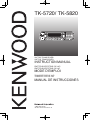
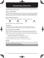
Kenwood TK-5720 is a full-featured VHF P25 transceiver that offers a wide range of capabilities for both professional and personal use. With its rugged construction and advanced features, the TK-5720 is ideal for use in a variety of applications, including public safety, security, and business.
some of the key features of the TK-5720 include:
- P25 compliance: The TK-5720 is compliant with the P25 digital radio standard, which provides clear and reliable communications in both noisy and weak signal environments.
- Dual-band operation: The TK-5720 can operate on both the VHF and UHF frequency bands, giving you the flexibility to communicate with a wide range of devices.


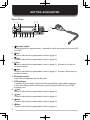
-
 1
1
-
 2
2
-
 3
3
-
 4
4
-
 5
5
-
 6
6
-
 7
7
-
 8
8
-
 9
9
-
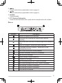 10
10
-
 11
11
-
 12
12
-
 13
13
-
 14
14
-
 15
15
-
 16
16
-
 17
17
-
 18
18
-
 19
19
-
 20
20
-
 21
21
-
 22
22
-
 23
23
-
 24
24
-
 25
25
-
 26
26
-
 27
27
-
 28
28


Kenwood TK-5720 User manual
- Category
- Car media receivers
- Type
- User manual
Kenwood TK-5720 is a full-featured VHF P25 transceiver that offers a wide range of capabilities for both professional and personal use. With its rugged construction and advanced features, the TK-5720 is ideal for use in a variety of applications, including public safety, security, and business.
some of the key features of the TK-5720 include:
- P25 compliance: The TK-5720 is compliant with the P25 digital radio standard, which provides clear and reliable communications in both noisy and weak signal environments.
- Dual-band operation: The TK-5720 can operate on both the VHF and UHF frequency bands, giving you the flexibility to communicate with a wide range of devices.
Ask a question and I''ll find the answer in the document
Finding information in a document is now easier with AI
Related papers
Other documents
-
GME TX4800 User manual
-
Midland STM-1115B Owner's manual
-
 AirTech ONKATS-400B User manual
-
Vertex Standard VX-2200 User manual
-
Midland Radio MMA901115 User manual
-
ICOM VE-PG4 Operating instructions
-
ICOM iF9511HT User manual
-
-
Vertex VX-1700 Operating instructions
-
