Page is loading ...

A/V DISTRIBUTION & CONTROL SYSTEMS
SP503.1 SP523.1
SP522.1
Instruction Manual

2
INTRODUCTIONS
Congratulations on selecting Russound Ceiling-Mounted Speakers. Like
all RUSSOUND speakers, they combine acoustic technology with durabil-
ity and will provide years of musical enjoyment. An added feature of
model SP503.1 and model SP522.1 is the dual-voice coil design. This is
unique in that both left and right signals can function in one speaker,
which is ideal for installations in bathrooms, laundry rooms, hallways,
etc.
This manual is intended to make your SP503.1, SP522.1 or SP523.1
speakers as easy to install as they are to listen to. If you’ve had any
home “do-it-yourself” experience, you should find installation of your
new speakers a simple job.
However, we suggest you read through this manual before starting
out. If you then decide that installing your Russound In-Wall
Speakers is beyond your skills, call your Russound dealer to arrange
for professional installation.
NECESSARY TOOLS TO DO THE JOB
TOOLS FOR INSTALLATION IN EXISTING WALLS
• A pencil
• A drill with a 1-inch flat bit
• A retractable utility knife or keyhole saw
• A length of stiff wire about 3 feet long (a straightened wire coat
hanger works fine)
• A Phillips-head screw driver which will fit the fastening-screws (for
the dog ears)
• A pair of diagonal pliers or wire strippers
Some of the following may also be needed, depending on the
application:
• A stud finder
• A Drill bit just slightly larger than the diameter of one speaker wire
• Insulated staples for securing speaker wire
• Masking tape
• Paint and applicator for changing grille and outer frame finish
SPEAKER WIRE
The amount of wire you’re going to need will of course vary with speak-
er placement. We recommend labeling speaker wires left + right and
room location. Doing this takes out the guess work later.
What kind to use:
We recommend using Russound AW series speaker cable or any rep-
utable brand of 16 to 12 gauge multi-stranded wiring for amplifier-to-
speaker connections.
Selecting the proper gauge:
Wire is measured in “gauges”. The bigger the number, the smaller the
wire. For example, 18-gauge is thinner than 14-gauge. The gauge of
wire you need is determined by the distance between your
amplifier/receiver and the in-wall speakers. Use the following chart as a
guide:
Length Minimum Gauge
10 to 100 ft. 16
80 to 125 ft. 14
Over 100 ft. 12
WHERE TO PLACE YOUR CEILING SPEAKERS
Placement can make all the difference in how your RUSSOUND speaker
system sounds. There are at least three “WHERE’s” and a “HOW” to fac-
tor into your layout:
• HOW you intend to use your ceiling speakers
• WHERE they’ll sound best (stereo imaging and acoustic considera-
tions)
• WHERE it’s possible to install them (wall and ceiling surfaces)
• WHERE they can be installed that makes it easy to get wires to them
without remodeling your entire house.
STEREO IMAGING
If your Russound Ceiling Speakers are going to be your primary listening
source in a room, you need to consider some other factors to insure
proper imaging. The term “stereo imaging” refers to a speaker system’s
ability to project music so that it sounds like the performers are in a 3-
dimensional space between the speakers. It’s the whole point of having
a stereo instead of monophonic sound.

3
OTHER ACOUSTIC CONSIDERATIONS
For best fidelity, there are several other factors to keep in mind before
you start actual installation.
Concerns and reflections:
When a ceiling speaker is placed close to the comer of a room, bass fre-
quencies are emphasized. This can be okay if both speakers are mount-
ed near corner (while maintaining stereo imaging), but try to avoid plac-
ing just one speaker in a corner and another on a long flat surface.
In general, the best acoustic performance will result if both speakers
face a similar type of surface and are placed in similar positions on the
same type of wall or ceiling.
Installation Depth:
Russound Ceiling speaker models SP503.1, SP522.1 and SP523.1 require
at least 3” of wall depth (measured from the outside surface of the
wall). This means that they can be installed in any wallboard between
ceiling joists or a 2x4 stud wall. In fact, the dense, rigid nature of plas-
terboard or (lath and plaster in older homes) acts as a superb speaker
baffle.
When installing the speakers, avoid:
• T-bar “drop ceilings” with very thin fiberboard panels which can buzz
and vibrate. If you suspect this will happen, reinforce the drop-in
panel with wood or particle board.
• Any wall which can’t provide proper depth (clearance) for the back of
the Russound speaker. This includes brick or concrete walls where
the wallboard or paneling is attached to thin furring strips.
• Inside wall space less than 10” wide and 24” in height
• Ceilings and walls where you know that there are pipes, heating
ducts and ESPECIALLY AC wiring in the general vicinity. For example,
if there is an outlet along the baseboard, there is often a live wire
running partly up the wall at that point. The same applies for ceiling
fans, overhead lighting, etc.
DUAL VOICE COIL
Dual voice coil speakers are used to create a stereo sound from one
speaker. The left and right inputs are both connected to the two differ-
ent inputs at the speaker. The action of two voice coils on one cone
simulates a full range mono signal.
4
5
2
33
2
4
11
GOOD
for stereo imaging
EXCELLENT
for stereo
imaging
FINE for
background
music;
ACCEPTABLE
for stereo
effect
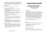
Figure1 Russound ceiling mount speakers may be used for rear surround sound channels by placing them (1) behind, (2) on each side of the viewing
position or (3) in the ceiling just behind the viewers. The available SP550.2 & SP650.1 speakers also make excellent, unobtrusive front channel home
theater speakers for 5 channel listening.
Figure 2
Dual Voice Coil
Speaker Placement

SPEAKER WIRE PATHS
In general, you should pay particular attention to the following areas:
• Avoid running speaker wires close to house electrical wiring for any
distance. If you have to run them parallel, make sure to space the
speaker wires at least two feet from the AC line. It is, however, okay
for speaker wires to cross paths with AC lines or go through the same
hole together with house wiring if they separate before and after.
• Make sure that the entire path between speakers and amplifier is
clear and not obstructed by a floor or ceiling joist or masonry wall
which you won’t be able to drill through.
• Remember that the other end of the wires has to come out some-
where to connect with the amplifier. Confirm ahead of time that
you can drill an outlet hole easily and in an un-obtrusive spot.
PAINTING THE SPEAKERS
If you like the designer white finish which has been applied to your
Russound Ceiling Speakers, skip to the section “cutting holes”. But if
you want your speakers to completely blend in with a colored wall or
accent the surface, now is the time to paint your Russound speakers’
outer frames and perforated grilles.
The speaker’s outer surfaces are primed to accept ordinary latex wall
paint or aerosol spray paint. Because the surface behind the perforated
grille should remain black, you will need to mask this area off before
you begin painting or use the included template cover.
1. Remove the speaker grilles. From the back of the speaker, push the
clamp (dog-ear) towards the grill to loosen it so you can pull it off.
2. Attach masking tape to the cardboard masking template which has
been included with your speakers.
3. Press the template onto each speaker’s surface to cover the woofer
and tweeter.
4. Paint the outer speaker frame and grille separately. A roller with a
short or medium nap will work much better than a brush. If you’re
using spray paint, make sure that you achieve the same coverage on
both grille and frame.
5. After the paint has thoroughly dried, remove the template and/or
masking tape.
There’s no need to replace the grill at this time since you will need
access to the inner speaker surface during installation.
CUTTING HOLES FOR THE SPEAKERS
Wallboard is an easy surface in which to make a relatively neat hole.
Make sure you don’t make it any bigger than the template. In the fol-
lowing steps, you’re going to locate a section of ceiling or wall between
two joists/studs, mark the outer boundaries of the hole, drill a small hole
in the center to confirm your location and then cut the main hole.
1. Determine the location of your joists/studs so that the speaker can be
approximately centered between them. There are several ways to go
about this:
- Tap on the wall and listen to the resulting “THUMP”. When it’s deep-
er, you’re between studs. When it’s sharper and more flat-sounding,
you’re close to a stud.
- Use a stud-finder, a simple little magnetic device which works by
locating the lines of nails hammered into the stud.
- Identify studs by the position of electrical outlets or switches. There
will be a stud either directly to the left or right of a an electrical fix-
ture. This gives you a point of measurement since studs are either 18
or 16 inches apart in newer houses, 12 inches apart on older homes.
2. When you’re reasonably sure of where the joists or 2x4 studs are (and
are TOTALLY sure that there isn’t an electrical cable, water pipe or
heating duct in that vicinity of wall), position one of the cardboard
mounting templates and draw an outline with a pencil. If you don’t
trust your eye, use a level to make sure the hole will be perfectly
round.
3. Drill a 1-inch hole in the center of the pencil outline which you have
just drawn.
4. Obtain a length of stiff wire such as an un-bent coat hanger. Bend it
so that the last 12 inches is at a right angle to the rest.
5. Insert the angled part into the 1-inch hole you just drilled and probe
to left and right to confirm that a joist or stud is not close on either
side.
- If there is a close joist/stud on one side, just re-position the card-
board template a few inches in the opposite direction and re-draw
your pencil outline, keeping the 1-inch hole within the pencil out-
line’s inner boundaries.
6. Score the outline of the template with a utility knife to prevent chip-
ping or wall paper from tearing. Then use a keyhole/dry-wall saw to
cut in the opening.
- If you’re dealing with lath and plaster or thick paneling, you need to
use a different technique. Drill 1-inch holes at the corners of the
pencil outline. Then use a fine-toothed key-hole saw or even a hack-
saw blade with VERY slow strokes to saw through and remove the
inner surface.
4

7. Temporarily place a Russound speaker into the cut-out to insure that
it fits properly. It’s okay if the hole is slightly off/larger by 1/8”, since
it will be covered by the speaker’s outside frame. Actual installation
will happen later, after you’ve routed the speaker wires.
8. Repeat steps 1 through 7 for the other speaker.
9. Now it’s time to drill the hole on the OTHER end -at the point where
the wires from the speakers will exit to the amplifier/receiver.
- Use the same 1-inch drill bit as before.
- If you want a custom look, install an outlet box against a stud and
cover it with a single outlet plate which has one hole in the middle
for the wires to exit from OR order from your Russound dealer a
Russound Stereo Pair Wall Plate Connector.
HOOKING UP YOUR SPEAKERS
IDENTIFYING “+” AND “-”
You need to be able to discriminate between the two conductors of the
speaker wire. If your wire has transparent insulation, this is easy: one
conductor will be copper-colored and the other silver-colored.
Generally, professionals denote the copper one as POSITIVE (+) and the
silver one as NEGATIVE (-).
If you’ve used wire which has an opaque insulation, there are still differ-
entiating markings. Examine the wire closely and look for
1. A series of ribs or grooves on one conductor
2. A painted stripe or dotted line
- Denote any of these as the POSITIVE (+) conductor for similar con-
nections on both ends.
NOTE: It is important that you label your wires left and right
when you run them to eliminate future confusion.
5
Figure 3
A. Trace template outline B. Drill 1-inch pilot hole
C. Probe with wire
for stud clearance
D. Cut speaker hole
along outline

AT THE SPEAKER END
1. Cut off excess wire, leaving about 2 feet extending through the
speaker cut-out hole.
2. Pull the conductors apart so they’re separated for the first two inches
from their ends.
3. Using a wire stripper, diagonal pliers or a knife, remove 1/2 inch of
insulation from each conductor.
4. Twist the tiny strands in each conductor into tight spirals, as shown
in Figure 4.
5. IMPORTANT: Route the speaker wire THROUGH the sheetrock as
shown in Figure 5.
6. Attach the speaker wires to the red
and black speaker terminals. Press down
on the protruding levers while inserting the
wire into the hole.
- Correct the POSITIVE (+) conductor to the RED
terminal and the NEGATIVE (-) conductor to the
BLACK speaker terminal.
- Make sure that no stray strands of wire have gotten detached and
are touching the other main wire.
7. Repeat Steps 1 through 6 for the other Russound Ceiling Speaker.
AT THE AMPLIFIER END
1. Cut off excess wire, leaving enough to comfortably reach from the
hole in the wall to your stereo system. If there’s a possibility that
you’re going to move the amplifier to another part of the room, con-
sider leaving some excess wire coiled up. If you’ve used sufficiently
thick wire, this extra length will not affect speaker performance and
could make re-routing easier if the room is rearranged later.
2. Pull the conductors on both speaker wires apart so they’re separated
for the last two inches.
3. Using wire strippers, diagonal pliers or a knife, remove 1/2 inch of
insulation from each conductor.
4. Twist the tiny strands in each conductor into tight spirals.
5. Attach the speaker wires to the red and black speaker terminals on
the amplifier or receiver.
* Connect the POSITIVE (+) conductor to the RED terminal and the
NEGATIVE (-) conductor to the BLACK speaker terminal of the receiv-
er/amplifier.
* Make sure that no stray strands of wire have gotten detached and
are touching the other main wire.
Repeat Steps 1 through 5 for the other speaker.
6
Figure 4
Figure 5
Figure 6

FINAL ASSEMBLY
1. If you haven’t done so already during painting, remove the perforat-
ed grilles from both Russound Speakers. Use the clamp (dog-ear) to
push the grille out from the back side.
2. Center the speaker in the cut-out hole and tighten the screws until
the clamps are drawn up snugly from behind, clamping the speaker
in place. Try to tighten each screw equally but do not over tighten.
3. For models SP503.1, SP522.1 and SP523.1, insert the Russound
speaker grille by gently pressing it into place. Now insert grill and
trim into the can by pushing the black trim ring with the grill in-first.
It will be a tight fit, so make sure it is going in straight.
In most installations, the grilles will fit tightly without causing vibration.
If any audible vibration does occur, or if your Russound speakers are
ceiling mounted, use the pre-cut lengths of special damping/adhesive
material. Remove the perforated grille, unwrap four of the damping
strips and affix them to the four outer corners of the inner speaker sur-
face. Then replace the grille.
A QUICK LISTENING TEST
It’s a good idea to test everything at this point.
1. Turn on your stereo system. Make sure that the VOLUME control is
turned down and that the BALANCE control is set to center.
2. Activate a musical source such as FM or CD player.
3. Gently turn up the volume. You should hear music coming out of
your new Russound In-Wall Speakers! (If you don’t, refer to the trou-
bleshooting guide below.)
4. Now rotate the stereo’s BALANCE control all the way to the LEFT.
Sound should only come out of your left in-wall speaker. If it comes
out of the RIGHT speaker, skip to Step 6.
5. Rotate the BALANCE control all the way to the RIGHT. Sound should
only come out of the right speaker.
6. If sound comes from the right speaker when the stereo’s balance
control is turned to the LEFT, you’ll need to change the connections
on the back of the amplifier/receiver.
* FIRST TURN OFF THE AMPLIFIER!
* Swap the wires attached to the left and right speaker terminals.
A QUICK TROUBLESHOOTING GUIDE
Before returning your Russound Speakers for service, it is a good idea to
check out these simple remedies first.
No sound from either speaker:
1. Incorrect source selected on receiver or preamplifier.
2. Mute button pressed on receiver.
3. Wrong speaker output selected; many receivers have an “A” and “B”
speaker switch. Make sure it’s in the right position.
4. In-Wall Volume control not turned up or wired incorrectly.
5. If using a “speaker selector”, room/station not turned on or improp-
erly connected.
No sound from one speaker:
1. Un-secure connection at either the speaker or amplifier-double-
check them.
2. Balance control turned all the way left or right-return it to center.
3. Bad connecting cable between sound source and amplifier - try a
new cable.
4. Defective speaker - contact your Russound dealer or call our cus-
tomer tech department at 603.659.5170.
• Any other problems not listed, discuss with your dealer or call
Russound.
7

TAKING CARE OF YOUR NEW CEILING SPEAKERS
RUSSOUND Ceiling Speakers are designed to last the life of your home if
you follow a few simple rules.
The main “killers” of any loudspeaker system are:
• too little power at high volumes
• too much power at high volumes
• transients (immediate loud passages, thumps, etc.)
Too little power:
It’s a surprising fact but far more speakers are damaged by too little
power than by too much! When an amplifier runs out of power while
trying to re-create musical peaks, it causes a form of high frequency dis-
tortion called clipping. Clipping simply makes the music sound distort-
ed. In greater quantities over a period of time, it can damage or destroy
the tweeters (high frequency speakers) in any speaker system. If you like
your music LOUD, consider getting an amplifier with at least 50 watts
per channel.
Too much power:
There’s nothing wrong with driving your Russound speakers with as
much as 80 watts per channel—the extra power helps them achieve
quick musical transients found in digital recordings. However, you must
remember to restrain yourself and not get too heavy-handed with the
volume control (or remote buttons). If the music begins to sound dis-
torted or you hear a “clacking” sound during bass notes, back off! The
clacking is caused by the woofer’s voice coil trying to come out of its
socket.
Transients:
Loud, deep THUMPS, caused when your system is turned on/off, or when
the tonearm is dropped too hard on a record (if you still use those great
classics), can seriously damage any loudspeaker including your Russound
Ceiling models. Also remember to turn your system off before discon-
necting any hook-up cables. When they’re pulled out, a huge burst of
low frequency hum often occurs if the system is still on.
MORE ON SPEAKER WIRES AND AMPLIFIER IMPEDANCE
Not all amplifiers or receivers can safely operate two sets of speakers at
once. If you intend to use your Russound Ceiling Speakers at the same
time as your main speakers or if you intend to hook up two pairs of
speakers and use both at the same time, it’s important to consider both
the impedance of the speakers and the capabilities of the amplifier
you’re using. Russound makes a complete line of products from
Impedance-Matching Volume Controls to Impedance-Matching Speaker
Selectors. Ask you Russound dealer for details or simply write your
request for a line catalog to Russound or FAX us at 603.659.5388
First, consult the owner’s manual that came with the amp or receiver. It
should tell you the minimum speaker impedance during simultaneous
operation. On some models the manual will recommend that only two
pairs of 8-ohm speakers be used at the same time. Others might allow
one set of 8-ohm speakers and one set of 4-ohm impedance speakers.
A few extremely powerful receivers and power amplifiers may even
allow two sets of 4-ohm speakers.
If you can’t readily determine this information, consult the dealer where
you purchased the amplifier, or call the manufacturer of the product in
question. Next, determine the impedance of your other speakers. It’s
often printed on the back of the enclosure near the connection termi-
nals, or you can consult the speaker’s owners manual.
If your other speakers are rated at 4-ohms, some amplifiers may experi-
ence difficulty driving both 4-ohm sets at once and shut off intermit-
tently when the volume control is turned up. In this case, you should
operate only one set of speakers at a time or keep the volume extremely
low.
Another option is to purchase a speaker selector such as the Russound
SS4 & SS6 series or a PRO series speaker selector. These are designed to
maintain impedance control allowing your amplifier to work efficiently.
8

INSTALLING DURING NEW CONSTRUCTION
Needless to say, installing In-Wall speakers when a house is being built is
far easier than doing it later. Russound offers a Speaker Rough-In
Brackets for round speakers (Model SB-1.5). The bracket is designed to
provide the drywall installers the cut-out for the In-Walls. Each kit
comes with two brackets, (one is required per speaker). The brackets are
nailed/screwed onto the wall studs. Once the house/room is completed,
you can install the speaker (more on this below).
During new installation, keep the following tips in mind:
• Use a small level to verify that the mounting frame is straight.
• The flat brackets and nails which attach the speakers are thin enough
that they won’t interfere with wallboard added later.
• If possible, run speaker wires after AC wiring is in place to avoid
induced hum caused by close parallel proximity.
• Secure speaker wires in place along the run with insulated staples
only and be careful not to pierce the insulation. Allow a bit of slack
for expansion of building materials.
• The actual speakers should not be installed until the wall board is in
place. In the meantime, leave several feet of wire coiled up and
secured to the back side of the mounting frame.
• When it comes time to put up the dry wall, make sure the speaker
cut-out hole doesn’t extend farther than 1/4” from the sides of the
mounting frame.
• After the wallboard is put up, install the speakers as detailed on page
9 of this manual.
Due to our continual efforts to improve product quality as new technol-
ogy and techniques become available, Russound/FMP, Inc. reserves the
right to revise speaker systems specifications without notice.
WARRANTY
All Russound Speaker products are fully guaranteed against all defects in
materials and workmanship for five years from date of purchase. Proof
of Receipt must accompany all claims. During the warranty period
Russound will replace any defective part and correct any defect in work-
manship without charge for either parts or labor. For this warranty to
apply, the unit must be installed and used according to its written
instructions. If necessary, repairs must be performed by Russound. The
unit must be returned to Russound at the owner’s expense and with
prior written permission. Accidental damage and shipping damage are
not considered defects, nor is damage resulting from abuse or from ser-
vicing performed by an agency or person not specifically authorized in
writing by Russound. Damage to or destruction of components due to
application of excessive power voids the warranty on those parts. In
these cases repairs will be made on the basis of the retail value of the
parts and labor. To return for repairs, the unit must be shipped to
Russound at the owner’s expense, along with a note explaining the
nature of service required. Be sure to pack in a corrugated container
with at least 3 inches of resilient material to protect the unit from dam-
age in transit.
This Warranty Does Not Cover:
• Damage caused by abuse, accident, misuse, negligence, or improper
operation (installation).
• Products that have been altered or modified.
• Any product whose identifying number or decal, serial #, etc. has
been altered, defaced or removed.
• Normal wear and maintenance.
9
Figure 7

TECHNICAL SPECIFICATIONS
SP503.1
Frequency Response: 68Hz - 18kHz
Construction: Dual Voice Coil, Dual Drive 5.25" Polymica cone with coni-
cal high frequency driver. Moisture resistant
Sensitivity: 88dB
Min / Max Power: 10 to 60 W/Channel
Impedance: 4 Ohm, 8 Ohm, 16 Ohm (depending on wiring)
Frame: ABS plastic, paintable
Grille: Fine mesh grille, paintable (steel),
Mounting: 4 self-mounting, self-contained clamps
Dimensions: 6.5"OD x 5.25"ID x 3"D
SP522.1
Frequency Response: 65-21,000Hz
Construction: 5.25" Poly cone, Dual voice coil woofer with Butyl rubber
surround. Two 13mm Mylar dome tweeters. Moisture resistant
Sensitivity: 89 dB
Min/Max Power: 10 to 60 W/Channel
Impedance: 8 Ohm
Frame: ABS plastic, paintable
Grille: Fine mesh grille, paintable (steel),
Mounting: 4 self-mounting, self-contained clamps
Dimensions: 6.5"OD x 5.25"ID x 3"D
SP523.1
Frequency Response: 65Hz - 20kHz
Construction: 5.25" Polymica woofer, .5" Neodymium mylar dome swivel
tweeter. Moisture resistant
Sensitivity: 90dB
Min / Max Power: 10 to 60 W/Channel
Impedance: 8 Ohm
Frame: ABS plastic, paintable
Grille: Fine mesh grille, paintable (steel)
Mounting: 4 self-mounting, self-contained clamps
Dimensions: 6.5"OD x 5.25"ID x 3"D
10

NOTES
11

A/V DISTRIBUTION & CONTROL SYSTEMS
5 Forbes Rd. Newmarket, NH 03857, USA
☎ 603.659.5170 • Fax 603.659.5388
e-mail: [email protected]
Fax-On-Demand: 603.659.5590
Come visit us at:
/