8
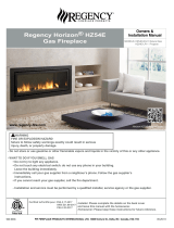
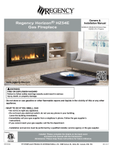
Regency Horizon HZ54E Gas Fireplace
INSTALLATION
10) Be aware of electrical wiring locations in walls
and ceilings when cutting holes for termination.
11) Under no circumstances should this appliance
be modifi ed. Parts that have to be removed for
servicing should be replaced prior to operating
this appliance.
12) Installation and any repairs to this appliance
should be done by an authorized service per-
son. A professional service person should be
called to inspect this appliance annually. Make
it a practice to have all of your gas appliances
checked annually.
13) Do not slam shut or strike the glass door.
14) Under no circumstances should any solid fuels
(wood, paper, cardboard, coal, etc.) be used in
this appliance.
15) The appliance area must be kept clear and
free of combustible materials, (gases and other
fl ammable vapours and liquids).
Emissions from burning wood or gas could
contain chemicals known to the State of
California to cause cancer, birth defects or
other reproductive harm.
IMPORTANT MESSAGE
SAVE THESE
INSTRUCTIONS
The HZ54E Direct Vent Fireplace must be installed
in accordance with these instructions. Carefully
read all the instructions in this manual fi rst. Consult
the "authority having jurisdiction" to determine the
need for a permit prior to starting the installation.
It is the responsibility of the installer to ensure
this fi replace is installed in compliance with
manufacturers instructions and all applicable codes.
BEFORE YOU START
Safe installation and operation of this appliance
requires common sense, however, we are required
by the Canadian Safety Standards and ANSI
Standards to make you aware of the following:
GENERAL SAFETY
INFORMATION
1) The appliance installation must conform with lo-
cal codes or, in the absence of local codes, with
the current Canadian or National Gas Codes,
CAN1-B149 or ANSI Z223.1 Installation Codes.
2) The appliance when installed, must be electri-
cally grounded in accordance with local codes,
or in the absence of local codes with the current
National Electrical Code, ANSI/NFPA 70 or CSA
C22.1 Canadian Electrical Code.
3) See general construction and assembly in-
structions. The appliance and vent should be
enclosed.
4) This appliance must be connected to the speci-
fi ed vent and termination cap to the outside of
the building envelope. Never vent to another
room or inside a building. Make sure that the
vent is fi tted as per Venting instructions.
5) Inspect the venting system annually for blockage
and any signs of deterioration.
6) Venting terminals shall not be recessed into a
wall or siding.
7) Any safety glass removed for servicing must
be replaced prior to operating the appliance.
8) To prevent injury, do not allow anyone who is
unfamiliar with the operation to use the fi replace.
9) Wear gloves and safety glasses for protection
while doing required maintenance.
CHILDREN AND ADULTS SHOULD BE
ALERTED TO THE HAZARDS OF HIGH
SURFACE TEMPERATURES, ESPE-
CIALLY THE FIREPLACE GLASS, AND
SHOULD STAY AWAY TO AVOID BURNS
OR CLOTHING IGNITION.
INSTALLATION AND REPAIR SHOULD
BE DONE BY AN AUTHORIZED
SERVICE PERSON. THE APPLIANCE
SHOULD BE INSPECTED BEFORE
USE AND AT LEAST ANNUALLY BY A
PROFESSIONAL SERVICE PERSON.
MORE FREQUENT CLEANING MAY
BE REQUIRED DUE TO EXCESSIVE
LINT FROM CARPETING, BEDDING
MATERIAL, ETC. IT IS IMPERATIVE THAT
CONTROL COMPARTMENTS, BURNERS
AND CIRCULATING AIR PASSAGEWAYS
OF THE APPLIANCE BE KEPT CLEAN.
DUE TO HIGH TEMPERATURES, THE
APPLIANCE SHOULD BE LOCATED
OUT OF TRAFFIC AND AWAY FROM
FURNITURE AND DRAPERIES.
WARNING: FAILURE TO INSTALL THIS
APPLIANCE CORRECTLY WILL VOID
YOUR WARRANTY AND MAY CAUSE A
SERIOUS HOUSE FIRE.
CLOTHING OR OTHER FLAMMABLE
MATERIAL SHOULD NOT BE PLACED
ON OR NEAR THE APPLIANCE.
YOUNG CHILDREN SHOULD BE CARE-
FULLY SUPERVISED WHEN THEY ARE
IN THE SAME AREA AS THE APPLI-
ANCE. TODDLERS, YOUNG CHILDREN
AND OTHERS MAY BE SUSCEPTIBLE
TO ACCIDENTAL CONTACT BURNS. A
PHYSICAL BARRIERS IS RECOMMEND-
ED IF THERE ARE AT RISK INDIVIDUAL
IN THE HOUSE. TO RESTRICT ACCESS
TO A FIREPLACE OR STOVE, INSTALL
AN ADJUSTABLE SAFETY GATE TO
KEEP TODDLERS, YOUNG CHILDREN
AND OTHER AT RISK INDIVIDUALS OUT
OF THE ROOM AND AWAY FROM HOT
SURFACES.