Excalibur electronic PR10 User manual
- Category
- Toy vehicles
- Type
- User manual
This manual is also suitable for

Model No. PR10
User’s Guide for
Motorized Pool Lounger
www.ExcaliburElectronics.com

C
ongratulations on your purchase of the Motorized
Pool Lounger from Excalibur Electronics, Inc. You
and your friends will enjoy hours of outdoor fun
with this innovative product. Your Motorized Pool Lounger
contains two propellers which enable you to turn in all
directions.
Your Motorized Pool Lounger is easy to use, but be sure
to use it safely. Before starting, please read this manual thor-
oughly, especially noting the safety and care. Keep this
manual for reference.
Your Motorized Pool Lounger requires some assem-
bly. This package includes one pool lounger. For each side
of the pool lounger, it includes a battery compartment, a
battery cover and handle, a control arm, a control arm sleeve,
an electrical connection shaft, a lug nut, a motor assembly
that encloses the propeller. Additionally, a bag of bolts, o-
rings, metal washers, rubber washers and a lug nut wrench,
a restoration kit, an instructional DVD and its user's guide
are included to facilitate assembly. These are illustrated in
Figures one through ten on pages four and five.
The legendary King Arthur brandished a
magic sword, Excalibur
, from which we take
our company name. With this unique weapon
in his hands, he could not be vanquished.
Although Excalibur Electronics can’t claim
the magical secrets of Merlin, King Arthur’s
court wizard, sometimes our patented
technology may make it seem as if we could.
We make you think.
Table of Contents
What’s Included. . . . . . . . . . . . . . . . . . . . . .page 4
How to Use.
. . . . . . . . . . . . . . . . . . . . . . . . page 6
Setting Up the Motorized Pool Lounger
. . .page 6
Inflation
. . . . . . . . . . . . . . . . . . . . . . . . page 6
Assembly
. . . . . . . . . . . . . . . . . . . . . . . page 8
Testing the Motorized Pool Lounger
. . . . . page 12
Using the Motorized Pool Lounger
. . . . . page 12
Disassembly
. . . . . . . . . . . . . . . . . . . . . page 13
Repairing the Motorized Pool Lounger
. . . page15
Warning . . . . . . . . . . . . . . . . . . . . . . . . . . . page 17
Special Care & Handling . . . . . . . . . . . . . . . page 18
Battery Information.
. . . . . . . . . . . . . . . . . . .page 19
How Use the Electric Air Pump
. . . . . . . . . . .page 20
Limited 90-Day Warranty
. . . . . . . . . . . . . . . page 23
3
2

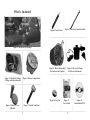
What’s Included
Figure 1: Motorized Pool Lounger
Figure 2: Nuts, Bolts, Washers
O-Rings and Restoration Kit
Figure 3: Battery Compartment
Figure 4: Battery Cover
& Handle
Figure 5: Control Arm Sleeve
Figure 6 Control Arm
Figure 7: Electrical Connection Shaft
Figure 10: Lug Nut
Figure 8: Motor Subassembly
that Encloses the Propeller
4
5
Figure 11:
User’s Guide
Figure 12:
Instructional DVD
Figure 9: Electric Air Pump
with Nozzle Attachments

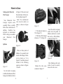
How to Use
Setting up the Motorized
Pool Lounger
Your Motorized Pool
Lounger requires some
assembly. Please carefully
follow these instructions. In
addition, Excalibur has
included an instructional
DVD to help you assemble
your Motorized Pool
Lounger.
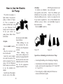
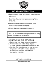
Inflation
Figure 13
Use the electric air pump
to inflate the Motorized Pool
Lounger (included) as shown
in Figure 13. Be sure to read
the instructions for the elec-
tric air pump on page 20.
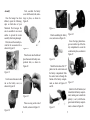
Insert the medium-size
valve into the electric air
pump, as shown in Figure
14.
Figure 14
There are three points of
inflation. It is generally best
to start at the lounger’s back-
rest (as shown as ‘A’ in
Figure 15) and then proceed
forward in the following
sequence, shown in Figures
15 and 16.
Figure 15
1. The armrests (shown as
‘B’ in Figure 15).
2. The body of the lounger
(shown as ‘C’ in Figure 16).
Figure 16
Remove the valve cover,
as shown in Figure 17.
Figure 17
Insert the electric air pump
nozzle into the points of
inflation and turn it on until
that cavity is fully inflated,
as shown in Figure 18.
Figure 18
After finishing with each
section, be sure to securely
close each valve cover.
67

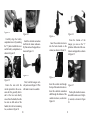
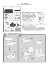
Assembly
Once the lounger has been
inflated, repeat the following
steps on both sides of your
Motorized Pool Lounger. Be
sure to assemble it on a raised
surface to prevent the motor
assembly from being damaged.
First, take out the wrench pro-
vided in the accessories kit as
shown in Figure 19.
Figure 19
Use the wrench to unscrew the
nut on the battery cover, as
shown in Figure 20.
Figure 20
Next, assemble the battery
cover with the nuts, bolts, and o-
rings in place, as shown in
Figure 21.
Figure 21
Place the nut onto the bolt and
place them onto the battery com-
partment hole, as shown in
Figure 22.
Figure 22
Place an o-ring on the end of
the bolt, as shown in Figure 23.
Figure 23
Finish assembling the battery
cover, as shown on Figure 24.
Figure 24
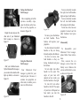
Match the direction of the “2”
printed on the control arm and
the battery compartment. Slide
the control arm in through the
bottom of the battery compart-
ment, as shown in Figures 25
and 26.
Figure 25
Figure 26
Screw the large plastic hexa-
gon nut onto the top of the bat-
tery compartment to secure the
control arm in place, as shown in
Figure 27.
Figure 27
Install six D-cell batteries (not
included) in the battery compart-
ment, making sure to match the
polarity (+ and -) with the dia-
gram inside the battery compart-
ment, as shown in Figure 28.
89

Figure 28
Carefully align the battery
compartment cover by matching
the “3” printed on both the cover
and the battery compartment, as
shown in Figure 29.
Figure 29
Fasten the nuts with the
wrench provided in the acces-
sories kit. It is generally best to
start at the two nuts directly
across from the handle, then the
two nuts on both sides of the
handle, then the last remaining
two, as shown in Figure 30.
Figure 30
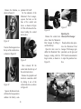
Insert the electrical connection
shaft into the motor subassem-
bly that encloses the propeller, as
shown in Figure 31.
Figure 31
Next, hold the lounger verti-
cally as shown in Figure 32. This
will make it easier to assemble.
Figure 32
Insert the control arm sleeve
into the holes located on the
armrest, as shown in Figure 33.
Figure 33
Insert the control arm through
the top of the control arm sleeve.
Insert the electrical connection
shaft through the bottom of the
control arm sleeve, as shown in
Figure 34.
Figure 34
From the bottom of the
lounger, you can see the “1”
printed on both sides of the con-
trol arm and propeller, as shown
in Figure 35.
Figure 35
Push up the electrical connec-
tion shaft to make sure it’s tight-
ly secured, as shown in Figure
36.
10 11

12 13
Figure 36
Repeat the same steps on the
other side of your Motorized
Pool Lounger, as shown in
Figure 37.
Figure 37
After you’ve finished assem-
bly the Motorized Pool Lounger,
you can store the wrench on the
right cup holder, as shown in
Figure 38.
Figure 38
Testing the Motorized
Pool Lounger
After completing all of the
previous assembly steps,
press the button on the han-
dle to test the propeller, as
shown in Figure 38.
Figure 38
Using the Motorized
Pool Lounger
Your Motorized Pool
Lounger is perfect for your
backyard pool. Because it
contains two propellers on
either side, it enables you to
move in all directions.
Figure 39
To move, press the buttons
on both handles. These
buttons will operate your
propellers.
To drive forward, turn both
handles so they are facing
forward and press the buttons.
To drive in reverse, turn
both handles so they are
facing backward and press
the buttons.
To turn right, turn either
handle to the right. The
angle of your turn will
depend on how much you
turn the handles to the right.
To turn left, turn either
handle to the left. The angle
of your turn will depend on
how much you turn the
handles to the left.
To move laterally towards
the right, turn both handles
right and press both buttons.
To move laterally towards
the left, turn both handles
left and press both buttons.
To turn in a circle, face one
propeller forward and the
other backward and press
the buttons.
Disassembly
To disassemble your
Motorized Pool Lounger,
please follow these instruc-
tions.
First, unscrew the six
hexagon screws from the
battery cover. Remove the
screws and the battery cover,
as shown in Figure 40.
Figure 40

14
Remove the batteries, as
shown in Figure 41.
Figure 41
Unscrew the hexagon nut on
the top of the control sleeve,
as shown in Figure 42.
Figure 42
Squeeze the fastener locat-
ed below the hexagon nut to
unfasten the battery com-
partment. Lift it off.
On the underside of the
Motorized Pool Lounger,
squeeze the holes on the
base of the control arm
sleeve, as shown in Figure
43. This will release the fas-
teners holding the control
arm in place.
Figure 43
Once released, lift the
control arm from the top of
the control arm sleeve.
Remove the propeller and
electrical connection shaft
by sliding it out of the
control arm sleeve, as shown
in Figure 44.
Figure 44
Remove the control arm
sleeve from the Motorized
Pool Lounger by lifting it
out from the top.
Open the valve cover to
deflate the Motorized Pool
Lounger, starting with the
larger cavities, as shown in
Figure 45.
Figure 45
Repairing the
Motorized Pool Lounger
Rough surfaces may punc-
ture the Motorized Pool
Lounger. If the lounger gets
punctured, use the glue and
PVC from the restoration kit
to repair the punctured sur-
face.
15

Warning
• Please read the User's Guide carefully before operating the
product.
• Children under 14 years of age should not operate this
product without parental supervision.
• This product is designed for pool use only. It may be used in
ponds or small lakes only within the range of the user’s com
fortable ability to swim to shore provided that there are no
strong currents, waves, or water crafts present which could
create wakes. Do not use in any other body of water or salt
water.
• This product is designed to hold one person not exceeding
250lbs/115kg.
• Keep hands, hair, and loose objects such as clothing away from
the propeller.
• If an object becomes lodged in the propeller, make sure that
this product is turned off before attempting to dislodge.
• Always inspect the pool area before use to ensure it is free of
hazards and/or obstacles, such as pool toys and swimmers.
• Never ride into or over swimmers.
• Keep this product away from hot or sharp objects.
• Always use caution and common sense.
• Never jump or dive off this product.
Apply the glue on the
damaged area and apply the
supplementary PVC sheet.
Wait approximately one
minute for the glue to dry
after applying the PVC sheet
before handling your
Motorized Pool Lounger.
You should wait approxi-
mately 24 hours before
using the Motorized Pool
Lounger in your pool again.
Figure 46
16 17

19
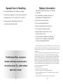
Battery Information
• Your Motorized Pool Lounger uses six D batteries,
not included.
• Do not mix alkaline, standard (carbon-zinc) or
rechargeable nickel-cadmium) batteries.
• Do not mix old and new batteries.
• Do not use rechargeable batteries.
• Remove exhausted batteries from the unit.
• Do not short circuit battery terminals.
• Remove batteries and store them in a cool,
dry place when not in use.
• To avoid explosion or leakage, do not dispose of
batteries in a fire or attempt to recharge alkaline
or other non-rechargeable batteries.
Special Care & Handling
• Avoid rough handling such as bumping or dropping.
• Avoid extreme temperatures. For best results use between
the temperatures of 39° F and 120° F (4° C and 38° C).
• Clean using only a slightly damp cloth. Do not
use cleaners with chemical agents.
THE MOTORIZED POOL LOUNGER IS
NEITHER A PERSONAL
-FLOTATION NOR A
LIFE
-SAVING DEVICE. ALL USERS SHOULD
KNOW HOW TO SWIM
.
18
This device complies with Part 15 of the FCC Rules. Operation is subject to the fol-
lowing two conditions: (1) this device may not cause harmful interference, and (2) this
device must accept any interference received, including interference that may cause unde-
sired operation.
NOTE: This equipment has been tested and found to comply with the limits for a Class
B digital device, pursuant to Part 15 of the FCC Rules. These limits are designed to
provide reasonable l interference in a residential installation. This equipment generates,
uses and can radiate radio frequency energy and, if not installed and used in accor-
dance with the instructions, may cause harmful interference to radio communications.
However, there is no guarantee that interference will not occur in a particular installa-
tion. If this equipment does cause harmful interference to radio or television reception,
which can be determined by turning the equipment off and on, the user is encouraged
to try to correct the interference by one or more
of the following measures:
• Reorient or relocate the receiving antenna.
• Increase the separation between the equipment and receiver.
• Connect the equipment into an outlet on a circuit different from that to which the
receiver is connected.
• Consult the dealer or an experienced radio/TV technician for help.

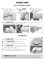
The electric air pump is a
high-volume, low-pressure
pump, as shown in Figure
47. This is intended to
inflate or deflate items, such
as your Motorized Pool
Lounger and air mattresses.
To use your electric air
pump, please follow these
instructions.
To Inflate
Turn the ON/OFF switch to
OFF.
Plug the electrical cord
into a wall socket.
Insert the correct adapter
size onto the nozzle of the
electric air pump. If you are
using it for the Motorized
Pool Lounger, you will need
to use the medium size
adapter.
Insert the tip of the adapter
into the valve of the inflat-
Figure 47
able item and switch ON to
begin inflation.
While inflating, be sure
not to obstruct the valve.
This may cause the pump to
overheat.
When inflating large
items, such as a king-size air
mattress, the pump should fit
directly into the valve of the
inflatable item for fast infla-
tion. Use the appropriate
adapter for smaller valves.
How to Use the Electric
Air Pump
To Deflate
To deflate an inflatable
item, open the valves of the
inflated item. You can either
allow it to deflate on its own.
If you want to expedite the
deflation process, follow
these instructions.
Turn the
ON/OFF switch to
OFF. Plug the electrical cord
into a wall socket.
Insert the deflation port
(located on the top of the
electric air pump) into the
valve of the inflatable item
and switch
ON to begin de-
flation.
20 21
Special Care & Handling for the Electric Air Pump
• Avoid rough handling, such as bumping or dropping.
• Avoid moisture and extreme temperatures. For best
results, use between the temperatures of 39˚ F and 100˚ F
(4˚ C and 38˚ C).
• Clean using only a slightly damp cloth. Do not use
cleaners with chemical agents.
Figure 48 Figure 49

EXCALIBUR ELECTRONICS,
INC., warrants to the original con-
sumer that its products are free from
any electrical or mechanical defects
for a period of 90 DAYS from the
date of purchase. If any such defect
is discovered within the warranty
period, EXCALIBUR ELECTRON-
ICS, INC., will repair or replace the
unit free of charge upon receipt of
the unit, shipped postage prepaid
and insured to the factory address
shown at right.
The warranty covers normal con-
sumer use and does not cover dam-
age that occurs in shipment or failure
that results from alterations, acci-
dent, misuse, abuse, neglect, wear
and tear, inadequate maintenance,
commercial use, or unreasonable use
of the unit. Removal of the top panel
voids all warranties. This warranty
does not cover cost of repairs made
or attempted outside of the factory.
Any applicable implied warranties,
including warranties of mer-
chantability and fitness, are hereby
limited to 90 DAYS from the date of
purchase. Consequential or inciden-
tal damages resulting from a breach
of any applicable express or implied
warranties are hereby excluded.
Some states do not allow limitations
on the duration of implied warranties
and do not allow exclusion of inci-
dental or consequential damages, so
the above limitations and exclusions
in these instances may not apply.
The only authorized service center
in the United States is:
Excalibur Electronics, Inc.
13755 SW 119th Ave
Miami, Florida 33186 U.S.A.
Phone: 305.477.8080
Fax: 305.477.9516
www.ExcaliburElectronics.com
Ship the unit carefully packed,
preferably in the original carton, and
send it prepaid, and adequately
insured. Include a letter, detailing the
complaint and including your day-
time telephone number, inside the
shipping carton.
If your warranty has expired and you
want an estimated fee for service,
write to the above address, specify-
ing the model and the problem.
PLEASE DO NOT SEND
YOUR UNIT WITHOUT
RECEIVING AN ESTIMATE FOR
SERVICING. WE CANNOT
STORE YOUR UNIT!
Play games live at: www.ExcaliburElectronics.com
Limited 90-Day Warranty
22 23
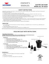
Warning for Electric Air Pump
• This appliance has a polarized plug (one blade is wider than the
other). To reduce the risk of electric shock, this plug is
intended to fit into a polarized outlet only one way. If the plug
does not fit fully into the outlet, reverse the plug. If it still does
not fit, consult an appliance repair-person. Do not attempt to
force the plug into the wall outlet.
•
To reduce the risk of electric shock, do not use if the
power cord appears damaged.
• Never over-inflate an item. The pressure may cause the
item to burst.
• Do not leave the pump unintended while it's turned on.
• Do not use the pump in wet conditions.
• Do not face the ports of the pump towards your face,
especially your eyes.
• Do not insert fingers or other objects into the ports of the
pump at any time.
• Do not place the pump on the ground when turned it. It
could suck in rocks and other small objects. This will
break the pump.
• Do not use this fan with any solid-state speed control
device.
• Do not leave the pump on for an extended period of time.
This may burn out the motor.
• Keep out of reach of children.

E
XCALIBUR
E
LECTRONICS
, I
NC
.
13755 SW 119
TH
A
VENUE
,
M
IAMI
, F
LORIDA
33186 U.S.A.
Phone: 305.477.8080
Fax: 305.477.9616
Play games live at:
www.ExcaliburElectronics.com
PR10 (MA) Motorized Pool Lounger 020306-V5
-
 1
1
-
 2
2
-
 3
3
-
 4
4
-
 5
5
-
 6
6
-
 7
7
-
 8
8
-
 9
9
-
 10
10
-
 11
11
-
 12
12
-
 13
13


Excalibur electronic PR10 User manual
- Category
- Toy vehicles
- Type
- User manual
- This manual is also suitable for
Ask a question and I''ll find the answer in the document
Finding information in a document is now easier with AI
Related papers
-
 Excalibur electronic 9366 User manual
-
 Excalibur electronic 9345 User manual
-
 Excalibur electronic Games EI-PT1001 User manual
-
 Excalibur electronic PR40S-1 User manual
-
 Excalibur electronic H639S-WC User manual
-
 Excalibur electronic EI-PT1013 User manual
-
 Excalibur electronic 904 User manual
-
 Excalibur electronic SMART CITY COUPE 9390 User manual
-
 Excalibur electronic 344 User manual
-
 Excalibur electronic SF20-2 User manual


Other documents
-
 BigMouth BMST-0031 Operating instructions
-
Hathaway BG50344 User manual
-
Protocol 4382-2AA Porta Lounger User manual
-
 S R Smith DS-1-61-2PK User manual
-
 S R Smith D898.391 User manual
-
 S.R.Smith R-Series™ Rotomolded Lounger In Pool-Chair Owner's manual
-
Excalibur Water Fusion Car EI-PT1010 User manual
-
 Beautyrest HDDOD7112DB Operating instructions
-
 XPOWER AP-1031A Owner's manual
-
XPOWER AP-1131 Owner's manual


