Milan Technology ShAir AccessG Pro MIL-W2332G User manual
- Category
- WLAN access points
- Type
- User manual
This manual is also suitable for

MIL-W2332G
ShAir™ AccessG Pro Wireless
Access Point/Bridge with PoE
USER GUIDE

ii

i
Regulatory Approval
- FCC Class A
- UL 1950
- CSA C22.2 No. 950
- EN60950
- CE
- EN55022 Class A
- EN55024
Canadian EMI Notice
This Class A digital apparatus meets all the requirements of the Canadian Interference-Causing Equipment Regulations.
Cet appareil numerique de la classe A respecte toutes les exigences du Reglement sur le materiel brouilleur du Canada.
European Notice
Products with the CE Marking comply with both the EMC Directive (89/336/EEC) and the Low Voltage Directive (73/23/EEC)
issued by the Commission of the European Community Compliance with these directives imply conformity to the following
European Norms:
EN55022 (CISPR 22) - Radio Frequency Interference
EN61000-X - Electromagnetic Immunity
EN60950 (IEC950) - Product Safety
Three-Year Limited Warranty
MiLAN Technology warrants to the original consumer or purchaser that each of it's products, and all components
thereof, will be free from defects in material and/or workmanship for a period of three years from the original factory
shipment date. Any warranty hereunder is extended to the original consumer or purchaser and is not assignable.
MiLAN Technology makes no express or implied warranties including, but not limited to, any implied warranty of mer-
chantability or fitness for a particular purpose, except as expressly set forth in this warranty. In no event shall MiLAN
Technology be liable for incidental or consequential damages, costs, or expenses arising out of or in connection with
the performance of the product delivered hereunder. MiLAN Technology will in no case cover damages arising out of
the product being used in a negligent fashion or manner.
Trademarks
The MiLAN logo and MiLAN Technology trademarks are registered trademarks of MiLAN Technology in the
United States and/or other countries.
To Contact MiLAN Technology
For prompt response when calling for service information, have the following information ready:
- Product serial number and revision
- Date of purchase
- Vendor or place of purchase
You can reach MiLAN Technology technical support at:
E-mail: [email protected]
Telephone: +1.408.744.2751
Fax: +1.408.744.2771
MiLAN Technology
1329 Moffett Park Drive
Sunnyvale, CA 94089
United States of America
Telephone: +1.408.744.2775
Fax: +1.408.744.2793
http://www.milan.com
© Copyright 2005 MiLAN Technology P/N: 90000
435 Rev.A

ii
Federal Communication Commission Interference Statement
This equipment has been tested and found to comply with the limits for a Class B digital device,
pursuant to Part 15 of the FCC Rules. These limits are designed to provide reasonable protec-
tion against harmful interference in a residential installation. This equipment generates, uses
and can radiated radio frequency energy and, if not installed and used in accordance with the
instructions, may cause harmful interference to radio communications. However, there is no
guarantee that interference will not occur in a particular installation. If this equipment does
cause harmful interference to radio or television reception, which can be determined by turning
the equipment off and on, the user is encouraged to try to correct the interference by one of the
following measures:
Reorient or relocate the receiving antenna.
Increase the separation between the equipment and receiver.
Connect the equipment into an outlet on a circuit different from that to which the receiver is
connected.
Consult the dealer or an experienced radio/TV technician for help.
FCC Caution: To assure continued compliance, (example – use only shielded interface cables
when connecting to computer or peripheral devices). Any changes or modifications not ex-
pressly approved by the party responsible for compliance could void the user’s authority to op-
erate this equipment.
This transmitter must not be co-located or operating in conjunction with any other antenna or
transmitter.
FCC Radiation Exposure Statement
This equipment complies with FCC radiation exposure limits set forth for an uncontrolled envi-
ronment. This equipment should be installed and operated with minimum distance 20 cm be-
tween the radiator & your body.
This device complies with Part 15 of the FCC Rules. Operation is subject to the following two
conditions: (1) This device may not cause harmful interference, and (2) this device must accept
any interference received, including interference that may cause undesired operation.

iii
R&TTE Compliance Statement
This equipment complies with all the requirements of DIRECTIVE 1999/5/CE OF THE EURO-
PEAN PARLIAMENT AND THE COUNCIL OF 9 March 1999 on radio equipment and telecom-
munication terminal equipment and the mutual recognition of their conformity (R&TTE).
The R&TTE Directive repeals and replaces in the directive 98/13/EEC (Telecommunications
Terminal Equipment and Satellite Earth Station Equipment) as of April 8,2000.
Safety
This equipment is designed with the utmost care for the safety of those who install and use it.
However, special attention must be paid to the dangers of electric shock and static electricity
when working with electrical equipment. All guidelines of this and of the computer manufacture
must therefore be allowed at all times to ensure the safe use of the equipment.
EU Countries Intended for Use
The ETSI version of this device is intended for home and office use in Austria, Belgium, Den-
mark, Finland, France (with Frequency channel restrictions), Germany, Greece, Ireland, Italy,
Luxembourg, Portugal, Spain, Sweden, The Netherlands, and United Kingdom.
The ETSI version of this device is also authorized for use in EFTA member states Norway and
Switzerland.
EU Countries Not Intended for Use
None.
Potential Restrictive Use
France: only channels 10, 11, 12, and 13.

iv
Table of Contents
1. Introduction
1.1. Overview
1.2. Features
1.3. LED Definitions
2. First-Time Installation and Configuration
2.1. Selecting a Power Supply Method
2.2. Mounting the AP on a Wall
2.3. Preparing for Configuration
2.3.1. Connecting the Managing Computer and the AP
2.3.2. Changing the TCP/IP Settings of the Managing Computer
2.4. Configuring the AP
2.4.1. Entering the User Name and Password
2.4.2. Step 1: Selecting an Operational Mode
2.4.3. Step 2: Configuring TCP/IP Settings
2.4.4. Step 3: Configuring IEEE 802.11 Settings
2.4.5. Step 4: Reviewing and Applying Settings
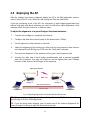
2.5. Deploying the AP
2.6. Setting up Client Computers
2.6.1. Configuring IEEE 802.11g-Related Settings
2.6.2. Configuring TCP/IP-Related Settings
2.7. Confirming the Settings of the AP and Client Computers
2.7.1. Checking if the IEEE 802.11g-Related Settings Work
2.7.2. Checking if the TCP/IP-Related Settings Work
3. Using Web-Based Network Manager
3.1. Overview

v
3.1.1. Menu Structure
3.1.2. Save, Save & Restart, and Cancel Commands
3.1.3. Home and Refresh Commands
3.2. Viewing Status
3.2.1. Associated Wireless Clients
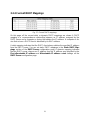
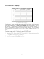
3.2.2. Current DHCP Mappings
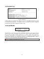
3.2.3. System Log
3.2.4. Link Monitor
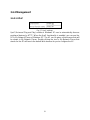
3.3. General Operations
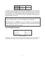
3.3.1. Specifying Operational Mode
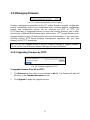
3.3.2. Changing Password
3.3.3. Managing Firmware
3.3.3.1. Upgrading Firmware by HTTP
3.3.3.2. Backing up and Restoring Configuration Settings by HTTP
3.3.3.3. Upgrading Firmware by TFTP
3.3.3.4. Backing up and Restoring Configuration Settings by TFTP
3.3.3.5. Resetting Configuration to Factory Defaults
3.4. Configuring TCP/IP Related Settings
3.4.1. Addressing
3.4.2. DHCP Server
3.4.2.1. Basic
3.4.2.2. Static DHCP Mappings
3.5. Configuring IEEE 802.11g-Related Settings
3.5.1. Communication
3.5.1.1. Basic
3.5.1.2. Link Integrity

vi
3.5.1.3. Association Control
3.5.1.4. AP Load Balancing
3.5.1.5. Wireless Distribution System
3.5.2. Security
3.5.2.1. Basic
3.5.2.2. MAC-Address-Based Access Control
3.5.3. IEEE 802.1x/RADIUS
3.6. Configuring Advanced Settings
3.6.1. Packet Filters
3.6.1.1. Ethernet Type Filters
3.6.1.2. IP Protocol Filters
3.6.1.3. TCP/UDP Port Filters
3.6.2. Management
3.6.2.1. UPnP
3.6.2.2. System Log
3.6.2.3. SNMP
Appendix A: Default Settings
Appendix B: Troubleshooting
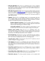
B-1: Wireless Settings Problems
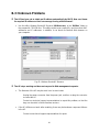
B-2: TCP/IP Settings Problems
B-3: Unknown Problems
Appendix C: Additional Information
C-1: Firmware Upgrade Using Xmodem Upgrade

1
1.
Introduction
1.1 Overview
The MIL-W2332G ShAir AccessG Pro Wireless Access Point/Bridge enables IEEE
802.11g or IEEE 802.11b client computers to access the resources on the Ethernet
network. With the sleek Web-based user interface and the included ShAir Wireless
Management Utility, a network administrator can easily and clearly manage the AP.
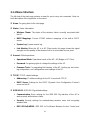
1.2 Features
• IEEE 802.11g
Operational modes
AP/Bridge. This mode provides both Access Point and Static LAN-to-LAN
Bridging functionality. The static LAN-to-LAN bridging function is supported
through Wireless Distribution System (WDS).
AP Client. This mode is for Dynamic LAN-to-LAN Bridging. The AP Client
automatically establishes bridge links with APs from any vendors.
RF type selection. The RF type of the WLAN interface can be configured to
work in IEEE 802.11b only, IEEE 802.11g only, or mixed mode (802.11g and
802.11b simultaneously).
64-bit and 128-bit WEP (Wired Equivalent Privacy). For authentication and
data encryption.
Enabling/disabling SSID broadcasts. When the AP is in AP/Bridge mode, the
administrator can enable or disable the SSID broadcasts functionality for secu-
rity reasons. When the SSID broadcasts functionality is disabled, a client com-
puter cannot connect to the AP with an “any” network name (SSID, Service Set
ID); the correct SSID has to be specified on client computers.
MAC-address-based access control. When the AP is in AP/Bridge mode, it
can be configured to block unauthorized wireless client computers based on
MAC (Media Access Control) addresses. The ACL (Access Control List) can be
downloaded from a TFTP server.

2
IEEE 802.1x/RADIUS. When the AP is in AP/Bridge mode, it can be configured
to authenticate wireless users and distribute encryption keys dynamically by
IEEE 802.1x Port-Based Network Access Control and RADIUS (Remote Au-
thentication Dial-In User Service).
WPA (Wi-Fi Protected Access). The AP supports the WPA standard proposed
by the Wi-Fi Alliance (http://www.wi-fi.org). Both WPA-PSK (Pre-Shared Key)
mode and full WPA mode are supported. WPA is composed of TKIP (Temporal
Key Integrity Protocol) and IEEE 802.1x and serves as a successor to WEP for
better WLAN security.
Repeater. When the AP is in AP/Bridge mode, it can communicate with other
APs or wireless bridges via WDS (Wireless Distribution System). Therefore, an
AP can wirelessly forward packets from wireless clients to another AP, and then
the later AP forwards the packets to the Ethernet network.
Antenna alignment assistance. The AP provides a WDS link quality in-
dicator via Wireless Network Manager to facilitate alignment of directional
antennas when deploying pairs of wireless bridges.
Link health monitoring. This feature enables the administrator to see if
the WDS links of the AP to other peer wireless bridges are working fine.
Wireless client isolation. When the AP is in AP/Bridge mode, wire-
less-to-wireless traffic can be blocked so that the wireless clients cannot see
each other. This capability can be used in hotspot applications to prevent wire-
less hackers from attacking other wireless users’ computers.
AP load balancing. Several APs can form a load-balancing group. Within a
group, wireless client associations and traffic load can be shared among the
APs. This function is available when the AP is in AP/Bridge mode.
Transmit power control. Transmit power of the AP’s RF module can be ad-
justed to change RF coverage of the AP.
Link integrity. When the AP is in AP/Bridge mode and its Ethernet LAN inter-
face is detected to be disconnected from the wired network, all currently associ-
ated wireless clients are disassociated by the AP and no wireless client can as-
sociate with it.
Association control. When the AP is in AP/Bridge mode, it can be configured
to deny association requests when it has served too many wireless clients or
traffic load is too heavy.
Associated wireless clients status. When the AP is in AP/Bridge mode, it can
show the status of all wireless clients that are associated with the AP.
Detachable antennas. The factory-mounted antennas can be replaced with

3
high-gain antennas for different purposes.
• DHCP client. The AP can automatically obtain an IP address from a DHCP server.
• DHCP server. The AP can automatically assign IP addresses to computers or other
devices by DHCP (Dynamic Host Configuration Protocol).
Static DHCP mappings. The administrator can specify static IP address to
MAC address mappings so that the specified IP addresses are always assigned
to the hosts with the specified MAC addresses.
Showing current DHCP mappings. Showing which IP address is assigned to
which host identified by an MAC address.
• Packet Filtering. The AP provides Layer 2, Layer 3, and Layer 4 filtering capabili-
ties.
• Firmware Tools
Firmware upgrade. The firmware of the AP can be upgraded in the following
methods:
Xmodem-based. Upgrading firmware over RS232.
TFTP-based. Upgrading firmware by TFTP (Trivial File Transfer Protocol).
HTTP-based. Upgrading firmware by HTTP (HyperText Transfer Proto-
col).
Configuration backup. The configuration settings of the AP can be backed up
to a file via TFTP or HTTP for later restoring.
Configuration reset. Resetting the configuration settings to factory-default
values.
• Management
Windows-based Wireless Network Manager for configuring, monitoring, and
diagnosing the local computer and neighboring APs. The management protocol
is MAC-based.
Web-based Network Manager for configuring and monitoring the AP via a Web
browser. The management protocol is HTTP (HyperText Transfer Proto-
col)-based.

4
SNMP. SNMP (Simple Network Management Protocol) MIB I, MIB II, IEEE
802.1d, IEEE 802.1x, and Private Enterprise MIB are supported.
UpnP. The AP responds to UpnP discovery messages so that a Windows XP
user can locate the AP in My Network Places and use a Web browser to config-
ure it.
Telnet. The user is enabled to manage the AP by Telnet.
System log. For system operational status monitoring.
Local log. System events are logged to the on-board RAM of the AP and
can be viewed using a Web browser.
Remote log by SNMP trap. Systems events are sent in the form of
SNMP traps to a remote SNMP management server.
• Power over Ethernet. Power-over-Ethernet is supported, power has to be sent via
data pairs 1:2/3:6
• Hardware Watchdog Timer. If the firmware gets stuck in an invalid state, the hard-
ware watchdog timer will detect this situation and restart the AP. This way, the AP
can provide continuous services.
1.3 LED Definitions
There are several LED indicators on the housing of the AP. They are defined as follows:
• Alive: Blinks when the AP is working normally.
• RF: IEEE 802.11g interfaces activity
• LAN: Ethernet LAN interface activity
• Power: Power

5
2.
First-Time Installation and Configuration
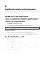
2.1 Selecting a Power Supply Method
Optionally, the AP can be powered by the supplied power adapter or PoE (Power over
Ethernet). The AP automatically selects the suitable one depending on your decision.
To power the AP by the supplied power adapter:
1. Plug the power adapter to an AC socket.
2. Plug the connector of the power adapter to the power jack of the AP.
NOTE: This product is intended to be power-supplied by a Listed Power Unit, marked
“Class 2” or “LPS” and output rated “5V DC, 1 A minimum” or equivalent statement.
To power the AP by PoE:
1. Plug one connector of an Ethernet cable to an available port of a PoE hub.
2. Plug the other connector of the Ethernet cable to the LAN/CONFIG port of the AP.
2.2 Mounting the AP on a Wall
The AP is wall-mountable.
1. Stick the supplied sticker for wall-mounting.
2. Use a 6.5mm driller to drill a 25mm-deep hole at each of the cross marks.
3. Plug in a supplied plastic conical anchor in each hole.
4. Screw a supplied screw in each plastic conical anchor for a proper depth so that
the wireless AP can be hung on the screws.
5. Hang the wireless AP on the screws.

6
Fig. 1. Mounting the AP on a wall.
2.3 Preparing for Configuration
For you to configure an AP, a managing computer with a Web browser is needed. For
first-time configuration of an AP, an Ethernet network interface card (NIC) should have
been installed in the managing computer. For maintenance-configuration of a deployed
AP, either a wireless computer or a wired computer can be employed as the managing
computer.
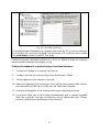
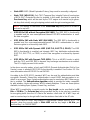
NOTE: If you are using the browser, Opera, to configure an AP, click the menu item
File, click Preferences…, click File types, and edit the MIME type, text/html, to add a
file extension “.sht” so that Opera can work properly with the Web management pages
of the AP.
Since the configuration/management protocol is HTTP-based, you have to make sure
that the IP address of the managing computer and the IP address of the managed
AP are in the same IP subnet (the default IP address of an AP is Error! Reference
source not found. and the default subnet mask is 255.255.255.0.)

7
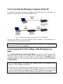
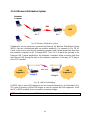
2.3.1 Connecting the Managing Computer and the AP
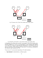
To connect the Ethernet managing computer and the managed AP for first-time con-
figuration, you have two choices as illustrated in Fig. 2.
Managing
Computer
Normal
Ethernet
cable
ShAir AccessG
Pro AP
Normal
Ethernet
cable
Ethernet
Hub/Switch
Cross-ove
r
Ethernet
cable
Fig. 2. Connecting a managing computer and an AP via Ethernet.
You can use either a cross-over Ethernet cable (included in the package) or a
switch/hub with 2 normal Ethernet cables.
NOTE: One connector of the Ethernet cable must be plugged into the LAN/CONFIG
Ethernet jack of the AP for configuration.
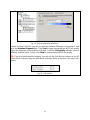
2.3.2 Changing the TCP/IP Settings of the Managing Com-
puter
Use the Windows Network Control Panel Applet to change the TCP/IP settings of the
managing computer, so that the IP address of the computer and the IP address of the
AP are in the same IP subnet. Set the IP address of the computer to 192.168.1.xxx (the
default IP address of an AP is Error! Reference source not found.) and the subnet mask
to 255.255.255.0.
NOTE: For some versions of Windows, the computer needs to be restarted for the
changes of TCP/IP settings to take effect.
TIP: After you have connected the managing computer and the AP via Ethernet, you
can install Wireless Network Manager on the managing computer and use it to config-
ure the AP without being concerned about the TCP/IP settings of the managing com-
puter. Refer to the on-line help of Wireless Network Manager for more information.

8
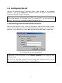
2.4 Configuring the AP
After the IP addressing issue is resolved, launch a Web browser on the managing
computer. Then, go to “http://Error! Reference source not found.” to access the
Web-based Network Manager Start page.
TIP: For maintenance configuration of an AP, the AP can be reached by its host name
using a Web browser. For example, if the AP is named “AP”, you can use the URL
“http://AP” to access the Web-based Network Manager of the AP.
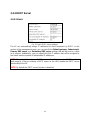
2.4.1 Entering the User Name and Password
Before the start page is shown, you will be prompted to enter the user name and pass-
word to gain the right to access the Web-based Network Manager. For first-time con-
figuration, use the default user name “root” and default password “root”, respectively.
Fig. 3. Entering the user name and password.
NOTE: It is strongly recommended that the password be changed to other value for se-
curity reasons. On the start page, click the General, Password link to change the value
of the password.
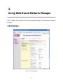
TIP: Since the start page shows the current settings and status of the AP, it can be
saved or printed within the Web browser for future reference.

9
Fig. 4. The Start page.
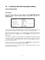
2.4.2 Step 1: Selecting an Operational Mode
Fig. 5. Operational modes settings.
Go to the General, Operational Mode section, select an operational mode and click
Save at the bottom of this page, and then you are brought back to the start page.
The AP supports 2 operational modes:
• AP/Bridge. This mode provides both Access Point and Static LAN-to-LAN Bridging
functionality. The static LAN-to-LAN bridging function is supported through Wireless
Distribution System (WDS).

10
• AP Client. This mode is for Dynamic LAN-to-LAN Bridging. The AP Client auto-
matically establishes bridge links with APs from any vendors.
In either mode, the AP forwards packets between its Ethernet interface and wireless in-
terface for wired hosts on the Ethernet side and wireless host(s) on the wireless side.
There are 2 types of wireless links as specified by the IEEE 802.11 standard.
• STA-AP. This type of wireless link is established between an IEEE 802.11 Station
(STA) and an IEEE 802.11 Access Point (AP). A STA is usually a client computer
(PC or PDA) with a WLAN network interface card (NIC). The AP Client mode is ac-
tually an STA.
• WDS. This type of wireless link is established between two IEEE 802.11 APs. Wire-
less packets transmitted along the WDS link comply with the IEEE 802.11 WDS
(Wireless Distribution System) format at the link layer.
The relationships among the operational modes and the wireless link types are shown
in the following table:
Table 1. Operational modes vs. wireless link types.
AP/Bridge AP Client
AP/Bridge
WDS STA-AP
AP Client
STA-AP
To establish a static bridge link based on WDS, the AP/bridges at both end of the WDS
link must be manually configured with each other’s MAC addresses (see Section 0 for
more information). To establish a dynamic bridge link between an AP and an AP Client,
both devices have to be configured with the same SSID and WEP settings. The AP Cli-
ent automatically scans for any AP that is using the matched SSID and establishes a
bridge link with the scanned AP.
NOTE: Although it’s more convenient to use dynamic bridging, it has a limitation—the
AP Client only can forward TCP/IP packets between its wireless interface and Ethernet
interface; other type of traffic (such as IPX and AppleTalk) is not forwarded.
TIP: When the AP is configured to be in AP Client, it can be used as an
Ethernet-to-wireless network adapter. For example, a notebook computer equipped with
an Ethernet adapter can be connected to this device with a crossover Ethernet cable for
wireless connectivity to another access point.

11
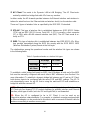
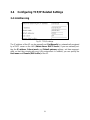
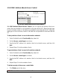
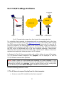
2.4.3 Step 2: Configuring TCP/IP Settings
Fig. 6. TCP/IP settings.
Go to the TCP/IP, Addressing section to configure IP address settings. The IP address
can be manually set or automatically assigned by a DHCP server on the LAN. If you are
manually setting the IP address, Subnet mask, and Default gateway settings, set
them appropriately, so that they comply with your LAN environment. In addition, you can
specify the Host name and Domain (DNS suffix) of the AP.
When you are finished, click Save at the bottom of this page, and then you are brought
back to the start page.
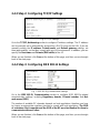
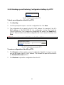
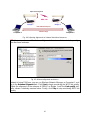
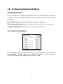
2.4.4 Step 3: Configuring IEEE 802.11 Settings
Fig. 7. IEEE 802.11g communication settings.
Go to the IEEE 802.11, Communication section to configure IEEE 802.11g-related
communication settings, including Regulatory domain, Channel number, and Net-
work name (SSID).
The number of available RF channels depends on local regulations; therefore you have
to choose an appropriate regulatory domain to comply with local regulations. The SSID
of a wireless client computer and the SSID of the AP must be identical for them to
communicate with each other.
When you are finished, click Save at the bottom of this page, and then you are brought
back to the start page.

12
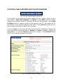
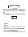
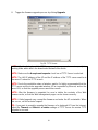
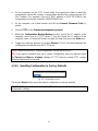
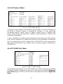
2.4.5 Step 4: Reviewing and Applying Settings
Fig. 8. Settings changes are highlighted in red.
On the start page, you can review all the settings you have made. Changes are high-
lighted in red. If they are OK, click Restart to restart the AP for the new settings to take
effect.
NOTE: About 7 seconds are needed for the AP to complete its restart process.
Page is loading ...
Page is loading ...
Page is loading ...
Page is loading ...
Page is loading ...
Page is loading ...
Page is loading ...
Page is loading ...
Page is loading ...
Page is loading ...
Page is loading ...
Page is loading ...
Page is loading ...
Page is loading ...
Page is loading ...
Page is loading ...
Page is loading ...
Page is loading ...
Page is loading ...
Page is loading ...
Page is loading ...
Page is loading ...
Page is loading ...
Page is loading ...
Page is loading ...
Page is loading ...
Page is loading ...
Page is loading ...
Page is loading ...
Page is loading ...
Page is loading ...
Page is loading ...
Page is loading ...
Page is loading ...
Page is loading ...
Page is loading ...
Page is loading ...
Page is loading ...
Page is loading ...
Page is loading ...
Page is loading ...
Page is loading ...
Page is loading ...
Page is loading ...
Page is loading ...
Page is loading ...
Page is loading ...
Page is loading ...
Page is loading ...
Page is loading ...
-
 1
1
-
 2
2
-
 3
3
-
 4
4
-
 5
5
-
 6
6
-
 7
7
-
 8
8
-
 9
9
-
 10
10
-
 11
11
-
 12
12
-
 13
13
-
 14
14
-
 15
15
-
 16
16
-
 17
17
-
 18
18
-
 19
19
-
 20
20
-
 21
21
-
 22
22
-
 23
23
-
 24
24
-
 25
25
-
 26
26
-
 27
27
-
 28
28
-
 29
29
-
 30
30
-
 31
31
-
 32
32
-
 33
33
-
 34
34
-
 35
35
-
 36
36
-
 37
37
-
 38
38
-
 39
39
-
 40
40
-
 41
41
-
 42
42
-
 43
43
-
 44
44
-
 45
45
-
 46
46
-
 47
47
-
 48
48
-
 49
49
-
 50
50
-
 51
51
-
 52
52
-
 53
53
-
 54
54
-
 55
55
-
 56
56
-
 57
57
-
 58
58
-
 59
59
-
 60
60
-
 61
61
-
 62
62
-
 63
63
-
 64
64
-
 65
65
-
 66
66
-
 67
67
-
 68
68
-
 69
69
-
 70
70


Milan Technology ShAir AccessG Pro MIL-W2332G User manual
- Category
- WLAN access points
- Type
- User manual
- This manual is also suitable for
Ask a question and I''ll find the answer in the document
Finding information in a document is now easier with AI
Related papers
Other documents
-
 Alloy Computer Products WDS2454AP User manual
-
SENAO SL-2511SR User manual
-
MiLAN MIL-W2331G User manual
-
 Moxa Technologies Network Hardware MOXA AirWorks User manual
-
Moxa AWK-1100 User manual
-
National Instruments WAP-3711 User manual
-
SMC Networks SMC2586W-G User manual
-
-
Epson IWE3200-H User manual
-

