Craftsman 919167270 Owner's manual
- Category
- Air compressors
- Type
- Owner's manual
This manual is also suitable for

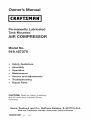
Owner's Manual
ICRAFTSMFINI
Permanently Lubricated
Tank Mounted
AiR COMPRESSOR
= Safety Guidelines
= Assembly
= Operation
= Maintenance
= Service and Adjustments
= Troubleshooting
= Repair Parts
CAUTION; Read the Safety Guidelines
and All Instructions Carefully Before
Operating.
Sears, Roebuck and Co., Hoffman Estates, IL 60179 U.S.A.
Visit our Craftsman website: www.sears.com/craftsman
1000001267 R_v.o 4/4/07

WARRANTY ................................................ 2
SPECiFiCATiON CHART ..................................... 3
SAFETY GUiDELiNES ...................................... 3-8
GLOSSARY ................................................ 9
ACCESSORIES ............................................. 9
DUTY CYCLE .............................................. 9
ASSEMBLY ............................................... 10
iNSTALLATiON ......................................... 11-12
OPERATION ........................................... 13-15
MAINTENANCE ............................................ 16
SERVICE AND ADJUSTMENTS ............................ 17-18
STORAGE ................................................ 18
TROUBLESHOOTING GUIDE ............................. 19-21
REPAIR PARTS ......................................... 22-25
ESPANOL .............................................. 26-46
REPAIR PROTECTION AGREEMENTS ......................... 47
HOW TO ORDER REPAIR PARTS ...................... back cover
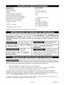
FULL ONE YEAR WARRANTY AiR COMPRESSOR
If this CRAFTSMAN Air Compressor fails due to a defect in material or
workmanship within one year from the date of purchase, Sears will at
its option repair or replace it free of charge. Contact your nearest Sears
Service Center (1-800-4-MY-HOME ®) to arrange for repair, or return the Air
Compressor to the place of purchase for replacement.
If this Air Compressor is used for commercial or rental purposes, this warranty
applies for only ninety days from the date of purchase.
This warranty gives you specific legal rights and you may have other rights
which vary from state to state.
Sears, Roebuck and Co., Dept. 817WA, Hoffman Estates, IL 60179
1000001267 2-ENG

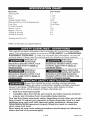
Model Ne. 919-187270
*Running HP 1.1
Bore 1-7/8"
Stroke 1-1/4"
Voltage-Single Phase 120V
Minimum Branch Circuit Requirement 15 amps
Fuse Type Time Delay
Air Tank Capacity 17
Approx. Cut-In 120
Approx. Cut-out 150
*SCFM @40 psig 4.3
*SCFM @90 psig 3.3
*(Tested per ISO 1217)
Refer to Glossary for abbreviations.
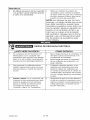
This manual contains information that is important for you to know and under-
stand. This information relates to protecting YOUR SAFETY and PREVENTING
EQUIPMENT PROBLEMS. To help you recognize this information, we use the
symbols below. Please read the manual and pay attention to these symbols.
_ Indicates an
imminently
hazardous situation which, if not
avoided, will result in death or
serious iniury.
_ Indicates a
potentially
hazardous situation which, if not
avoided, could result in death or
serious
_ Indicates a
potentially
hazardous situation which, if not
avoided, _ result in minor or
moderate iniurV.
_Used without the
__ safety alert symbol
indicates a potentially hazardous
situation which, if not avoided, may
result in property damag#_.
0
_Some dust created by power sanding, sawing, grinding,
drilling, and other construction activities contains chemicals
known to the State of California to cause cancer, birth defects or other
reproductive harm. Some example of these chemicals are:
• lead from lead-based paints
• crystalline silica from bricks and cement and other masonry products
arsenic and chromium from chemically=treated lumber
Your risk from these exposures varies, depending on how often you do this
type of work. To reduce your exposure to these chemicals: work in a well
ventilated area, and work with approved safety equipment, always wear
OSHA/MSHA/NIOSH approved, properly fitting face mask or respirator
when using such tools.
When using air tools, basic safety precautions should always be followed to
reduce the risk of of personal injury.
3-ENG 1000001267

_This product contains chemicals, including lead, known to
the State of California to cause cancer, and birth defects or
other reproductive harm. Wash hands after handling.
Do not operate this unit until you read and _-_
understand this instruction manual for safety,
operation and maintenance instructions.
SAVE THESE iNSTRUCTiONS
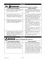
___ RISK OF EXPLOSION OR FIRE
WHAT CAN HAPPEN
• Itis normal for electrical contacts
within the motor and pressure
switch to spark.
Ifelectrical sparks from compressor
come into contact with flammable
vapors, they may ignite, causing fire
or explosion.
Restricting any of the compressor
ventilation openings will cause seri-
ous overheating and could cause
fire.
Unattended operation of
this product could result in per-
sonal injury or property damage. To
reduce the risk of fire, do not allow
the compressor to operate unat-
tended.
NOW TO PREVENT iT
• Always operate the compressor in a
well ventilated area free of combus-
tible materials, gasoline, or solvent
vapors.
Ifspraying flammable materials,
locate compressor at least 20 feet
(6.1 m) away from spray area. An
additional length of air hose may be
required.
Store flammable materials in a
secure location away from com-
pressor.
Never place objects against or on
top of compressor.
Operate compressor in an open
area at least 12" (304.8 mm) away
from any wall or obstruction that
would restrict the flow of fresh air to
the ventilation openings.
Operate compressor in a clean, dry
well ventilated area. Do not operate
unit indoors or in any confined area.
Always remain in attendance
with the product when it is
operating.
Always turn off and unplug unit
when not in use.
1000001267 4-ENG

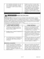
__ RISK TO BREATHING (ASPHYXiATiON)
HOW TO PREVENT iT
= • Air obtained directly from the com-
pressor should never be used to
supply air for human consumption.
In order to use air produced by this
compressor for breathing, suitable
filters and in-line safety equipment
must be properly installed. In-line
filters and safety equipment used
in conjunction with the compressor
must be capable d treating air to all
applicable local and federal codes
prior to human consumption.
• Sprayed materials such as paint, • Work in an area with good cross
paint solvents, paint remover, insec- ventilation. Read and follow the
ticides, weed killers, may contain safety instructions provided on the
harmful vapors and poisons, label or safety data sheets for the
materials you are spraying. Always
use certified safety equipment:
OSHA!MSHA!NIOSH respiratory
protection designed for use with
your specific application.
RiSKorBURSTING
WHAT CAN HAPPEN
The compressed air directly from
your compressor is not safe for
breathing. The air stream may con-
tain carbon monoxide, toxic vapors,
or solid particles from the air tank.
Breathing these contaminant's can
cause serious injury or death.
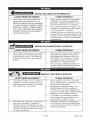
Air Tank: The air tank on your Air Compressor is designed and may be UM coded
(for units with air tanks greater than 6 inch diameter) according to ASME Section VIII,
Div. 1 rules. All pressure vessels should be inspected once every two years. To find
your state pressure vessels inspector, look under the Division of Labor and Industries
in the government section of a phone book.
The following conditions could lead to a weakening of the air tank, and result in a
violent air tank explosion:
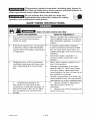
WHAT CAN HAPPEN HOW TO PREVENT iT
Failure to properly drain condensed • Drain air tank daily or after each
water from air tank, causing rust use. If air tank develops a leak,
and thinning of the steel air tank. replace it immediately with a new air
tank or replace the entire compres-
sor.
Modifications or attempted repairs • Never drill into, weld, or make any
to the air tank. modifications to the air tank or its
attachments. Never attempt to
repair a damaged or leaking air
tank. Replace with a new air tank.
5-ENG 1000001267

• Unauthorized modifications to the • The air tank is designed to with-
safety valve or any other compo- stand specific operating pressures.
nents which control air tank pres- Never make adjustments or parts
sure. substitutions to alter the factory set
operating pressures.
o
Attachments & accessories:
Exceeding the pressure rating of
air tools, spray guns, air operated
accessories, tires, and other inflata-
bles can cause them to explode or
fly apart, and could result in serious
injury.
Tires:
Follow the equipment manufactur-
ers recommendation and never
exceed the maximum allowable
pressure rating of attachments.
Never use compressor to inflate
small low pressure objects such as
children's toys, footballs, basket-
balls, etc.
Over inflation of tires could result in _ Use a tire pressure gauge to check
serious injury and property damage, the tires pressure before each use
and while inflating tires; see the tire
sidewall for the correct tire pressure.
NOTE: Air tanks, compressors and simi-
larequipment used to inflate tires can fill
small tires similar to these very rapidly.
Adjust pressure regulator on air supply to
no more than the rating of the tire pres-
sure. Add air in small increments and
frequently use the tire gauge to prevent
over inflation.
__ RISK OF ELECTRICAL SHOCK
WHAT CAN HAPPEN
Your air compressor is powered by
electricity. Like any other electrically
powered device, If it is not used
properly it may cause electric
shock.
Repairs attempted by unqualified
personnel can result in serious
injury or death by electrocution.
Electrical Grounding: Failure to
provide adequate grounding to
this product could result in serious
injury or death from electrocution.
Refer to "Grounding Instructions"
paragraph in the "Installation"
section.
HOW TO PREVENT IT
Never operate the compressor
outdoors when it is raining or in wet
conditions.
Never operate compressor with
protective covers removed or
damaged.
Any electrical wiring or repairs
required on this product should be
performed by authorized service
center personnell in accordance
with national and local electrical
codes.
Make certain that the electrical
circuit to which the compressor
is connected provides proper
electrical grounding, correct voltage
and adequate fuse protection.
1000001267 6-ENG

__ RiSK FROM FLYING OBJECTS
WHAT CAN HAPPEN HOW TO PREVENT iT
• The compressed air stream can • Always wear certified safety equip-
cause soft tissue damage to merit: ANSI Z87.1 eye protection
exposed skin and can propel dirt, (CAN/CSA Z94.3) with side shields
chips, loose particles, and small when using the compressor.
objects at high speed, resulting in • Never point any nozzle or sprayer
property damage or personal injury, toward any part of the body or at
other people or animals.
Always turn the compressor off
and bleed pressure from the air
hose and air tank before attempt-
ing maintenance, attaching tools or
accessories.
__ RiSK OF HOT SURFACES
WHAT CAN HAPPEN HOW TO PREVENT iT
= Touching exposed metal such as • Never touch any exposed metal
the compressor head, engine head, parts on compressor during or
engine exhaust or outlet tubes, can immediately after operation.
result in serious burns. Compressor will remain hot for
several minutes after operation.
Do not reach around protective
shrouds or attempt maintenance
until unit has been allowed to cool.
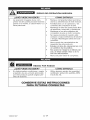
___ RiSK FROM MOVING PARTS
WHAT CAN HAPPEN
Moving parts such as the pulley, fly-
wheel, and belt can cause serious
injury if they come into contact with
you or your clothing.
Attempting to operate compressor
with damaged or missing parts or
attempting to repair compressor
with protective shrouds removed
can expose you to moving parts
and can result in serious injury.
o
o
HOW TO PREVENT iT
Never operate the compressor with
guards or covers which are dam-
aged or removed.
Keep your hair, clothing, and gloves
away from moving parts. Loose
clothes, jewelry, or long hair can be
caught in moving parts.
Air vents may cover moving parts
and should be avoided as well.
Any repairs required on this product
should be performed by autHorized
service center personnell.
7-ENG 1000001267

[__ RISK OF UNSAFE OPERATION
WHAT CAN HAPPEN HOW TO PREVENT IT
• Unsafe operation of your air com- • Review and understand all instruc-
pressor could lead to serious injury tions and warnings in this manual.
or death to you or others. • Become familiar with the operation
and controls of the air compressor.
Keep operating area clear of all per-
sons, pets, and obstacles.
Keep children away from the air
compressor at all times.
Do not operate the product when
fatigued or under the influence of
alcohol or drugs. Stay alert at all
times.
Never defeat the safety features of
this product.
Equip area d operation with afire
extinguisher.
Do not operate machine with miss-
ing, broken, or unauthorized parts.
[Q]_ RiSK FROM NOISE
WHAT CAN HAPPEN
Under some conditions and dura-
tion of use, noise from this product
may contribute to hearing loss.
HOW TO PREVENT IT
Always wear certified safety equip-
ment: ANSI $12.6 ($3.19) hearing
protection.
SAVE THESE INSTRUCTIONS
FOR FUTURE USE
1000001267 8-ENG

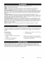
Become familiar with these terms before operating the unit.
CFM: Cubic feet per minute.
SCFM: Standard cubic feet per minute; a unit of measure of air delivery.
PSIG: Pounds per square inch gauge; a unit of measure of pressure.
Code Certification: Products that bear one or more of the following marks: UL,
CUL, ETL, CETL, have been evaluated by OSHA certified independent safety
laboratories and meet the applicable Underwriters Laboratories Standards for
Safety.
Cut-In Pressure: While the motor is off, air tank pressure drops as you
continue to use your accessory. When the tank pressure drops to a certain low
level the motor will restart automatically. The low pressure at which the motor
automatically restarts is called "cut-in" pressure.
Cut-Out Pressure: When an air compressor is turned on and begins to run,
air pressure in the air tank begins to build. It builds to a certain high pressure
before the motor automatically shuts off, protecting your air tank from pressure
higher than its capacity. The high pressure at which the motor shuts off is
called "cut-out" pressure.
Branch Circuit: Circuit carrying electricity from electrical panel to outlet.
This unit is capable of powering the following Accessories. The accessories are
available through the current Power and Hand Tool Catalog or full-line Sears
stores.
Accessories
• in Line Filter
Tire Air Chuck
Quick Connector Sets (various
sizes)
Air Pressure Regulators
Oil Fog Lubricators
Air Hose: 1/4", 3/8" or 1/2" I.D. in
various lengths
Refer to the selection chart located
on the unit to select the tools this unit
is capable of powering.
This air compressor pump is capable of running continuously. However, to
prolong the life of your air compressor, it is recommended that a 50%-75%
average duty cycle be maintained; that is, the air compressor pump should not
run more than 30-45 minutes in any given hour.
9-ENG 1000001267

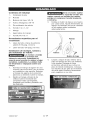
Contents of Carton
1 - Air Compressor
2- Wheels
2 - Shoulder Bolts, 3/8-16
2 - Hex Nuts, 3/8-16
2 - Molded Foot Bumpers
2 - Screws, 1/4 x 1-1/2
1 Handle
1 - Handle Grip
2 - Screws, #10-16 x 1
Tools Required for
Assembly
1 - 9/16" socket or open end
wrench
1 - 3/8" socket
Installing Handles,
Wheels, and Molded Foot
Bumpers
_The wheels
and handle
do not provide adequate clearance,
stability or support for pulling the
unit up and down stairs or steps.
The unit must be lifted, or pushed
up a ramp.
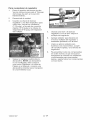
1. Submerge handle grip into warm
soapy water to make installation
easier. Remove handle grip from
soapy water and slide onto
handle.
2,
Slide handle through holes in
compressor saddle onto tabs.
Secure with screws, one on each
side.
_lt will be necessary
to brace or
support one side of the outfit when
installing the wheels because the
compressor will have a tendency to
tip over.
3. Install one shoulder bolt
and one nut for each wheel.
Tighten securely. The outfit
will sit level if the wheels are
properly installed.
\\\
\
Wheel
Nut
/
4,
Shoulder Belt
Clean and dry underside of
air tank leg opposite wheels.
Remove the protective strip from
the adhesive backed molded
foot bumpers. Attach the foot
bumpers to the bottom of leg
on each end. Press firmly into
place.
Molded
1000001267 10-ENG

HOW TO SET UP YOUR UNiT iMPORTANT: The outlet being used
Location of the Air Compressor
Locate the air compressor in a
clean, dry and well ventilated area.
The air compressor should be
located at least 12" away from the
wall or other obstructions that will
interfere with the flow of air. The
air compressor pump and shroud
are designed to allow for proper
cooling. The ventilation openings
on the compressor are necessary
to maintain proper operating
temperature. Do not place rags or
other containers on or near these
openings.
GROUNDING iNSTRUCTIONS
Risk of Electrical
Shock. In the
event of a short circuit, grounding
reduces the risk of shock by
providing an escape wire for
the electric current. This air
compressor must be properly
grounded.
The portable air compressor is
equipped with a cord having a
grounding wire with an appropriate
grounding plug (see following
illustrations). The plug must be used
with an outlet that has been installed
and grounded in accordance with all
local codes and ordinances.
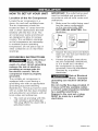
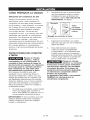
1. The cord set and plug with this
unit contains a grounding pin.
This plug MUST be used with a
grounded outlet.
must be installed and grounded in
accordance with all local codes and
ordinances.
Make sure the outlet being used
has the same configuration
as the grounded plug. DO
NOT USE AN ADAPTER. See
illustration.
Inspect the plug and cord before
each use. Do not use if there are
signs of damage.
Ifthese grounding instructions
are not completely understood,
or if in doubt as to whether
the compressor is properly
grounded, have the installation
checked by a qualified
electrician.
Risk of Electrical
_ Shock. improper
grounding can result in electrical
shock.
Do not modify the plug provided, if
it does not fit the available outlet,
a correct outlet should be installed
by a qualified electrician.
Repairs to the cord set or plug
MUST be made by a qualified
electrician.
11-ENG 1000001267

Extension Cords
Using extension cords is not
recommended. The use of extension
cords will cause voltage to drop
resulting in power loss to the motor
and overheating.
Instead of using an extension cord,
increase the working reach of the
air hose by attaching another length
of hose to its end. Attach additional
lengths of hose as needed.
If an extension cord must be used,
be sure it is:
• a 3-wire extension cord that has
a 3-blade grounding plug, and a
3-slot receptacle that will accept
the plug on the product
in good condition
no longer than 50 feet
12 gauge (AWG) or larger. (Wire
size increases as gauge number
decreases. 10 AWG and 8 AWG
may also be used. DO NOT USE
14 OR 16 AWG.)
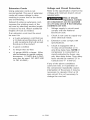
Voltage and Circuit Protection
Refer to the specification chart for the
voltage and minimum branch circuit
requirements.
_Risk of Unsafe
Operation. Certain
air compressors can be operated
on a 15 amp circuit if the following
conditions are met.
1. Voltage supply to circuit must
comply with the National
Electrical Code.
2. Circuit is not used to supply any
other electrical needs.
3. Extension cords comply with
specifications.
4. Circuit is equipped with a
15 amp circuit breaker or 15
amp time delay fuse. NOTE: If
compressor is connected to a
circuit protected by fuses, use
only time delay fuses. Time delay
fuses should be marked "D" in
Canada and "T" in the US.
If any of the above conditions
cannot be met, or if operation of
the compressor repeatedly causes
interruption of the power, it may be
necessary to operate it from a 20
amp circuit. It is not necessary to
change the cord set.
1000001267 12-ENG

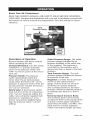
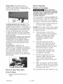
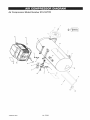
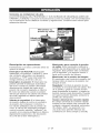
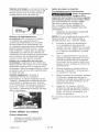
Know Your Air Compressor
READ THIS OWNER'S MANUAL AND SAFETY RULES BEFORE OPERATING
YOUR UNIT. Compare the illustrations with your unit to familiarize yourself with
the location of various controls and adjustments. Save this manual for future
reference.
Tank
Pressure Gauge
Safety
Valve
Body
Description of Operation
Become familiar with these controls
before operating the unit.
On/Auto/Off Switch: Turn this switch
"ON/AUTO" to provide automatic
power to the pressure switch and
"OFF" to remove power at the end of
each use.
Pressure Switch: The pressure
switch automatically starts the
motor when the air tank pressure
drops below the factory set "cut-in"
pressure. It stops the motor when the
air tank pressure reaches the factory
set "cut-out" pressure.
Safety Valve: If the pressure switch
does not shut off the air compressor
at its "cut-out" pressure setting, the
safety valve will protect against high
pressure by "popping out" at its
factory set pressure (slightly higher
than the pressure switch "cut-out"
setting).
Outlet Pressure Gauge: The outlet
pressure gauge indicates the air
pressure available at the outlet side
of the regulator. This pressure is
controlled by the regulator and is
always less than or equal to the tank
pressure.
Tank Pressure Gauge: The tank
pressure gauge indicates the reserve
air pressure in the tank.
Regulator: Controls the air pressure
shown on the outlet pressure
gauge. Pull the knob out and turn
clockwise to increase pressure
and counterclockwise to decrease
pressure. When the desired pressure
is reached push knob in to lock in
place.
Universal Quick-Connect Body:
The universal quick-connect body
accepts the three most popular styles
of quick-connect plugs- Industrial,
automotive (Tru-flate), and ARO. One
hand push-to-connect operation
makes connections simple and easy.
13-ENG 1000001267

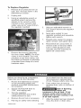
Drain Valve: The drain valve is
located at the base of the air tank
and is used to drain condensation at
the end of each use.
Drain
Valve
Cooling System (not shown): This
compressor contains an advanced
design cooling system. At the heart of
this cooling system is an engineered
fan. It is perfectly normal for this fan
to blow air through the vent holes
in large amounts. You know that the
cooling system is working when air is
being expelled.
Air Compressor Pump (not shown):
Compresses air into the air tank.
Working air is not available until the
compressor has raised the air tank
pressure above that required at the
air outlet.
Check Valve: When the air
compressor is operating, the check
valve is "open", allowing compressed
air to enter the air tank. When the
air compressor reaches "cut-out"
pressure, the check valve "closes",
allowing air pressure to remain inside
the air tank.
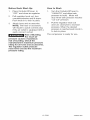
How to Use Your Unit
How to Stop:
1. Set the On/Auto/Off lever to
"OFF".
Before Starting
Break-in Procedure
_Risk of Unsafe
Operation. Serious
damage may result if the following
break-in instructions are not
closely followed.
This procedure is required before the
air compressor is put into service and
when the check valve or a complete
compressor pump has been replaced.
1. Make sure the On/Auto/Off lever
is in the "OFF" position.
NOTE: Pull coupler back until it clicks
to prevent air from escaping through
the quick connect.
2. Plug the power cord into the
correct branch circuit receptacle.
(Refer to Voltage and Circuit
Protection paragraph in the
Installation section of this
manual.)
3. Open the drain valve fully
(counter-clockwise) to permit
air to escape and prevent air
pressure build up in the air tank
during the break-in period.
4. Move the On/Auto/Off lever
to "ON/AUTO" position. The
compressor will start.
5. Run the compressor for 15
minutes. Make sure the drain
valve is open and there is
minimal air pressure build-up in
tank.
6. After 15 minutes, close the drain
valve (clockwise). The air receiver
will fill to "cut-out" pressure and
the motor will stop.
The compressor is now ready for use.
1000001267 14-ENG

Before Each Start-Up:
1. Place On/Auto/Off lever to
"OFF" and close air regulator.
2. Pull regulator knob out, turn
counterclockwise until it stops.
Push knob in to lock in place.
3. Attach hose and accessories.
NOTE: The hose or accessory
will require a quick connect plug
if the air outlet is equipped with a
quick connect socket.
_Risk of Bursting.
Too much air
pressure causes a hazardous
risk of bursting. Check the
manufacturer's maximum pressure
rating for air tools and accessories.
The regulator outlet pressure
must never exceed the maximum
pressure rating.
How to Start:
1. Turn the On/Auto/Off lever to
"ON/AUTO" and allow tank
pressure to build. Motor will
stop when tank pressure reaches
"cut-out" pressure.
2. Pull the regulator knob out
and turn clockwise to increase
pressure. When the desired
pressure is reached push knob in
to lock in place.
The compressor is ready for use.
15-ENG 1000001267

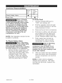
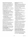
Customer Responsibilities
Before Daily
each or after
each
Jse
use
3heck Safety Valve O
Drain Tank ®
_Bisk of Unsafe
Operation. Unit
cycles automatically when power
is on. When servicing, you may
be exposed to voltage sources,
compressed air, or moving parts.
Before servicing unit unplug or
disconnect electrical supply to
the air compressor, bleed tank
of pressure, and allow the air
compressor to cool.
NOTE: See Operation section for the
location of controls.
To Check Safety Valve
_Bisk of Bursting.
If the safety valve
does not work properly, over-
pressurization may occur, causing
air tank rupture or an explosion.
1. Before starting compressor, pull
the ring on the safety valve to
make sure that the safety valve
operates freely. If the valve
is stuck or does not operate
smoothly, it must be replaced
with the same type of valve.
To Drain Tank
1. Set the On/Auto/Off lever to
"OFF" and unplug unit.
2. Pull the regulator knob out and
turn counterclockwise to set the
outlet pressure to zero.
3. Remove the air tool or accessory.
4. Pull ring on safety valve allowing
air to bleed from the tank until
tank pressure is approximately
20 psi. Release safety valve ring.
5. Drain water from air tank by
opening drain valve (counter-
clockwise) on bottom of tank.
_Biek of Bursting.
Water will
condense in the air tank. if not
drained, water will corrode and
weaken the air tank causing a risk
of air tank rupture.
6. After the water has been drained,
close the drain valve (clockwise).
The air compressor can now be
stored.
NOTE: If drain valve is plugged,
release all air pressure. The valve
can then be removed, cleaned, the
reinstalled.
1000001267 16-ENG

ALL MAINTENANCE AND REPAIR
OPERATIONS NOT LISTED MUST
BE PERFORMED BY TRAINED
SERVICE TECHNiCiAN.
_Risk of Unsafe
Operation. Unit
cycles automatically when power
is on. When servicing, you may
be exposed to voltage sources,
compressed air, or moving parts.
Before servicing unit unplug or
disconnect electrical supply to
the air compressor, bleed tank
of pressure, and allow the air
compressor to cool.
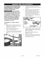
To Replace or Clean Check
Valve
1. Release all air pressure from air
tank. See "To Drain Tank" in the
Maintenance section.
2. Set the On/Auto/Off lever to
"OFF" and unplug unit.
3. Loosen the nut on the outlet tube
and move the outlet tube to the
side.
4,
5,
Unscrew the check valve (turn
counterclockwise) using a socket
wrench.
Make sure the valve disc moves
freely inside the check valve
and the spring holds the disc in
the upper, closed position. The
check valve may be cleaned
with a solvent, such as paint and
varnish remover.
position
nothing is
visible,
In closed position
disc is visible.
6. Apply sealant to the check valve
threads. Reinstall the check valve
(turn clockwise).
7. Replace the outlet tube and
tighten the nut.
8. Perform the Break-in Procedure.
See "Break-in Procedure" in the
Operation section.
17-ENG 1000001267

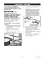
To Replace Regulator
1. Release all air pressure from air
tank. See "To Drain Tank" in the
Maintenance section.
2,
3.
Unplug unit.
Using an adjustable wrench or
specified wrench remove the
gauges (7/16" wrench), quick
connect (13/16" wrench), and
safety valve (9/16" wrench) from
the regulator manifold.
Remove the hose by removing
the hose clamp. NOTE: The hose
clamp is not reusable. You must
purchase a new hose clamp, see
the Parts List Manual or purchase
a standard hose clamp at a local
hardware store.
5,
Hose Clamp
Using an adjustable wrench or
5/8" wrench remove the regulator
manifold.
6. Apply pipe sealant to new
regulator manifold and assemble,
tighten with wrench.
7. Reapply pipe sealant to gauges,
quick connect, and safety valve.
8. Reassemble all components in
reverse order of removal. Make
sure to orient gauges to read
correctly and use wrenches to
tighten all components.
Before you store the air compressor,
make sure you do the following:
1. Review the Maintenance section
on the preceding pages and
perform scheduled maintenance
as necessary.
2. Set the On/Auto/Off lever to
"OFF" and unplug unit.
3. Turn the regulator
counterclockwise and set the
outlet pressure to zero.
4. Remove the air tool or accessory.
5. Pull ring on safety valve allowing
air to bleed from the tank until
tank pressure is approximately
20 psi. Release safety valve ring.
6. Drain water from air tank by
opening drain valve on bottom of
tank.
_Risk of Bursting.
Water will
condense in the air tank. if not
drained, water will corrode and
weaken the air tank causing a risk
of air tank rupture.
7. After the water has been drained,
close the drain or drain valve.
1000001267 18-ENG

NOTE: If drain valve is plugged,
release all air pressure. The valve
can then be removed, cleaned, then
reinstalled.
8. Protect the electrical cord and 9.
air hose from damage (such
as being stepped on or run
over). Wind them loosely around
the compressor handle. (If so
equipped)
Store the air compressor in a
clean and dry location.
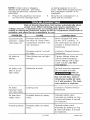
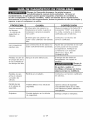
Risk of Unsafe Operation. Unit cycles automatically when
power is on. When servicing, you may be exposed to
voltage sources, compressed air, or moving parts. Before servicing unit
unplug or disconnect electrical supply to the air compressor, bleed tank of
pressure, and allow the air compressor to cool.
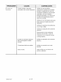
PROBLEM CORRECTION
Excessive tank
pressure - safety
valve pops off.
Air leaks at
fittings.
Air leaks in air
tank or at air
tank welds.
Air leaks
between head
and valve plate.
Air leak from
safety valve.
Knocking Noise.
CAUSE
Pressure switch does
not shut off motor when
compressor reaches "cut-
out" pressure.
Pressure switch "cut-out"
too high.
Tube fittings are not tight
enough.
Defective air tank.
Leaking seal.
Possible defect in safety
valve.
Possible defect in safety
valve.
Move On/Auto/Off lever
to the "OFF" position, if
the outfit does not shut off
contact a Trained Service
Technician.
Contact a Trained Service
Technician.
Tighten fittings where air
can be heard escaping.
Check fittings with soapy
water solution. Do Not
Overtighten.
Air tank must be replaced.
Do not repair the leak.
_Risk of
Bursting.
Do not drill into, weld or
otherwise modify air tank
or it will weaken. The tank
can rupture or explode.
Contact a Trained Service
Technician.
Operate safety valve
manually by pulling on ring.
If valve still leaks, it should
be replaced.
Operate safety valve
manually by pulling on ring.
If valve still leaks, it should
be replaced.
19-ENG 1000001267

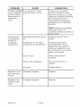
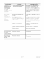
PROBLEM
Pressure reading
on the regulated
pressure gauge
drops when an
accessory is
used.
Compressor is
not supplying
enough air
to operate
accessories.
Regulator knob
has continuous
air leak.
Regulator will
not shut off air
outlet.
CAUSE
It is normal for "some"
pressure drop to occuK
Prolonged excessive use of
air.
Compressor is not large
enough for air requirement.
Hole in hose.
Check valve restricted.
Air leaks.
Damaged regulator.
Damaged regulator.
CORRECTION
If there is an excessive
amount of pressure drop
when the accessory is used,
adjust the regulator following
the instructions in the
"Description of Operation"
paragraph in the Operation
Section.
NOTE: Adjust the regulated
)ressure under flow
conditions (while accessory is
bein used.
Decrease amount of air
usage.
Check the accessory
air requirement. If it is
higher than the SCFM or
)ressure supplied by your
air compressor, you need a
larger compressor.
Check and replace if
required.
Remove and clean, or
replace.
Tighten fittings.
Replace.
Replace.
1000001267 20-ENG
Page is loading ...
Page is loading ...
Page is loading ...
Page is loading ...
Page is loading ...
Page is loading ...
Page is loading ...
Page is loading ...
Page is loading ...
Page is loading ...
Page is loading ...
Page is loading ...
Page is loading ...
Page is loading ...
Page is loading ...
Page is loading ...
Page is loading ...
Page is loading ...
Page is loading ...
Page is loading ...
Page is loading ...
Page is loading ...
Page is loading ...
Page is loading ...
Page is loading ...
Page is loading ...
Page is loading ...
Page is loading ...
-
 1
1
-
 2
2
-
 3
3
-
 4
4
-
 5
5
-
 6
6
-
 7
7
-
 8
8
-
 9
9
-
 10
10
-
 11
11
-
 12
12
-
 13
13
-
 14
14
-
 15
15
-
 16
16
-
 17
17
-
 18
18
-
 19
19
-
 20
20
-
 21
21
-
 22
22
-
 23
23
-
 24
24
-
 25
25
-
 26
26
-
 27
27
-
 28
28
-
 29
29
-
 30
30
-
 31
31
-
 32
32
-
 33
33
-
 34
34
-
 35
35
-
 36
36
-
 37
37
-
 38
38
-
 39
39
-
 40
40
-
 41
41
-
 42
42
-
 43
43
-
 44
44
-
 45
45
-
 46
46
-
 47
47
-
 48
48


Craftsman 919167270 Owner's manual
- Category
- Air compressors
- Type
- Owner's manual
- This manual is also suitable for
Ask a question and I''ll find the answer in the document
Finding information in a document is now easier with AI
in other languages
Related papers
-
Craftsman 919167280 Owner's manual
-
-
Craftsman 919.165570 Owner's manual
-
-
-
-
-
-
-
Other documents
-
Porter-Cable C2004 User manual
-
-
Delta ShopMaster D27930 User manual
-
-
Porter-Cable C2002-WK User manual
-
-
-
-
-