Hayter Mowers 405607x52A User manual
- Category
- Toys
- Type
- User manual

F-050743L
Instruction Book − Riding Mower Model 405607x52A
Manuel de l’utilisateur − Tondeuse autoportée modèle 405607x52A
Betriebsanleitung − Aufsitzmäher Modell 405607x52A
Istruzioni per l’uso − Trattore tagliaerba Modello 405607x52A
Gebruikshandleiding − Zitmaaier model 405607x52A
Driftsvejledning − Plænetraktor Model 405607x52A
Bruksanvisning − Rider modell 405607x52A
Användarhandbok − Trädgårdtraktor modell 405607x52A
Käyttöohjeet − Ajettava ruohonleikkuri, malli 405607x52A
Manual de instrucciones − Cortacésped autoportado Modelo 405607x52A
Manual de instruções − Cortador de Grama de Empurrar
modelo 405607x52A
F
D
I
NL
DK
N
S
SF
GB
E
P
Page is loading ...
Page is loading ...
Page is loading ...

GB
5
F-050743L
CONTENTS
INTERNATIONAL PICTORIALS 5
OWNER’S INFORMATION 6
SAFE OPERATION PRACTICES 6
ASSEMBLY 7
OPERATION 8
MAINTENANCE 9
TROUBLE SHOOTING CHART 13
MURRAY, INC.
TWO YEAR LIMITED WARRANTY
Murray, Inc. warrants to the original purchaser
that this unit shall be free from defects in
material and workmanship under normal use
and service for a period of Two (2) Years from
the date of purchase; however, this warranty
does not cover engines, accessories (such as
snow blowers, snow blades, grass baggers and
ploughs), transmissions, batteries and Normal
Wear Parts (except as noted below) or
transaxles as the companies that manufacture
these items furnish their own warranties and
provide service through their authorized field
service facilities. For additional information, see
the warranties covering these particular parts. If
you are uncertain whether your unit contains or
is equipped with one or more of these parts,
consult your dealer prior to purchase. Subject to
the terms and conditions noted in this Limited
Warranty, we shall, at our option, repair or
replace at no cost to the original purchaser any
part covered by this Limited Warranty during the
applicable warranty period.
In the event the battery proves defective within
ninety (90) days from the date of purchase, we
will replace it without charge. If the battery
proves defective after (90) days but within one
hundred twenty (120) days from the date of
purchase, we will replace it for a charge of one
half (1/2) of the retail price of the battery in effect
at the time of return.
Normal Wear Parts are defined as belts, blades,
blade adapters, pneumatic tyres, headlights and
seat covers. These parts are warranted to be
free from defects in material and workmanship
as delivered with the product. Any claim for
repair or replacement of Normal Wear Parts
must be made within thirty (30) days of the date
of purchase. No claims involving damage
caused from material use, abuse or misuse will
be honoured.
This Murray, Inc. Two (2) Year Limited
Warranty is your exclusive remedy; however,
this warranty is void or does not apply to any
unit that has been tampered with, altered,
misused, abused or used for rental or other
commercial and/or professional
(non-homeowner) uses. Your warranty does not
cover minor mechanical adjustments which are
not due to any defect in material or
workmanship. For assistance in making such
adjustments, consult your Instruction Book.
To make a claim under this Murray, Inc. Two (2)
Year Limited Warranty, return the unit (or if
authorized in advance, the defective part) along
with your proof of purchase to an Authorized
Service Centre near you. To locate the nearest
Authorized Service Centre, call the Central Parts
Distributor for your area shown in the list
provided with your unit or check the Yellow Page
listings in your local telephone directory. If you
return the entire unit, we will repair the unit. If we
authorize the return of the defective part only, we
will either replace or repair the part. In the case
of a defect in a transmission or differential (as
distinguished from a transaxle), the entire
transmission or differential must be returned
since they do not include user serviceable parts.
This Murray, Inc. Two (2) Year Limited
Warranty gives you specific legal rights, and
you may also have other rights which vary from
state to state. This Limited Warranty is given
in lieu of all other expressed and implied
warranties including the implied warranty of
merchantability and warranty of fitness for a
particular purpose. If you need additional
information on this written warranty or
assistance in obtaining service, write:
HAYTER LIMITED,
Service Department,
Spellbrook,
Bishop’s Stortford,
Hertfordshire. CM23 4BU.
MURRAY, INC.
International Sales
P.O. Box 268
Brentwood, Tennessee USA 37024
1-800-251-8007
Fax (615) 373-6633
INTERNATIONAL PICTORIALS
IMPORTANT: The following pictorials are lo-
cated on your unit or on literature supplied
with the product. Before you operate the
unit, learn and understand the purpose for
each pictorial.
NOTE: Illustrations and pictorials begin
on page 2.
Safety Warning Pictorials (Figure 23)
1 WARNING
2 IMPORTANT: Read Owner’s Manual
Before Operating This Machine.
3 WARNING: Thrown Objects. Keep
Bystanders Away. Read User Instructions
Before Operating This Machine.
4 WARNING: Do Not Use This Machine On
Slopes Greater Than 10 Degrees.
5 DANGER: Keep People, Especially
Children, Away From Unit.
6 DANGER: No Step.
7 DANGER: Keep Feet And Hands Away
From Rotating Blade.
8 Declared airborne sound power level of 100
dB(A) is in accordance with Directive
2000/14/EC.
9 DANGER: Disconnect Spark Plug Wire
Before Servicing Unit.
10 WARNING: Hot Surface.
11 WARNING: Use Caution When Connecting
Or Disconnecting Accessories.
12 WARNING: Crushed Fingers.
13 IMPORTANT: Follow Instructions In
Owner’s Manual To Level The Deck.
14 WARNING: Stay Clear Of Mower Blade As
Long As Engine Is Running.
Control And Operating Pictorials
(Figure 24)
1 Engine Start
2 Lights
3 Engine Run
4 Engine Stop
5 Engine Run
6 Brake
7 Parking Brake
8 Clutch
9 Slow
10 Fast
11 Choke
12 Oil
13 Blade Rotation Control
14 Raise
15 Fuel
Declared vibration emission values in accordance with Directive 98/37/EC.
Vibration Emission according to BS EN 1032: Seat < 0,5 m/s
2
,
Right Running Board 2,35 m/s
2
, Left Running Board 4,34 m/s
2
Vibration Emission according to BS EN 1033: Steering Wheel 6,28 m/s
2
Values determined with operator in operating position when the machine was
operated stationary on a concrete surface at 2850 min-1.
MODEL NO.: 405607x52A
SERIAL NO.:
2850 min-1
172 kg
SKU No.:
Assembled in Lawrenceburg, TN 38464, U.S.A.
YYYY MM DD:
Declared airborne sound power level of 100 dB(A) is in accordance with Directive
2000/14/EC.
Sound Pressure Level at operator position 82 dB.
Values determined at ear according to the specifications of EN 836/A2:2001.

GB
6
F-050743L
OWNER’S INFORMATION
Know your product: If you understand the unit
and how the unit operates, you will get the best
performance. As you read this manual, compare
the illustrations to the unit. Learn the location
and the function of the controls. To help prevent
an accident, follow the operating instructions
and the safety rules. Keep this manual for future
reference.
WARNING: Look for this symbol to indicate
important safety precautions. This symbol
indicates: “Attention! Become Alert! Your
Safety Is At Risk.”
Responsibility Of The Owner
WARNING: This cutting machine is
capable of amputating hands and
feet and throwing objects. Failure
to observe the following safety instructions
could result in serious injury or death to
the operator or bystanders.
The responsibility of the owner is to
follow the instructions below.
SAFE OPERATION PRACTICES
For Ride-On (Riding)
Rotary Mower Machines
Training
1. Read the instructions carefully. Be familiar
with the controls and the proper use of the
equipment.
2. Never allow children or people unfamiliar
with these instructions to use the mower.
Local regulations may restrict the age of
the operator.
3. Never mow while people, especially
children, or pets are nearby.
4. Keep in mind that the operator or user is
responsible for accidents or hazards occur-
ring to other people or their property.
5. Do not carry passengers.
6. All drivers should seek and obtain pro-
fessional and practical instruction. Such
instruction should emphasize:
a. the need for care and concentration
when working with ride-on machines;
b. control of a ride-on machine sliding
on a slope will not be regained by the
application of the brake. The main
reasons for loss of control are:
insufficient wheel grip;
being driven too fast;
inadequate braking
the type of machine is unsuitable
for its task;
lack of awareness of the effect of
ground conditions, especially
slopes;
incorrect hitching and load dis-
tribution.
Preparation
1. While mowing, always wear substantial
footwear and long trousers. Do not operate
the equipment when barefoot or wearing
open sandals.
2. Thoroughly inspect the area where the
equipment is to be used and remove all ob-
jects which may be thrown by the machine.
3. WARNING - Petrol is highly flammable.
a. Store fuel in containers specifically de-
signed for this purpose.
b. Refuel outdoors only and do not
smoke while refuelling.
c. Add fuel before starting the engine.
Never remove the cap of the fuel tank
or add petrol while the engine is run-
ning or when the engine is hot.
d. If petrol is spilled, do not attempt to
start the engine but move the machine
away from the area of spillage and
avoid creating any source of ignition
until petrol vapours have dissipated.
e. Replace all fuel tanks and container
caps securely.
4. Replace faulty silencers.
5. Before using, always visually inspect to see
that the blades, blade bolts and cutter as-
sembly are not worn or damaged. Replace
worn or damaged blades and bolts in sets
to preserve balance.
6. On multi-blade machines, take care as ro-
tating one blade can cause other blades to
rotate.
Operation
1. Do not operate the engine in a confined
space where dangerous carbon monoxide
fumes can collect.
2. Mow only in daylight or in good artificial
light.
3. Before attempting to start the engine, dis-
engage all blade attachment clutches and
shift into neutral.
4. Do not use on slopes of more than 10 de-
grees.
5. Remember there is no such thing as a
“safe” slope. Travel on grass slopes re-
quires particular care. To guard against
overturning:
a. do not stop or start suddenly when
going up or downhill;
b. engage clutch slowly, always keep
machine in gear, especially when tra-
velling downhill;
c. machine speeds should be kept low
on slopes and during tight turns;
d. stay alert for humps and hollows and
other hidden hazards;
e. never mow across the face of the
slope, unless the mower is designed
for this purpose.
6. Use care when pulling loads or using heavy
equipment.
a. Use only approved drawbar hitch
points.
b. Limit loads to those you can safely
control.
c. Do not turn sharply. Use care when
reversing.
d. Use counterweight(s) or wheel
weights when suggested in the In-
struction Book.
7. Watch out for traffic when crossing or near
roadways.
8. Stop the blades rotating before crossing
surfaces other than grass.
9. When using any attachments, never direct
discharge of material toward bystanders
nor allow anyone near the machine while in
operation.
10. Never operate the mower with defective
guards or shields, or without safety protec-
tive devices in place.
11. Do not change the engine governor set-
tings or overspeed the engine. Operating
an engine at excessive speed may in-
crease the hazard of personal injury.
12. Before leaving the operator’s position
a. disengage the power take-off and
lower the attachments;
b. change into neutral and set the park-
ing brake;
c. stop the engine and remove the key.
13. Disengage drive to attachments, stop the
engine, and disconnect the spark plug
wire(s) or remove the ignition key
a. before cleaning blockages or unclog-
ging chute;
b. before checking, cleaning or working
on the mower;
c. after striking a foreign object. Inspect
the mower for damage and make re-
pairs before restarting and operating
the equipment;
d. if the machine starts to vibrate abnor-
mally (check immediately).
14. Disengage drive to attachments when
transporting or not in use.
15. Stop the engine and disengage drive to at-
tachment
a. before refuelling;
b. before removing the grass catcher;
c. before making height adjustment un-
less adjustment can be made from the
operator’s position.
16. Reduce the throttle setting during engine
run-out and, if the engine is provided with a
shut-of f valve, turn the fuel off at the con-
clusion of mowing.
17. Before and when backing, look behind and
down for small children.
18. Use extra care when approaching blind
corners, shrubs, trees or other objects that
may obscure vision.
Maintenance and Storage
1. On multi-blade machines, take care as ro-
tating one blade can cause other blades to
rotate.
2. When machine is to be parked, stored or
left unattended, lower the cutting means
unless a positive mechanical lock is used.
3. Keep all nuts, bolts, and screws tight to be
sure the equipment is in safe working
condition.
4. Never store the equipment with petrol in the
tank inside a building where fumes may
reach an open flame or spark.
5. Allow the engine to cool before storing in
any enclosure.
6. To reduce the fire hazard, keep the engine,
silencer, battery compartment and petrol
storage area free of grass, leaves, or ex-
cessive grease.
7. Check the grass catcher frequently for
wear or deterioration.
8. Replace worn or damaged parts for safety.
9. If the fuel tank has to be drained, this
should be done outdoors.

GB
7
F-050743L
ASSEMBLY
All fasteners are in the parts bag. Do not discard
any parts or material until the unit is assembled.
WARNING: Before doing any as-
sembly or maintenance to the
mower, remove the wire from the
spark plug.
NOTE: In this instruction book, left and right
describe the location of a part with the oper-
ator on the seat.
NOTE: Illustrations and pictorials begin on
page 2.
NOTE: To assemble the following loose
parts, use the fasteners shown at full size in
Figure 25.
How To Install The Front Wheels
(Figure 1)
Use a knife and cut the four sides of the con-
tainer. Install the front wheels (1) in the con-
tainer.
NOTE: Use a piece of wood about 4 feet (1.25
meters) long to raise the front of the tractor.
If a piece of wood cannot be found, get
another person to help lift the tractor. Be
careful, do not let the tractor fall.
1. Raise the front of the tractor. Set a support
(block of wood) under the tractor.
2. Make sure the valve stem (2) is to the out-
side of the tractor. Slide the front wheel (1)
on the spindle (3).
3. Fasten each front wheel (1) with washer (4)
and cotter pin (5). Bend the ends of the
cotter pin (5) appart to keep the front wheel
(1) on the spindle (3).
4. After the front wheels (1) are installed, lift
the tractor from the support. Roll the tractor
off of the container.
5. If your tractor has hub caps (6), install the
hub caps (6). Make sure the washers (4)
hold the hub caps (6) in place.
How To Install The Seat (Figure 2)
1. Carefully remove the plastic bag from the
seat (1).
2. Align the holes in the seat hinge (2) to the
holes in the seat (1). Fasten the seat (1) to
the seat hinge (2) with the fasteners (4) and
(5).
3. Check the operating position of the seat (1).
If the seat (1) needs to be adjusted, loosen
the two wing bolts (5). Slide the seat (1) for-
ward or backward along the seat adjusting
holes (3). Tighten the wing bolts (5).
How To Assemble The Steering Wheel
(Figure 3)
1. Make sure the front wheels point forward.
2. Slide the cover (3) over the steering post
(2). Make sure the collar of the cover (3) is
on top.
3. Slide the steering wheel (1) onto the steer-
ing post (2).
4. Attach the steering wheel (1) to the steer-
ing post (2) with screw (4) and washer (6).
5. Some models have an optional insert (7) in
the parts bag. Attach the insert (7) to the
centre of the steering wheel (1).
Maintenance Free Battery (Figure 4)
IMPORTANT: Before you attach the battery
cables to the battery, check the battery date.
The battery date tells if the battery must be
charged.
1. Check the top and the side of the battery (1)
for the location of the battery date.
2. If the battery (1) is put into service before
the , the battery cables can be attached with-
out charging the battery (1). See “How To
Install The Battery Cables”.
3. If the battery (1) is put into service after the ,
the battery (1) must be charged. See “How
To Charge The Maintenance Free Battery”.
How To Charge The Battery (Figure 4)
WARNING: When you charge the
battery, do not smoke. Keep the bat-
tery away from any sparks. The
fumes from the battery acid can cause an
explosion.
1. Remove the battery (1) and battery tray (3).
2. Remove the protective cap from the battery
terminal.
3. Use a 12 volt battery charger to charge the
battery (1). Charge at a rate of 6 amperes
for one hour. If you do not have a battery
charger, have an authorized service centre
charge the battery.
4. Install the battery (1) and battery tray (3).
Make sure the positive (+) terminal (4) is on
the left side.
How To Install The Battery Cables
(Figure 4)
WARNING: To prevent sparks, faste
n
the red cable to the positive (+) ter-
minal before you connect the black
cable.
1. Remove the protective cap from the battery
terminal.
2. Slide the terminal cover (2) onto the red
cable (5). Fasten the red cable (5) to the
positive (+) terminal (4) with the fasteners
(6) and (7).
3. Fasten the black cable 8 to the negative (-)
terminal with the fasteners (6) and (7).
Check The Tyres
Check the air pressure in the tyres. Tyres with
too much air pressure will cause the unit to ride
rough. Also, the wrong air pressure will keep the
mower housing from cutting level. The correct
air pressure is: Front Tyres 0,97 BAR (14 PSI),
Rear Tyres 0,69 BAR (10 PSI). The tyres were
over inflated for shipment.
Check The Level Of The Mower
Housing
Make sure the level of cut is still correct. After
you mow a short distance, look at the area that
was cut. If the mower housing does not cut level,
see the instructions on “How To Level The
Mower Housing” in the Maintenance section of
this instruction book.
How To Prepare The Engine
NOTE: The engine was shipped from the fac-
tory filled with oil. Check the level of the oil.
Add oil as needed.
See the engine manufacturer’s instructions for
the type of petrol and oil to use. Before you use
the unit, read the information on safety, oper-
ation, maintenance, and storage.
WARNING: Follow the engine manu-
facturer’s instructions for the type o
f
petrol and oil to use. Always use a
safety petrol container. Do not smoke when
adding petrol to the engine. When inside an
enclosure, do not fill with petrol. Before you
add petrol, stop the engine. Let the engine
cool for several minutes.
Important! Before You Start Mowing
Check the engine oil.
Fill the fuel tank with petrol.
Check the air pressure of the tyres.
Check the level of the mower hous-
ing.
Attach the battery cables.

GB
8
F-050743L
OPERATION
NOTE: Illustrations and pictorials begin on
page 2.
Location Of Controls (Figure 5)
Blade Rotation Control (1): Use the blade rota-
tion control to start and stop the rotation of the
blade.
Brake Pedal (2): Use the brake pedal to quickly
stop.
Headlight Switch (3): The headlight switch is
the first part of the ignition switch. To use the
lights with the engine running, turn the key to the
position for the lights.
Ignition Switch (3): Use the ignition switch to
start and stop the engine.
Speed Control Pedal (4): Use the speed con-
trol pedal to change the speed and the direction
of the unit.
Lift Lever (5): Use the lift lever to change the
height of cut.
Parking Brake Lever (6): Use the parking brake
lever to engage the brake when you leave the
unit.
Throttle Control Lever (7): Use the throttle
control lever to increase or decrease the speed
of the engine.
Automatic Drive disconnect (8): use the auto-
matic drive disconnect, located under the seat,
to disengage the transmission.
Attachments
This unit can use many different attachments.
This unit can pull attachments like a lawn
sweeper, a lawn aerator, or a hopper spreader.
This unit can not use attachments that engage
the ground like a plough, a disk harrow, or a
cultivator.
For trailer and pull-behind attachments, the
maximum weight is 113 kg (250 lbs.).
How To Use The Throttle Control
(Figure 5)
Use the throttle control (7) to increase or de-
crease the speed of the engine.
1. The FAST position is marked with a detent.
For normal operation and when using a
grass bagger, move the throttle control to the
FAST position. For maximum charging of the
battery and for a cooler running engine, oper-
ate the engine in the FAST position.
2. The engine governor is set at the factory for
maximum performance. Do not adjust the
governor to increase the speed of the en-
gine.
How To Use The Blade Rotation Control
(Figure 5)
Use the blade rotation control (1) to engage
the blade(s).
1. Before you start the engine, make sure the
blade rotation control (1) is in the DISEN-
GAGE position.
2. Move the blade rotation control (1) to the
ENGAGE position to rotate the blade(s).
NOTE: If the engine stops when you en-
gage the blade(s), the seat switch is not
activated. Make sure you sit in the middle
of the seat.
3. Move the blade rotation control (1) to the
DISENGAGE position to stop the blade(s).
Before you leave the operator’s position,
make sure the blade(s) has stopped rotating.
4. Before you ride the unit across a sidewalk or
a road, move the blade rotation control (1)
to the DISENGAGE position.
WARNING: Always keep your
hands and feet away from the
blade, deflector opening, and the
mower housing when the engine runs.
How To Use The Speed Control Pedal
(Figure 5)
The drive system uses a Hydrostatic Automatic
Drive transmission. The Hydrostatic trans-
mission is very easy to operate. This type of
drive system does not require a shift lever or a
clutch pedal.
The speed and direction of travel is controlled by
a single speed control pedal (4) operated with
your right foot. Do not use the left brake pedal in
normal operation. Only use the left brake pedal
to quickly stop in an emergency.
How To Drive Forward
1. (Figure 20) The automatic drive discon-
nect (1) must be in the DRIVE position (2).
2. Slowly release your left foot from the brake
pedal.
3. Move the throttle control to the FAST posi-
tion.
4. (Figure 19) Slowly push the speed control
pedal (1) forward (4) to the desired speed.
5. To increase forward speed, slowly move the
speed control pedal (1) forward. To reduce
forward speed, slowly release the speed
control pedal (1) until the unit slows to the
desired speed.
How To Drive In Reverse
1. Look to the rear.
2. Slowly push the speed control pedal (1) to
the REVERSE position (2).
How To Change Directions
CAUTION: To change directions, do not use
the left brake pedal. Use only the speed con-
trol pedal.
1. Slowly remove your foot from the speed
control pedal (1). The speed control pedal
(1) will automatically return to the NEUTRAL
position (3).
2. When the unit stops, slowly move the speed
control pedal (1) to the desired direction.
How To Disconnect The Transmission
(Figure 20)
To push the unit, use the automatic drive dis-
connect (1) to release the transmission. The
automatic drive disconnect (1) is under the
seat.
1. The engine must be off.
2. Raise the seat. The automatic drive dis-
connect (1) is under the seat.
3. Move and latch the automatic drive discon-
nect (1) in the PUSH position (3). The
transmission is now released and the unit
can be pushed.
NOTE: In cold weather, the heavy viscos-
ity oil in the transmission will make the
unit difficult to push.
4. To engage the transmission, unlatch the au-
tomatic drive disconnect (1). The trans-
mission is now connected and ready to
operate.
How To Use The Parking Brake
(Figure 5)
1. Completely push the brake pedal (2) for-
ward.
2. Lift the parking brake lever (6).
3. Remove your foot from the brake pedal (2)
and then release the parking brake lever
(6). Make sure the parking brake will hold the
unit.
4. To release the parking brake (6), completely
push the brake pedal (2) forward. The park-
ing brake will automatically release.
WARNING: Before you leave the
operator’s position, set the parking
brake. Move the blade rotation con-
trol to the DISENGAGE position. Stop the
engine and remove the ignition key.
How To Change The Cutting Height
(Figure 5)
To change the cutting height, raise or lower the
lift lever (5) as follows.
1. Move the lift lever (5) forward to lower the
mower housing and back to raise the mower
housing.
2. When you ride on a sidewalk or road, move
the lift lever (5) to the highest position and
move the blade rotation control to the DIS-
ENGAGE position.
How To Stop The Unit (Figure 5)
1. Slowly remove your foot from the speed
control pedal (4). The speed control pedal
(1) will automatically return to the NEUTRAL
position and the unit will stop.
2. Move the blade rotation control (1) to the
DISENGAGE position.
3. Set the parking brake (6).
WARNING: Make sure the parking
brake will hold the unit.
4. Move the throttle control (7) to the SLOW
position.
5. To stop the engine, turn the ignition key (3)
to the OFF position. Remove the key.
How To Transport The Unit
To transport the unit, follow the steps below.
1. Move the blade rotation control to the DIS-
ENGAGE position.
2. Raise the lift lever to the highest position.
3. Move the throttle control to a position be-
tween SLOW and FAST.

GB
9
F-050743L
4. Slowly push the speed control pedal forward
to the desired speed.
How To Operate With The Mower
Housing
IMPORTANT: When you operate with the
mower housing, always operate with the
throttle control in the FAST position.
1. Start the engine.
2. Move the lift lever to a height of cut position.
In high or thick grass, cut the grass in the
highest position first and then lower the
mower housing to a lower position.
3. Move the throttle control to the SLOW posi-
tion.
4. Slowly move the blade rotation control to the
ENGAGE position.
5. Move the throttle control to the FAST posi-
tion.
6. Slowly push the speed control pedal to the
desired speed.
NOTE: When you mow in heavy grass or
mow with a bagger, use a slow forward
speed.
7. Make sure the level of cut is still correct.
After you mow a short distance, look at the
area that was cut. If the mower housing does
not cut level, see the instructions on “How To
Level The Mower Housing” in the Mainten-
ance section.
WARNING: For better control of the
unit, select a safe speed.
How To Operate On Hills
WARNING: Do not ride up or down
slopes that are too steep to back
straight up. Never ride the unit
across a slope.
1. Control the speed only with the speed control
pedal. Do not use the brake pedal on a hill.
2. To help prevent an accident, slowly move the
speed control pedal. Avoid sudden turns or
changes in speed.
3. To reduce forward speed when going down a
hill, slowly release the speed control pedal
until the unit slows to the desired speed.
How To Stop On a Hill
1. Avoid stopping on a hill. If you must quickly
stop in an emergency, remove your right foot
from the speed control pedal and quickly de-
press the left brake pedal.
2. Set the parking brake.
3. Before you dismount from the seat, move the
throttle control to the SLOW position, move
the blade rotation control to the DISEN-
GAGED position, turn off the engine and set
the parking brake.
How To Start Operation On A Hill
1. Start the engine
2. Move the blade rotation control to the EN-
GAGED position.
3. Move the throttle control to the FAST posi-
tion.
4. Depress the brake pedal and release the
parking brake. As you release the parking
brake, push the speed control pedal to the
desired speed.
Slowly push the speed control
pedal as you release the parking
brake. The parking brake must be
disengaged before the speed control pedal
is able to engage the transmission.
Before Starting The Engine
Check the oil
NOTE: The engine was shipped from the fac-
tory filled with oil. Check the level of the oil.
Add oil as needed. See the engine manufac-
turer’s instructions for the type of petrol and
oil to use.
1. Make sure the unit is level.
NOTE: Do not check the level of the oil
while the engine runs.
2. Check the oil. Follow the procedure in the
engine manufacturer’s instructions.
3. If necessary, add oil until the oil reaches the
FULL mark on the dipstick. The quantity of oil
needed from ADD to FULL is shown on the
dipstick. Do not add too much oil.
Add Petrol
WARNING: Always use a safety
petrol container. Do not smoke
when adding petrol to the fuel tank.
Do not add petrol when you are inside an
enclosure. Before you add petrol, stop the
engine and let the engine cool for several
minutes.
(Figure 6) Fill the fuel tank (1) to the FULL (2)
position with regular unleaded petrol. Do not use
premium unleaded petrol. Make sure the petrol
is fresh and clean. Leaded petrol will increase
deposits and shorten the life of the valves.
How To Start The Engine
WARNING: The electrical system
has an operator presence system
that includes a sensor switch for
the seat. These components tell the
electrical system if the operator is sitting
on the seat. This system will stop the
engine when the operator leaves the seat.
For your protection, always make sure this
system operates correctly.
NOTE: The engine will not start unless you
depress the clutch/brake pedal and move the
blade rotation control to the DISENGAGE
position.
1. Push the brake pedal completely forward.
Keep your foot on the pedal.
2. Make sure the blade rotation control is in the
DISENGAGE position.
3. Move the throttle control completely forward
to the CHOKE or FAST position. Some mo-
dels have a separate choke knob. Pull the
choke knob to the full CHOKE position.
4. Turn the ignition key to the START position.
NOTE: If the engine does not start after
four or five tries, move the throttle control
to the FAST position. Again try to start the
engine. If the engine will not start, see the
TROUBLE SHOOTING CHART.
5. Slowly move the throttle control to the SLOW
position.
6. To start a hot engine, move the throttle con-
trol to a position between FAST and SLOW.
Mowing And Bagging Tips
1. For a lawn to look better, check the cutting
level of the mower housing. See “How To
Level The Mower Housing” in the Mainten-
ance section.
2. For the mower housing to cut level, make
sure the tyres have the correct amount of air
pressure.
3. Every time you use the unit, check the blade.
If the blade is bent or damaged, immediately
replace the blade. Also, make sure the nut
for the blade is tight.
4. Keep the blade(s) sharpened. Worn blades
will cause the ends of the grass to turn
brown.
5. Do not cut or bag grass that is wet. Wet
grass will not discharge correctly. Let the
grass dry before cutting.
6. Use the left side of the mower housing to trim
near an object.
7. Discharge the cut grass onto the mowed
area. The result is a more even discharge of
cut grass.
8. When you mow large areas, start by turning
to the right so that the cut grass will dis-
charge away from shrubs, fences, driveways,
etc. After one or two rounds, mow in the op-
posite direction making left turns until fin-
ished.
9. If the grass is very high, cut two times to de-
crease the load on the engine. First cut with
the mower housing in the highest position
and then lower the mower housing for the
second cut.
10.For better engine performance and an even
discharge of the cut grass, always operate
the engine with the throttle in FAST position.
11. When you use a bagger, operate the engine
with the throttle in FAST position and the
speed control pedal pushed 1/3 to 1/2 for-
ward..
12.After each use, clean the bottom and top of
the mower housing for better performance.
Also, a clean mower housing will help pre-
vent a fire.
MAINTENANCE
NOTE: Illustrations and pictorials begin on
page 2.
General Recommendations
1. The owner’s responsibility is to maintain this
product. This will extend the life of the prod-
uct and is also necessary to maintain war-
ranty coverage.
2. Check the spark plug, drive brake, lubricate
the unit, and clean the air filter once a year.
3. Check the fasteners. Make sure all fasteners
are tight.

GB
10
F-050743L
4. Follow the Maintenance section to keep the
unit in good operating condition.
WARNING: Before you make an in-
spection, adjustment, or repair to
the unit, disconnect the wire to the
spark plug. Remove the wire from the
spark plug to prevent the engine from
starting by accident.
NOTE: Torque is measured in foot pounds
(metric Nm). This measurement describes
how tight a nut or bolt must be. The torque is
measured with a torque wrench.
Inspect Blade (Figure 7)
WARNING: Before you inspect or
remove the blade, disconnect the
wire to the spark plug. If the blade
hits an object, stop the engine. Check the
unit for damage. The blade has sharp
edges. When you hold the blade, use
gloves or cloth material to protect your
hands.
If you keep the blade (1) sharp and inspect the
blade for damage, the blade will cut better and
be more safe to operate. Frequently check the
blade for excessive wear, cracks, or other dam-
age. Frequently check the nut (3) that holds the
blade (1). Keep the nut (3) tight. If the blade hits
an object, stop the engine. Disconnect the wire
to the spark plug. See if the blade is bent or
damaged. Check the blade adapter (5) for dam-
age. Before you operate the unit, replace dam-
aged parts with original equipment parts. See
the authorized service centre in your area. Every
three years, have an authorized service person
inspect the blade or replace the old blade with
an original equipment part.
How To Remove And Install The Blade
(Figure 7)
1. Remove the mower housing. See the instruc-
tions on “How To Remove The Mower Hous-
ing”.
2. Use a piece of wood to keep the blade from
rotating.
3. Remove the nut (3) that holds the blade (1).
4. Check the blade (1) and the blade adapter
(5) according to the instructions for “Inspect
Blade”. Replace a badly worn or damaged
blade with an original equipment blade. See
an authorized service centre in your area.
5. Clean the top and bottom of the mower hous-
ing. Remove all the grass and debris.
6. Mount the blade (1) and blade adapter (5)
on the mandrel (6).
7. Mount the blade (1) so that the hi-lift edges
(7) are up. If the blade is upside down, the
blade will not cut correctly and can cause an
accident.
8. Fasten the blade (1) with the original
washers and nut (3). Make sure the outside
rim of the Belleville washer (2) is against
the blade (1).
WARNING: Always keep the nut (3)
tight that holds the blade (1). A
loose nut or blade can cause an
accident.
9. Tighten the nut (3) that holds the blade (1) to
a torque of 30 foot pounds (41,5 Nm).
10.Install the mower housing. See “How To Re-
move The Mower Housing”.
How To Adjust The Blade Rotation
Control
WARNING: To prevent an injury, the
blade rotation control must operate
correctly.
In normal usage, the blade rotation control will
not require an adjustment. However, if the cut-
ting performance decreases or the quality of cut
is poor, make the following changes.
1. When you mow, make sure the throttle con-
trol in in the FAST position.
2. (Figure 8) Move the blade rotation control to
the DISENGAGE position (1).
3. Stop the engine. Disconnect the wire from
the spark plug.
4. Check the blade(s). Keep a sharp edge on
the blade(s). A blade that is not sharp will
cause the tips of the grass to become brown.
5. (Figure 9) Disconnect the blade drive
spring (2) from the blade control rod (1).
Move the blade drive spring (2) to the
middle hole (4). This will increase the ten-
sion on the mower drive belt.
6. Attach the wire to the spark plug. Mow for a
short distance and again check the quality of
cut. If necessary, move the blade drive
spring (2) to the bottom hole (5)
7. Again check the quality of cut. If the quality of
cut has not improved, replace the mower
drive belt. See “How To Replace The Mower
Drive Belt”. If the replacing the belt does not
correct the problem, take the unit to an auth-
orized service centre.
8. Move the blade rotation control to the DIS-
ENGAGE position. Stop the engine.
9. (Figure 10) Check the operation of the blade
brake. Rotate the pulleys with your hand.
Make sure the brake pads (1) are pressed
tightly against the pulleys
WARNING: If the brake pads (1) do
not press tightly against the
pulleys, take the unit to an author-
ized service centre.
10.(Figure 8) Move the blade rotation control to
the ENGAGE position (2).
11. (Figure 10) Check the pads for the blade
brake (7). If the pads are excessively worn
or damaged, replace the brake pad assem-
blies. Correct replacement parts and assist-
ance are available from an authorized
service centre.
12.Attach the wire to the spark plug. Mow for a
short distance and again check the operation
of the blade rotation control.
13.When you move the blade rotation control to
the DISENGAGE position, all movement will
stop within five seconds. If there is move-
ment of the belt or the blades continue to ro-
tate, engage and disengage the blade
rotation control five times to remove any ex-
cess rubber from a new mower drive belt. If
you need assistance, take the unit to an
authorized service centre.
14.(Figure 9) If you replace the mower drive
belt, move the blade drive spring (2) to the
top hole (3).
How To Check And Adjust The Motion
Drive Belt (Figure 18 and Figure 21)
If the motion drive belt is loose, the belt will slip
when; going up a hill, pulling a heavy load, or the
unit will not move forward.
IMPORTANT: Always operate with the engine
speed in the FAST position. If the engine
speed is in a slow or moderate position, the
engine and transmission can become too hot
and cause problems that are similar to a
loose motion drive belt.
WARNING: Before you make an in-
spection, adjustment, or repair to
the unit, disconnect the wire to the
spark plug. Remove the wire from the
spark plug to prevent the engine from
starting by accident.
1. (Figure 21) Check the routing of the motion
drive belt (6). Make sure the motion drive
belt (6) is installed correctly and is inside all
the belt guides (7).
2. (Figure 18) Disconnect the clutch link (1)
from the idler arm (2).
3. (Figure 21) Align the hole in the brake lever
(3) with the hole in the frame. Hold the brake
lever (3) in place with a 1/4 inch (6 mm) pin
or bolt (4).
4. (Figure 18) Rotate the clutch link (1) until
the mounting hole (5) in the clutch link (1)
is aligned with the mounting hole (5) in the
idler arm (2).
5. Connect the clutch link (1) to the idler arm
(2).
6. (Figure 21) Remove the 1/4 inch (6 mm)
pin or bolt (4).
7. If the belt still slips after the belt has been
adjusted, then the motion drive belt is worn
or damaged and must be replaced. See
“How To Replace The Motion Drive Belt”.
How To Check And Adjust The Drive
Brake (Figure 12 and 20)
(Figure 20) Set the parking brake. Move the au-
tomatic drive disconnect (1) to the PUSH
position (3). Push the unit. If the rear wheels
rotate, adjust or replace the brake pads.
Adjust the drive brake (4) as follows:
1. (Figure 12) The location of the drive brake
(4) is on the right side of the gearbox (5).
2. (Figure 20) Make sure the parking brake is
set and the automatic drive disconnect (1)
is in the PUSH position (3).
3. (Figure 12) Turn the hex nut (6) in a clock-
wise direction until the rear wheels do not
turn when the unit is pushed forward.
4. Release the parking brake and push the unit.
If the unit does not roll, turn the hex nut (6)
in a counter-clockwise direction until the unit
rolls.
5. Set the parking brake. Push the unit. If the
rear wheels do not turn, the drive brake (4)

GB
11
F-050743L
is correctly adjusted. Release the parking
brake.
135
WARNING: If you cannot correctly
adjust the drive brake, replace the
brake pads. Correct replacement
parts and assistance are available from an
authorized service centre.
How To Remove The Battery (Figure 4)
To charge or clean the battery (1), remove the
battery (1) from the unit as follows.
WARNING: To prevent sparks, dis-
connect the black battery cable (8)
from the negative (-) terminal be-
fore you disconnect the red cable (5).
WARNING: The battery contains
sulphuric acid which is harmful to
the skin, eyes and clothing. If the
acid gets on the body or clothing, wash
with water.
1. Disconnect the black cable (8) from the
negative (-) terminal.
2. Disconnect the red cable (5) from the posi-
tive (+) terminal (4).
3. Lift the battery tray (3) and the battery (1)
out of the unit.
How To Charge The Battery (Figure 4)
WARNING: When you charge the
battery, do not smoke. Keep the
battery away from any sparks. The
fumes from the battery acid can cause an
explosion.
1. Before you charge the battery (1), remove
the battery (1).
2. To charge the battery (1), use a 12 volt bat-
tery charger. Charge at a rate of 6 amperes
for 1 hour.
3. Install the battery (1).
WARNING: To prevent sparks,
fasten the red cable to the positive
(+) terminal before you connect the
black cable.
4. Fasten the red cable (5) to the positive (+)
terminal (4) with the fasteners as shown.
5. Fasten the black cable (8) to the negative
(-) terminal with the fasteners as shown.
How To Level The Mower Housing
(Figure 13 and Figure 14)
If the mower housing is level, the blade will cut
easier and the lawn will look better.
WARNING: Before you make an in-
spection, adjustment, or repair to
the unit, disconnect the wire to the
spark plug. Remove the spark plug wire to
prevent the engine from starting by acci-
dent
1. Make sure the unit is on a hard flat surface.
2. Check the air pressure in the tyres. If the air
pressure is incorrect, the mower housing will
not cut level. Make sure the tyres are inflated
to: Front Tyres 0,97 BAR (14 PSI), Rear
Tyres 0,69 BAR (10 PSI).
3. (Figure 13) Move the lift lever (1) to the
lowest cut position (2).
WARNING: The lifter lever (3) is
spring loaded. Make sure the lift
lever (3) is locked in the lowest cut
position (2).
4. (Figure 14) Loosen the left and right ad-
juster knobs (1). Push down on each side of
the mower housing. Make sure both sides of
the mower housing are setting on a flat sur-
face. Also, make sure the lift links are loose
and can easily move up or down.
5. Push down on the lift links (2) and tighten
the left and right adjuster knobs (1). Make
sure the adjuster knobs (1) are tight. If
necessary, use a wrench to tighten the ad-
juster knobs (1).
6. (Figure 13) Raise the lift lever (1).
7. Mow for a short distance. If the height of cut
is not level, repeat the above steps.
Where To Lubricate (Figure 15)
Lubricate the areas shown
with engine oil.
Apply grease with a brush to
the areas shown.
Models with grease fittings:
Lubricate with grease gun.
NOTE: Apply grease to the steering gear as-
sembly.
CAUTION: If the unit is operated in dry areas
that have sand, use a dry graphite spray to
lubricate the unit.
Check The Tyres
Check the air pressure in the tyres. Tyres with
too much air pressure will cause the unit to ride
rough. Also, the wrong air pressure will keep the
mower housing from cutting level. The correct
air pressure is: Front Tyres 0,97 BAR (14 PSI),
Rear Tyres 0,69 BAR (10 PSI).
How To Replace The Motion Drive Belt
1. Remove the mower housing. See the instruc-
tions on “How To Remove The Mower Hous-
ing”.
2. (Figure 16) Remove the mid-idler pulley
(4).
3. Disconnect the idler spring (7).
4. Remove the idler pulley (8) and spacer (9).
5. Remove the V-ilder pulley (5) and spacer
(13).
6. Remove the motion drive belt (1) from the
drive pulley (6).
7. (Figure 17) To remove the motion drive belt
(1) from the stack pulley (2), pull the front
end of the belt under the stack pulley (2)
and then back between the stack pulley and
the steering plate (3).
8. (Figure 11) Remove the access panel (10).
9. Remove the two screws (11) that attach the
steering shaft assembly (12). Raise the
steering wheel and steering shaft assembly
(12). Pull the motion drive belt (1) under the
steering shaft assembly (12).
10.Remove the motion drive belt (1). A correct
replacement part or assistance is available
from an Authorized Service Center in your
area.
11. To install the motion drive belt, reverse the
above steps.
12.(Figure 16) Check the routing of the motion
drive belt (1). Make sure the motion drive
belt is installed correctly on the idler pulleys.
13.Before you use the unit, check the adjust-
ment of the clutch. See the instructions “How
To Check And Adjust The Clutch”.
14.Install the mower housing. See the instruc-
tions “How To Install The Mower Housing”.
How To Replace The Mower Drive Belt
(Figure 10)
1. Remove the mower housing. See the instruc-
tions on “How To Remove The Mower Hous-
ing”.
2. Pull the belt retainer (1) away from the idler
pulley (2) and remove the mower drive belt
(3).
3. Pull the belt retainer (4) away from the right
mandrel pulley (5) and remove the mower
drive belt (3).
4. Pull the belt retainer (4) away from the left
mandrel pulley (6) and remove the mower
drive belt (3). A correct replacement part or
assistance is available from an Authorized
Service Centre in your area.
5. To install the mower drive belt, reverse the
above steps.
How To Remove The Mower Housing
(Figure 22)
1. Move the blade rotation control (1) to the
DISENGAGE position.
2. Move the lift lever (2) to the level adjust-
ment position.
The lift lever is spring loaded. Make
sure the lift lever is locked in the
LEVEL ADJUSTMENT position.
3. Remove the hair pins and the washers from
the adjuster arms (3). See illustrations “C”
and “D”.
4. Remove the hair pins and washers from the
suspension links (4). See illustrations “A”
and “B”.
5. Disconnect the extension spring (5) from
the blade control rod (6). See illustration
“E”.
6. Disconnect the front hanger (9) from the
axle support. See illustration “F”.
7. Remove the mower drive belt (7) from the
stack pulley (8).
8. Pull the mower housing away from the right
side of the unit.
9. To install the mower housing, reverse the
above steps.
How To Replace The Fuse
If the fuse is blown, the engine will not start.
Remove the fuse and replace with a 15 amp.
automotive fuse.

GB
12
F-050743L
Storage (over 30 days)
At the end of each year, prepare the unit for stor-
age as follows.
1. Drain the fuel from the carburettor and the
fuel tank. Change the engine oil. See the en-
gine manufacturer’s instructions.
2. Clean the entyre unit.
3. Charge the battery.
How To Order Replacement Parts
The replacement parts are shown either on the
back pages of this Instruction Book or in a sep-
arate Parts List Book.
Use only manufacturer’s authorized or approved
replacement parts. The letter placed on the end
of the part number denotes the type of finish for
the part, C for chrome, Z for zinc, a PA for pur-
chased assembly. It is important that you include
this when ordering a part. Do not use attach-
ments or accessories not specifically recom-
mended for this unit. In order to obtain proper
replacement parts you must supply the model
number of your mower (see nameplate).
Replacement parts, except for the engine, trans-
mission, transaxle or differential, are available
from the store where the mower was purchased
or a service shop recommended by the store.
If you are unable to obtain parts or service in the
manner outlined above, then contact:
HAYTER LIMITED,
Service Department,
Spellbrook,
Bishop’s Stortford,
Hertfordshire. CM23 4BU.
MURRAY, INC.
International Sales
P.O. Box 268
Brentwood, Tennessee USA 37024
1-800-251-8007
Fax (615) 373-6633 Collect telephone calls will
not be accepted.
Replacement parts for the engine, transaxle, or
transmission, are available from the manufac-
turer’s authorized service centre found in the
commercial pages of the telephone directory.
Also, see the individual engine or transmission
warranties to order replacement parts.
When ordering the following information is re-
quired:
(1) The Model Number
(2) Serial Number
(3) Part Number
(4) Quantity

GB
13
F-050743L
TROUBLE SHOOTING CHART
PROBLEM: The engine will not start.
1. Follow the steps, “How To Start The Engine”
in this book.
2. Electric-Start Models: Clean the battery ter-
minals. Tighten the cables.
3. Check for a loose wire. Tighten the limit
switches. (See the wiring diagram.)
4. Drain the fuel tank. Clean the fuel line. Re-
place the fuel filter.
5. Remove the spark plug(s). Move the throttle
to the SLOW position. Turn the ignition key to
the ON position. Try to start the engine sev-
eral times. Install the spark plug.
6. Replace the spark plug.
7. Adjust the carburettor.
PROBLEM: The engine will not turn
over.
1. Follow the steps, “How To Start The Engine”
in this book.
2. Electric-Start Models: Charge the battery.
3. Replace the fuse.
4. Check the wiring harness for damage or a
loose connection. Repair the damaged wire.
5. Electric-Start Models: replace the solenoid.
Recoil-Start Models: replace the module.
PROBLEM: The engine is difficult to
start.
1. Adjust the carburettor.
2. Replace the spark plug.
3. Replace the fuel filter.
PROBLEM: The engine does not run
smooth or has a loss of power.
1. Check the oil.
2. Clean the air filter.
3. Clean the air screen.
4. Replace the spark plug.
5. The engine is working too hard. Use a lower
gear.
6. Adjust the carburettor.
7. Replace the fuel filter.
PROBLEM: The engine does not run
smooth at fast speed.
1. Replace the spark plug.
2. Adjust the throttle control.
3. Clean the air filter.
4. Replace the fuel filter.
PROBLEM: The engine stops when the
blades are engaged.
1. Check the wiring harness for damage or a
loose connection. Repair the damaged wire.
2. Grass bag must be installed (applies only to
model with rear discharge grass bag).
PROBLEM: On slopes, the engine
stops.
1. Mow up and down slopes. Never mow
across a slope.
PROBLEM: The engine will not idle.
1. Replace the spark plug.
2. Clean the air filter.
3. Adjust the carburettor.
4. Adjust the throttle control.
5. Drain the fuel tank. Clean the fuel line. Re-
place the fuel filter.
PROBLEM: A hot engine causes a de-
crease in power.
1. Clean the air screen.
2. Check the oil.
3. Adjust the carburettor.
4. Replace the fuel filter.
PROBLEM: Excessive vibration.
1. Replace the blade.
2. Check for loose engine bolts.
3. Decrease the air pressure in the tyres.
4. Adjust the carburettor.
5. Check for a damaged belt or damaged
pulley. Replace the damaged parts.
PROBLEM: The grass does not dis-
charge correctly.
1. Stop the engine. Clean the mower housing.
2. Raise the height of cut.
3. Replace or sharpen the blade(s).
4. Move the shift lever to a slower speed.
5. Move the throttle control to the FAST posi-
tion.
6. Replace the spring for the blade idler.
7. Clean the extension tube and the connector
tube (applies only to model with rear dis-
charge grass bag).
PROBLEM: The mower housing does
not cut level.
1. Check the air pressure in the tyres.
2. Adjust the level of the mower housing.
3. Check the front axle. If the front axle does
not freely pivot, loosen the axle bolt(s).
PROBLEM: The mower blades will not
rotate.
1. Check the mower drive belt. Make sure the
belt is installed correctly.
2. Replace the mower drive belt.
PROBLEM: The unit will not move when
the brake is released and the speed
control pedal is depressed.
1. Check the motion drive belt. Make sure the
belt is installed correctly.
2. Adjust the clutch.
3. Replace the motion drive belt.
4. Release the Automatic Drive Disconnect
under the seat.
PROBLEM: The unit moves slower or
stops when the speed control pedal is
depressed.
1. Adjust the clutch.
2. Replace the motion drive belt.
PROBLEM: When the brake pedal is re-
leased, belt noise can be heard.
1. Temporary belt noise does not change the
operation of the unit. If belt noise is continu-
ous, check the routing of the belt. Make sure
the belt is inside all belt guides.
2. If the noise is continuous, adjust the clutch.
PROBLEM: The rear wheels spin over
uneven terrain.
1. Check the front axle. If the front axle does
not freely pivot, loosen the axle bolt(s).
Page is loading ...
Page is loading ...
Page is loading ...
Page is loading ...
Page is loading ...
Page is loading ...
Page is loading ...
Page is loading ...
Page is loading ...
Page is loading ...
Page is loading ...
Page is loading ...
Page is loading ...
Page is loading ...
Page is loading ...
Page is loading ...
Page is loading ...
Page is loading ...
Page is loading ...
Page is loading ...
Page is loading ...
Page is loading ...
Page is loading ...
Page is loading ...
Page is loading ...
Page is loading ...
Page is loading ...
Page is loading ...
Page is loading ...
Page is loading ...
Page is loading ...
Page is loading ...
Page is loading ...
Page is loading ...
Page is loading ...
Page is loading ...
Page is loading ...
Page is loading ...
Page is loading ...
Page is loading ...
Page is loading ...
Page is loading ...
Page is loading ...
Page is loading ...
Page is loading ...
Page is loading ...
Page is loading ...
Page is loading ...
Page is loading ...
Page is loading ...
Page is loading ...
Page is loading ...
Page is loading ...
Page is loading ...
Page is loading ...
Page is loading ...
Page is loading ...
Page is loading ...
Page is loading ...
Page is loading ...
Page is loading ...
Page is loading ...
Page is loading ...
Page is loading ...
Page is loading ...
Page is loading ...
Page is loading ...
Page is loading ...
Page is loading ...
Page is loading ...
Page is loading ...
Page is loading ...
Page is loading ...
Page is loading ...
Page is loading ...
Page is loading ...
Page is loading ...
Page is loading ...
Page is loading ...
Page is loading ...
Page is loading ...
Page is loading ...
Page is loading ...
Page is loading ...
Page is loading ...
Page is loading ...
Page is loading ...
Page is loading ...
Page is loading ...
Page is loading ...
Page is loading ...
Page is loading ...
Page is loading ...

REPAIR PARTSMODEL 405607x52A
107
F-050743L
CHASSIS & HOOD
Key
No. Part No. Description
Key
No. Part No. Description
1 690566 Seat
2 028x23 Cap, Push 0n
3 094057 Spring
4 26x229 Screw
5 1001054 Bolt, Wing
6 017x47 Washer
7 009x56 Bolt, Shoulder
8 094154E701 Support, Seat
9 094156 Z Rod, Pivot
10 1001648E700 Bracket, Pivot
11 001x45 Bolt
12 015x89 Nut
13 009x55 Bolt, Shoulder
14 094155 Z Washer
15 164x31 Spring
16 26x249 Screw
17 26x263 Screw
18 164x30 Spring
19 1001559E013 Deck, Seat
20 015x88 Nut
21 094829E701 Plate, Index
23 094999 Mat, Left
24 094998 Mat, Right
25 092333E013 Hood
26 092350E701 Grille Assembly (Includes Lens)
27 26x239 Screw
28 092334 Lens
29 092448 Brace, Grille
30 0031x4 Pin, Hair
31 26x270 Screw
32 26x238 Screw
33 094214 Bearing, Steering
34 094218E717 Dash
35 094211E700 Plate, Dash
36 093007E701 Panel, Access
37 095323E717 Support, Dash
38 1001270E701 Bracket, Rear Hanger
40 094007E701 Axle, Hanger
42 092332 Z Rod, Pivot
43 1001928E701 Frame, Right
44 1001927E701 Frame, Left
45 690424 Container, Battery
46 1001002E701 Plate, Hitch
47 690434E701 Panel, Rear
49 015x81 Nut
51 094215E700 Channel
52 690482E701 Support, Battery
70 1001542 Holder, Cup
-- F-050743L Instruction Book & Parts List
Page is loading ...

REPAIR PARTSMODEL 405607x52A
109
F-050743L
DRIVE ASSEMBLY
Key
No. Part No. Description
Key
No. Part No. Description
1 26x249 Screw
2 091079 Grip, Parking Brake
4 1001271 Z Rod, Parking Brake
5 094008E701 Bracket, Left Transaxle
6 1001013 Z Rod, Clutch
7 094045 Z Latch, Parking Brake
8 37x106 V-Belt, Drive
9 015x79 Nut, Flange
10 021544 Pedal, Brake/Clutch
11 1001011E701 Assembly, Brake Pedal
12 094384 Screw, Guide
14 002x53 Bolt, Carriage
15 017x57 Washer
16 0031x4 Pin, Hair
17 095121E701 Pedal Assembly, Hydro
18 092294-601 Wheel & Tire Ass’y, Rear
- - 091914 Tire ONLY *
- - 407049 Tube ONLY
19 17x160 Washer
20 690554 Z Spacer
21 024373 Stem, Valve
22 17x195 Washer
23 0011x3 E-Ring
24 094618 Cap, Hub
25 015x88 Nut, Centerlock
26 - - - ** - - - Transaxle, Peerless Hydro
27 1001085E701 Strap, Torque
28 26x216 Screw
29 1001234 Z Rod, Control
30 092132 Z Nut, Adjusting
31 015x84 Nut, Centerlock
32 030x20 Pin, Cotter
33 017x48 Washer
34 165x92 Spring, Extension
35 17x148 Washer
36 1001086 Z Arm, Disconnect
37 06x105 Capscrew
38 165x150 Spring, Brake
39 015x98 Locknut, Flange
40 690409 Pulley, Idler
41 690369 Spacer
42 1001097E701 Bracket, Idler Assembly
43 009x49 Bolt, Shoulder
44 1001007 Z Link, Clutch
45 1001014 Nut, Tee
46 690410 Pulley, Idler
47 1001012 Bushing, Pivot
48 1001018 Z Arm Assembly, Idler
49 094008E701 Bracket, Right Transaxle
50 01x155 Bolt, Hex
51 1001214 Z Bracket, Dump Valve
52 1001215 Z Rod, Roll Release
53 1001108E701 Bracket, Idler Pivot
54 002x92 Bolt, Carriage
55 002x78 Bolt, Carriage
56 165x155 Spring, Clutch
57 017x38 Washer
58 021553 Key, Square 3/16”
* When you order a tire, make sure to give the brand name of the tire so that the tread pattern on the tire will match.
** For information on Replacement Parts for this transaxle contact the manufacturer.
Page is loading ...

REPAIR PARTSMODEL 405607x52A
111
F-050743L
STEERING
Key
No. Part No. Description
Key
No. Part No. Description
1 095185 Wheel, Steering
2 690626 Post, Steering
3 711326 Insert, Steering Wheel
4 094124 Bearing
5 15x111 Nut, Flange
6 009x57 Bolt, Shoulder
7 1001893 Gear, Pinion
8 011x25 Ring, Snap
9 094121 Gear, Sector
10 094123 Bearing
11 001x84 Bolt
12 1001121E701 Plate, Steering
13 094006E701 Plate, Engine
14 015x88 Nut, Flange
15 15x118 Nut, Flange
16 1001270E701 Bracket, Hanger
17 094007E701 Axle, Hanger
18 01x146 Bolt
19 030x49 Pin, Cotter
20 690150 Bearing
21 094576E701 Spindle Assembly, Left
22 01x111 Bolt
23 17x104 Washer
24 017x53 Z Washer
25 015x84 Nut, Flange
26 690211 Axle Assembly
27 095329E701 Drag Link, Left
28 094575E701 Spindle Assembly, Right
29 095328E701 Drag Link, Right
30 26x249 Screw
31 091334 Bearing, Wheel
32 024373 Stem, Valve
33 091923 Tire *
-- 407924 Tube
34 094581-601 Wheel and Tire Assembly
35 17x195 Washer
36 17x192 Washer
37 17x113 Washer
38 094618 Hub Cap
39 26x267 Screw
40 054789 Bellows
41 0025x3 Bolt
42 17x146 Washer
* When you order a tire, make sure to give the brand name of the tire so that the tread pattern on the tire will match.
Page is loading ...

REPAIR PARTSMODEL 405607x52A
113
F-050743L
MOWER HOUSING SUSPENSION
Key
No. Part No. Description
Key
No. Part No. Description
1 092698 Grip
2 094346 Z Handle, PTO
3 094022 Z Pad, Switch
4 0025x3 Bolt
5 092697 Grip
6 166x40 Spring
7 17x103 Washer
8 690533 Handle, Lift
9 094017 Z Lever, PTO
10 009x39 Bolt, Shoulder
11 030x20 Pin, Cotter
13 094004 Z Link, PTO
14 015x84 Nut, Flange
15 26x249 Screw
16 166x39 Spring
17 094018E701 Bracket, PTO
18 165x119 Spring
19 690394E701 Crank, PTO
20 690212E701 Link, Lift
21 690122E700 Link, Lift Handle
23 017x57 Washer
24 0031x4 Pin, Hair
25 017x91 Washer
26 002x85 Bolt, Carriage
27 1001111E701 Lever Assembly, Lift
30 094067 Pin
31 094055E701 Bracket, Rear Suspension
32 690151 Spacer, Lifter
33 009x53 Bolt, Shoulder
34 094015E700 Bracket, Pivot
36 17x191 Washer
37 015x84 Nut, Flange
38 165x131 Spring
39 015x68 Nut, Flange
40 094005E700 Bracket, PTO
41 094027E701 Hanger, Left Deck
42 094026E701 Hanger, Right Deck
43 094158 Z Rod, Hanger
44 690539E701 Bracket, Suspension
45 1001098E701 Plate, Stiffening
Page is loading ...

REPAIR PARTSMODEL 405607x52A
115
F-050743L
MOWER HOUSING
Key
No. Part No. Description
Key
No. Part No. Description
1 092851 Pulley, Jackshaft
2 15x140 Nut, Hex
3 037x62 Belt, Mower Drive
4 690387 Pulley, Idler
5 015x84 Nut, Flange
8 690212E701 Link, Lift
9 094137 Pad, Friction
10 009x52 Bolt, Shoulder
11 094055E701 Bracket, Suspension
12 094049E701 Pad Assembly, Left Brake
13 094068 Knob
14 009x51 Bolt, Shoulder
15 094128E700 Plate, Suspension
16 166x43 Spring
17 015x79 Nut, Flange
18 094143E700 Bracket, Suspension
19 095194 Pin, Hanger
20 017x91 Washer
21 0031x4 Pin, Cotter
22 0025x7 Bolt
23 094051E701 Cover, Pulley
24 009x39 Bolt, Shoulder
25 1001500 Arm, Idler
26 0166x41 Spring
27 094047E701 Pad Assembly, Right Brake
28 094145E700 Bracket Assembly, Brake
29 166x42 Spring
30 094142E700 Bracket, Suspension
31 091770E700 Plate
32 015x88 Nut, Flange
33 002x53 Bolt, Carriage
34 1001200 Mandrell (Includes Key 6)
35 690539E701 Bracket, Suspension
36 690411 Adapter, Blade
37 1001428E701 Blade
38 17x166 Washer
39 17x165 Washer
40 15x100 Nut
41 0166x4 Spring
42 028x23 Cap, Push On
43 094957 Z Rod, Pivot
44 094707 Deflector Assembly
45 094956E701 Bracket, Deflector
46 094144E700 Bracket, Front Hanger
47 017x45 Z Washer
48 094781 Guide, Belt
50 094681E700 Bracket, Support
51 26x249 Screw
52 165x119 Spring, Extension
53 690369 Spacer
54 7601060 Housing, Blade
55 015x98 Nut, Flange
56 009x72 Bolt, Shoulder
1-56 7601044 Complete Mower Housing Assy.
* Included with Key 34.
Page is loading ...

REPAIR PARTSMODEL 405607x52A
117
F-050743L
ENGINE MOUNT
Key
No. Part No. Description
Key
No. Part No. Description
1 092317 Fuel Cap **
2 1001947 Fuel Tank
3 095197 Hose Clamp **
4 7601033 Fuel Line (Must cut to length) **
5 095197 Hose Clamp **
6 26x201 Screw
7 094006E701 Plate, Engine
8 092371 Throttle Control
9 --- * --- Engine, Briggs & Stratton
10 0025x7 Bolt, Engine Mount
11 690439 Stack Pulley Assembly
12 019x35 Lockwasher
13 01x140 Bolt, Hex
14 17x170 Washer
15 26x249 Screw
16 26x229 Screw
17 690538E701 Bracket, Muffler
18 26x277 Screw
19 690537E701 Bracket, Muffler Mount
20 026x263 Screw
21 094384 Guide, Belt
22 015x79 Z Nut, Flange
23 094066 Guide, Belt
24 1001620-701 Guard, Heat Shield
25 1001747 Exhaust Tube, Single
30 1001627-701 Shield, Heat
31 094654 Muffler
32 091309 Gasket
33 06x103 Screw
34 018x15 Washer
* For information on Replacement Parts for this engine contact the manufacturer.
** These parts are included with Key No. 2

REPAIR PARTSMODEL 405607x52A
118
F-050743L
ELECTRICAL SYSTEM
24x32
94159
24x31
92377
94613
REAR HARNESS: 250X67
LIGHT HARNESS: 250X92
MAIN HARNESS: 250X113
1001575
1001575
21075
1
2
3
4
5
6
8
9
7
10
11

REPAIR PARTSMODEL 405607x52A
119
F-050743L
ELECTRICAL SYSTEM
Key
No. Part No. Description
1 250x92 Harness, Light Wire
1001716 Socket, Light
090084 Bulb, Light
2 250x113 Harness, Chassis Wire
3 092377 Switch, Ignition
020729 Key, Ignition
091489 Nut, Hex
091488 Cap, Ignition
4 1001575 Switch, Limit
5 302031 Fuse
407078 Holder, Fuse
6 1002004 Solenoid
26x229 Screw, Mounting
15x116 Locknut
7 024x32 Cable, Battery Ground
26x229 Screw, Ground Cable
8 021075 Battery
002x82 Bolt, Carriage
014x79 Wingnut
690604 Boot, Battery -Positive
9 250x67 Harness, Seat Switch Wire
10 094159 Switch, Seat Sensor
11 024x31 Cable
Page is loading ...

121
F-050743L
rev. 2 M16006.25.02
D
EG-Konformitätserklärung
GB
EC Certificate of Conformity
F Déclaration de conformité pour la CEE
I Certificato di conformita’ comunitario
E Declaración de Conformidad
NL
EG-Conformiteitsverklaring
S
EU-konformitetsintyg
N
EU-konformitetserklæring
DK EU-overensstemmelseserklæring
SF EY: n Vaatimustenmukaisuusilmoitus
P
Declaração de conformidade
conforming to Directive 98/37/EC
conforming to Directive 89/336/EEC
conforming to Directive 2000/14/EC
entsprechend der Richtlinie 98/37/EG
entsprechend der Richtlinie 89/336/EWG
entsprechend der Richtlinie 2000/14/EG
conforme à la directive 98/37/CE
conforme à la directive 89/336/CEE
conforme à la directive 2000/14/CE
conforme alla Direttiva 98/37/CE
conforme alla Direttiva 89/336/CEE
conforme alla Direttiva 2000/14/CE
según la directiva 98/37/CE
según la directiva 89/336/CEE
según la directiva 2000/14/CE
overeen komstig de Richtlijn 98/37/EG
overeen komstig de Richtlijn 89/336/EEG
overeen komstig de Richtlijn 2000/14/EG
conforme com a Diretiva 98/37/CE
conforme com a Diretiva 89/336/CEE
conforme com a Diretiva 2000/14/CE
överensstämmande med direktiv 98/37/EG
överensstämmande med direktiv 89/336/EEG
överensstämmande med direktiv 2000/14/EG
overholder direktiv 98/37/EF
overholder direktiv 89/336/EØS
overholder direktiv 2000/14/EF
overholder direktiv 98/37/EF
overholder direktiv 89/336/EØF
overholder direktiv 2000/14/EF
naudattaa direktiiviä 98/37/EY
naudattaa direktiiviä 89/336/ETY
naudattaa direktiiviä 2000/14/EY

122
F-050743L
rev. 2 M16006.25.02
MURRAY, INC.
219 FRANKLIN ROAD, BRENTWOOD, TN USA 37027
erklären in alleiniger Verantwortung, daß das Produkt
declare in sole responsibility, that the product
déclarons sous notre seule responsabilité que le produit
dichiariamo sotto la nostra piena responsabilità che il prodotto
declaramos bajo responsabilidad propia que el producto
verklaren enig in verantwoording, dat het produkt
declaramos com responsabilidade própria que o produto
intygar med ensamansvar att nedanstående produkt
erklærer som eneansvarlig at produktet
erklærer som eneansvarlig, at produktet
ilmoitamme yksin vastaavamme, että tuote
(Fabrikat, Typ) (Make, model) (Marque, modèle) (Marca, tipo)
(Marca, modelo) (Fabricant, type) (Marca, modelo) (Fabrikat, typ)
(Fabrikat, type) (Mærke, type) (Merkki, malli)
Wir / We / Nous / Noi / Nosotros / Wij / Nós / Vi / Vi / Vi / Me
405607x52A
auf das sich diese Erklärung bezieht, den Anforderungen der Richtlinie 98/37/EG, der Richtlinie 2000/14/EG
(Konformitätsbewertungsverfahren gemäß Anhang VIII) Richtlini 2002/88/EC und der Richtlinie 89/336/EWG und aktuellen
Ergänzungen entspricht
to which this certificate applies, conforms to the requirements of Directive 98/37/EC
, Directive 2000/14/EC (conformity assessment
procedure according to Annex VIII), Directive 2002/88/EC and Directive 89/336/EEC and current amendments
faisant l’objet de la déclaration est conforme aux prescriptions fondamentales stipulées dans la Directive 98/37/CE, la directive
2000/14/CE (procédure d’évaluation de conformité selon l’annexe VIII), directive 2002/88/EC la directive 89/336/CEE etleurs
modifications courantes
cui la presente dichiarazione si riferisce, è conforme ai requisiti della Direttiva 98/37/CE, della Direttiva 2000/14/CE (procedura di
valutazione della conformità secondo l’Allegato VIII), Direttiva 2002/88/EC e della Direttiva 89/336/CEE e correnti emendamenti
al cual se refiere la presente declaración corresponde a las exigencias de la directiva 98/37/CE, de la directiva 2000/14/CE (los
procedimientos de evaluación de conformidad según el Anexo VIII) directiva 2002/88/EC y de la directiva 89/336/CEE y enmiendas
vigentes
waarop deze verklaring betrekking heeft, overeenkomt met eisen van de richtlijn 98/37/EG, de richtlijn 2000/14/EG
(conformiteitsbeoordelingsprocedure volgens bijlage VIII), richtlijn 2002/88/EC de richtlijn 89/336/EEG en huidige wijzigingen
ao que se refere esta declaração corresponde às exigências da Directiva 98/37/CE, Directiva 2000/14/CE (em conformidade com o
processo de avaliação, de acordo com o Anexo VIII) Directiva 2002/88/EC e Directiva 89/336/CEE e actuais alterações
för vilket detta intyg gäller, uppfyller kraven enligt direktiv 98/37/EG, direktiv 2000/14/EG (procedur för bedömning av överensstämmelse
enligt tillägg VIII), direktiv 2002/88/EC, 89/336/EEG samt allmäna tillägg
som denne erklæring vedrører, oppfyller kravene i direktiv 98/37/EF, direktiv 2000/14/EF (konformitetsvurderingsprosedyre i henhold til
anneks VIII) direktiv 2002/88/EC og direktiv 89/336/EØS og aktuelle vedlegg
som denne erklæring vedrører, overholder kravene i direktiv 98/37/EF, direktiv 2000/14/EF (konformitetsvurderingsprocedure iflg. Annex
VIII) direktiv 2002/88/EC og direktiv 89/336/EØF og ændringer
johon tämä ilmoitus liittyy, vastaa direktiivin 98/37/EY, direktiivin 2000/14/EY (Liitteen VIII mukaisten yhdenmukaisuuden
arviointitoimien), direktiivin 2002/88/EC, direktiivin 89/336/ETY ja nykyisten muutosten vaatimuksia
Zursachgerechten Umsetzung der EG-Richtlinien wurde(n) folgende Norm(en) und/oder technische Spezifikation(en) herangezogen:
EN 836/A2:2001, EN 836:1997, BS EN 1033:1996 und/oder BS EN 1032:1997, EN ISO 3744;1995, ISO 11094;1991
To effect correct application of the EEC Directives, the following standards and/or technical specifications were consulted: EN
836/A2:2001, EN 836:1997, BS EN 1033:1996 and/or BS EN 1032:1997, EN ISO 3744;1995, ISO 11094;1991
Pour mettre en pratique les Directives de la CEE, il a été tenu compte de la/des norme(s) et/ou de la/des spécification(s) technique(s)
suivante(s): EN 836/A2:2001, EN 836:1997, BS EN 1033:1996 et/ou BS EN 1032:1997, EN ISO 3744;1995, ISO 11094;1991
Per un’appropriato riscontro della normativa CEE, è (sono) stata(e) consultata(e) la(e) seguente(i) norma(e) e/o specifica(che)
tecnica(che): EN 836/A2:2001, EN 836:1997, BS EN 1033:1996 e/o BS EN 1032:1997, EN ISO 3744;1995, ISO 11094;1991
Con el fin de realizar de forma adecuada las exigencias en las normativas de la CEE (fué(ron) consultada(s) la(s) siguiente(s)
normativa(s) y especificación(es) técnica(s): EN 836/A2:2001, EN 836:1997, BS EN 1033:1996 y/o BS EN 1032:1997, EN ISO
3744;1995, ISO 11094;1991
Om de EG-richtlijnen in juiste vorm om te zetten, is/zijn van volgende norm(en) en/of technische specificatie(s) gebruik gemaakt: EN
836/A2:2001, EN 836:1997, BS EN 1033:1996 en/of BS EN 1032:1997, EN ISO 3744;1995, ISO 11094;1991
Com o fim de realizar de forma apropriada as exigências nas normas da C.E.E. consultou-se a(s) seguinte(s) norma(s) e/ou
especificação(ões) técnica(s): EN 836/A2:2001, EN 836:1997, BS EN 1033:1996 e/ou BS EN 1032:1997, EN ISO 3744;1995, ISO
11094;1991
Följande norm(er) och/eller teknisk(a) specifikation(er) har legat till grund för ett fackmässigt införande av de i EU-normerna: EN
836/A2:2001, EN 836:1997, BS EN 1033:1996 och/eller BS EN 1032:1997, EN ISO 3744;1995, ISO 11094;1991
Følgende normer og/eller tekniske spesifikasjoner er lagt til grunn for gjennomførelse av EU-retningslinjenes: EN 836/A2:2001, EN
836:1997, BS EN 1033:1996 og/eller BS EN 1032:1997, EN ISO 3744;1995, ISO 11094;1991
Til gennemførelse af de EF-direktivet er følgende standard(er) og/eller tekniske specifikation(er) anvendt: EN 836/A2:2001, EN
836:1997, BS EN 1033:1996 og/eller BS EN 1032:1997, EN ISO 3744;1995, ISO 11094;1991
ETY-direktiivien oikean soveltamisen varmistamiseksi on käytetty seuraavia standardeja ja/tai teknisiä erittelyjä: EN 836/A2:2001, EN
836:1997, BS EN 1033:1996 ja/tai BS EN 1032:1997, EN ISO 3744;1995, ISO 11094;1991
Page is loading ...
Page is loading ...
-
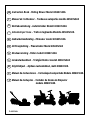 1
1
-
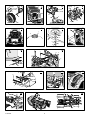 2
2
-
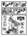 3
3
-
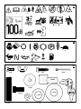 4
4
-
 5
5
-
 6
6
-
 7
7
-
 8
8
-
 9
9
-
 10
10
-
 11
11
-
 12
12
-
 13
13
-
 14
14
-
 15
15
-
 16
16
-
 17
17
-
 18
18
-
 19
19
-
 20
20
-
 21
21
-
 22
22
-
 23
23
-
 24
24
-
 25
25
-
 26
26
-
 27
27
-
 28
28
-
 29
29
-
 30
30
-
 31
31
-
 32
32
-
 33
33
-
 34
34
-
 35
35
-
 36
36
-
 37
37
-
 38
38
-
 39
39
-
 40
40
-
 41
41
-
 42
42
-
 43
43
-
 44
44
-
 45
45
-
 46
46
-
 47
47
-
 48
48
-
 49
49
-
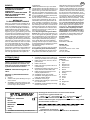 50
50
-
 51
51
-
 52
52
-
 53
53
-
 54
54
-
 55
55
-
 56
56
-
 57
57
-
 58
58
-
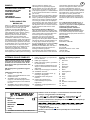 59
59
-
 60
60
-
 61
61
-
 62
62
-
 63
63
-
 64
64
-
 65
65
-
 66
66
-
 67
67
-
 68
68
-
 69
69
-
 70
70
-
 71
71
-
 72
72
-
 73
73
-
 74
74
-
 75
75
-
 76
76
-
 77
77
-
 78
78
-
 79
79
-
 80
80
-
 81
81
-
 82
82
-
 83
83
-
 84
84
-
 85
85
-
 86
86
-
 87
87
-
 88
88
-
 89
89
-
 90
90
-
 91
91
-
 92
92
-
 93
93
-
 94
94
-
 95
95
-
 96
96
-
 97
97
-
 98
98
-
 99
99
-
 100
100
-
 101
101
-
 102
102
-
 103
103
-
 104
104
-
 105
105
-
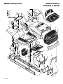 106
106
-
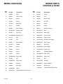 107
107
-
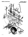 108
108
-
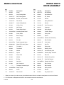 109
109
-
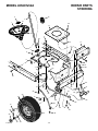 110
110
-
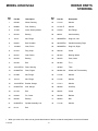 111
111
-
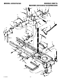 112
112
-
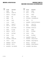 113
113
-
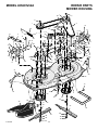 114
114
-
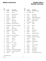 115
115
-
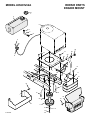 116
116
-
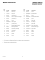 117
117
-
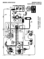 118
118
-
 119
119
-
 120
120
-
 121
121
-
 122
122
-
 123
123
-
 124
124


Hayter Mowers 405607x52A User manual
- Category
- Toys
- Type
- User manual
Ask a question and I''ll find the answer in the document
Finding information in a document is now easier with AI
in other languages
- italiano: Hayter Mowers 405607x52A Manuale utente
- français: Hayter Mowers 405607x52A Manuel utilisateur
- español: Hayter Mowers 405607x52A Manual de usuario
- Deutsch: Hayter Mowers 405607x52A Benutzerhandbuch
- Nederlands: Hayter Mowers 405607x52A Handleiding
- português: Hayter Mowers 405607x52A Manual do usuário
- dansk: Hayter Mowers 405607x52A Brugermanual
- svenska: Hayter Mowers 405607x52A Användarmanual
- suomi: Hayter Mowers 405607x52A Ohjekirja
Related papers
Other documents
-
Rover 425621x108A User manual
-
-
-
Murray 7800336 Owner's manual
-
Simplicity MANUAL, OPS/SETUP, VICTA TRACTOR SERIES V80 User manual
-
-
Snapper LT195420, CLT195420, LT23460, CLT23460, LT24520, CSLT24520, SLT23460, SLT24520, CSLT23460, CSLT24520, SLT23460FC, SLT24520FC User manual
-
Snapper LT195420, LT23460, LT24520, SLT23460, SLT24520, CLT23460, CLT24520 User manual
-
-
Snapper 7800342 Owner's manual