
BOSCH
INSTALLATION INSTRUCTION MANUAL
for
Bosch Electric Built-in
Single & Double Oven Models HBN 44../45../46..
MANUEL D'INSTALLATION
four 61ectrique Bosch encastr6,
simple et double
Models HBN 44../45../46..
Ed. 01-02
Page is loading ...

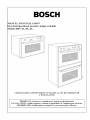
BOSCH
INSTALLATION INSTRUCTION MANUAL
for
Bosch Electric Built-in
Single & Double Oven Models HBN 44../45../46..
BEFORE YOU BEGIN, READ THESE INSTRUCTIONS COMPLETELY AND CAREFULLY
IMPORTANT: Save these instructions for the local electrical inspector's use
INSTALLER: Please leave this manual with owner for future reference.
OWNER: Please keep this manual for future reference

Table of Contents
INTRODUCTION .............................................................................................................................
TOOLS YOU WILL NEED ........................................................................................................
POWER REQUIREMENTS .......................................................................................................
CHOOSING OVEN LOCATION ...............................................................................................
STEPS FOR INSTALLATION ..................................................................................................
TECHNICAL DATA .........................................................................................................................
SINGLE OVEN ............................................................................................................................
DOUBLE OVEN ..........................................................................................................................
UNDERCOUNTER INSTALLATION ..........................................................................................
SINGLE OVEN ............................................................................................................................
WALL INSTALLATION .................................................................................................................
SINGLE OVEN ............................................................................................................................
DOUBLE OVEN ..........................................................................................................................
ELECTRICAL SUPPLY ..................................................................................................................
WIRING REQUIREMENTS ......................................................................................................
CONNECTING TO 208 VOLT CIRCUIT ...............................................................................
ELECTRICAL CONNECTIONS ...................................................................................................
3-WIRE BRANCH CIRCUIT .....................................................................................................
4-WIRE BRANCH CIRCUIT .....................................................................................................
FINAL CHECKLIST ........................................................................................................................
3
3
3
3
3
4
4
4
5
5
6
6
7
8
8
9
10
10
10
11

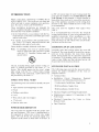
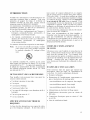
INTRODUCTION
Please read these instructions COMPLETELY
AND CAREFULLY. They will save you time and
effort and help to ensure optimum oven perform-
ance. Be sure to observe all WARNINGS.
These installation instructions are intended for
use by a qualified installer. In addition to these in-
structions the oven shall be installed:
• In the United States, in accordance with the Na-
tional Electric Code/State and Municipal codes
and/or local codes.
• In Canada, in accordance with Canadian Elec-
tric Code C22.1-1atest edition/Provincial and
Municipal codes and/or local codes.
These shall be carefully followed at all times.
Note: If installing your oven in Canada please
check to make sure that you have a model
with the UL Canadian listing mark, as
shown below:
The UL Canadian listing mark consists of the cir-
cled UL symbol preceded by the letter "C", as
shown. This should appear on the oven's rating
plate along with the UL United States listing
mark, which is the circled UL symbol above but
not preceded by the letter "C".
TOOLS YOU WILL NEED
The following tools are needed to install your new
oven:
• Tape measure and straightedge or ruler
• Pencil
• Phillips screwdriver
• Level
• Wire cutters and wire stripper
• 1" hole saw
• Hand or saber saw.
POWER REQUIREMENTS
The oven must be supplied with the proper volt-
age and frequency. The oven is manut:actured to
be connected to a three wire or four wire, single
phase, 240 volt, 60 Hz AC electrical supply on a
separate circuit fused on both sides of the line. If
a 208 volt circuit must be used, wiring inside the
oven must be modified. See Connection to a 208
Volt Circuit, in this manual. A circuit breaker or
time-delay fuse sized not to exceed the circuit rat-
ing of the appliance specified on the rating plate
located on the frame behind the door of the oven
is recommended.
The oven must be supplied with copper wires
ONLY.
It is recommended that you have the electrical
wiring and hook-up of your oven performed by a
qualified electrician. After installation is com-
plete have the electrician show you where the
main disconnect is and which of the circuit break-
ers/fuses are for the oven.
CHOOSING OVEN LOCATION
Carefully select the location where the oven will
be placed. The oven should be located for conven-
ient use in the kitchen, but away from strong
drafts. Strong drafts may be caused by open doors
or windows, or by heating and/or air conditioning
vents or fans. Make sure that electrical power can
be provided to the location selected.
STEPS FOR INSTALLATION
The following pages provide the necessary infor-
mation for proper installation of the oven ar-
ranged as tk_llows:
• Technical Data
• Installation Cutout Dimensions, Required
Clearances and Mounting instructions tk_r:
> Undercounter Installation, Single Oven
>Wall Installation, Single Oven
>Wall Installation, Double Oven
• Electrical Supply and Wiring Requirements
• Modifications required if Connecting to 208
Volt Circuit.
• Electrical Connections for 3-wire or 4-wire
Branch Circuit.
• Final Checklist.

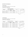
TECHNICAL DATA
SINGLE OVEN
For cutout dimensions see following sections titled:
Preparing Location
Single Oven
Models
HBL 442A UC
HBL 445A UC
HBL 446A UC
Electrical Ratings
and Maximum Connected Load
Volts Hertz Amperes
@240V/208V
240/208 60 13.5/13.6
240/208 60 13.5/13.6
240/208 60 13.5/13.6
Watts
@240V/208V
3,250/2,820
3,250/2,820
3,250/2,820
Convection
Oven
Yes
Yes
Yes
DOUBLE OVEN
For cutout dimensions see following sections titled:
Preparing Location
Double Oven
Models
HBN 452A UC
HBN 455A UC
HBN 456A UC
HBN 462A UC
HBN 465A UC
HBN 466A UC
Electrical Ratings
and Maximum Connected Load
Volts Hertz Amperes
_I!240V/208V
240/208 60 26/26
240/208 60 26/26
240/208 60 26/26
240/208 60 26/26
240/208 60 26/26
240/208 60 26/26
Watts
?I!240V/208V
6,250/5,400
6,250/5,400
6,250/5,400
6,250/5,400
6,250/5,400
6,250/5,400
Convection
Oven
(top/bottom)
Yes/No
Yes/No
Yes/No
Yes/Yes
Yes/Yes
Yes/Yes
J
J

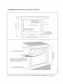
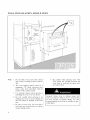
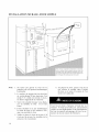
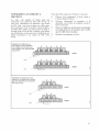
UNDERCOUNTER INSTALLATION, SINGLE
¥
co
I
i
2:
I
_ I
I
I
w
I
Oven electrical supply:
Locate junction box in
adjacent cabinet or below
bottom support surface.
25-3/8" opening width
Bottom support surface must
be solid level and able to
support at least of 150 Ibs,
toe space area
26-5/8' width of oven door frame
!/4' min. distance
between oven door
frame and adjacent
doors or drawer fronts.
Note: Decorative inserts must
maintain minimum spacing as shown.
Secure oven to cabinet using the screws
provided. Screws should be inserted through the
mounting holes in the positions indicated in the
frame (open door to see frame and mounting
holes), Do not overtighten screws,
Note: Decorative inserts must
maintain minimum spacing as shown.
Refer to and follow Notes and Warning listed under Wall Installation, Single Oven (facing page)

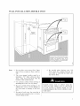
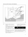
WALL INSTALLATION, SINGLE OVEN
c
_.- Electrical
o=¢ supply
junction box
25-3/8" opening width
Note: l. Do not slide oven across floor. Dam-
age to floor covering or floor could re-
sult.
2. The oven support surt:ace must be a
minimum 3/4" thick plywood plat-
form, solid, level and flush with the
bottom of the cabinet cutout.
3. Use extreme caution when moving or
installing the oven. It is very heavy.
4. Be very careful when moving or in-
stalling the oven to avoid damage to
the oven frame or damage to the cabi-
nets.
5. Be sure to level oven. An oven that is
not level may provide poor or incon-
sistent baking results.
6. Be careful when placing oven. DO
NOT pinch the conduit between the
oven back or wall and the inner cabi-
net wall or floor.
Securely t:asten oven to cabinet using the
screws provided. Failure to do so could result
in oven moving or tipping during use and
causing damage to the oven or cabinets or per-
sonal injury.

WALL INSTALLATION, DOUBLE OVEN
i
Secure oven to cabinet usingthe screws
provided. Screws should be inserted
through the mounting holes in the
positions indicated in the frame (open
door to see frame and mounting holes).
Do not overtighten screws,
Note: 1. Do not slide oven across floor. Dam-
age to floor covering or floor could re-
sult.
2. The oven support surt:ace must be a
minimum 3/4" thick plywood plat-
form, solid, level and flush with the
bottom of the cabinet cutout.
3. Use extreme caution when moving or
installing the oven. It is very heavy.
4. Be very careful when moving or in-
stalling the oven to avoid damage to
the oven frame or damage to the cabi-
nets.
5. Be sure to level oven. An oven that is
not level may provide poor or incon-
sistent baking results.
6. Be careful when placing oven. DO
NOT pinch the conduit between the
oven back or wall and the inner cabi-
net wall or floor.
Securely fasten oven to cabinet using the
screws provided. Failure to do so could result
in oven moving or tipping during use and
causing damage to the oven or cabinets or per-
sonal iniury.

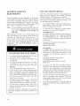
ELECTRICAL SUPPLY
Before installing the oven have a qualified electri-
cian verify that your home is provided with ade-
quate electrical service and that the addition of
the oven will not overload the branch circuit on
which it is to be installed. A separate three-wire
or four-wire single phase, 240 Volt, 60 Hz., or a
208 Volt, 60 Hz. branch circuit is required.
Note: For use with 208 V, 60 Hz supply voltage
the wiring must be modified as shown in
Connecting to 208 Volt Circuit.
For hook-up of the oven you will need to have an
approved junction box installed where it will be
easily reached through the front of the cabinet
where the oven will be located. The oven has 3
feet of conduit. Allow two to three feet of slack in
the line so that the oven can be moved if servicing
is ever necessary. DO NOT shorten the flexible
conduit.
ELECTRICAL SHOCK HAZARD
• The electrical power to the oven branch cir-
cuit must be shut off while line connections
are being made.
• Do not use an extension cord with this ap-
pliance.
• Electrical ground is required on this appli-
ance. The free end of the green wire (the
ground wire) must be connected to a suit-
able ground.
This wire must remain grounded to the
oven.
• If cold water pipe is interrupted by plastic,
non-metallic gaskets, union connections or
other insulating materials, DO NOT use for
grounding.
• DO NOT ground to a gas pipe.
• DO NOT have a fuse in the NEUTRAL or
GROUNDING circuit. A fuse in the NEU-
TRAL or GROUNDING circuit could result
in an electrical shock.
• Check with a qualified electrician if you are
in doubt as to whether the appliance is
properly grounded.
Failure to follow these instructions could re-
sult in serious injury or death.
WIRING REQUIREMENTS
When making the wire connections, use the entire
length of the conduit provided (3 feet). The con-
duit must not be cut.
Before making connections make sure the power
is off and read and observe the following:
1. A separate three-wire or four wire, single
phase, 240 Volt, 60 Hz. or 208 Volt, 60 Hz
branch circuit is required for the oven.
2. The oven must be connected with COPPER
WIRE ONLY.
3. In the United States:
Wiring must conform to the National Electri-
cal Code, ANSI/NFPA No. 70 latest edition.
You can obtain a copy of the National Elec-
trical Code by writing:
National Fire Protection Association
Batterymarch Park
Quincy, MA 02269
In Canada:
Wiring must conform to Canadian Electrical
Code C22.1- latest edition. You can obtain
copies of the Canadian Electrical Code by
writing:
Canadian Standards Association
178 Rexdale Boulevard
Rexdale (Toronto), Ontario, Canada
M9W 1R3
4. Wire size (COPPER WIRE ONLY) and con-
nections must be suitable for the rating of the
appliance per the National Electrical Code
requirements. The flexible armored cable ex-
tending from the oven should be connected
directly to the junction box.
5. The junction box should be located so as to
allow as much slack as possible between the
junction box and the oven so it can be moved
if servicing is ever required.
6. A U.L. listed conduit connector must be pro-
vided at each end of the power supply cable.

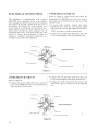
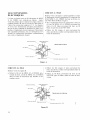
CONNECTING TO 208 V CIRCUIT
The ovens are pre-wired for connection to 240
volt, 60 Hertz supply. If connecting to a 208 volt,
60 Hz. supply a jumper must be used across two
terminals. For the double oven models there are
two jumpers, one for the upper oven and one for
the lower oven. For the single ovens there is one
jumper.
Please refer to figures below for placement of
jumper for 208 volt, 60 hertz connection.
To connect to 208 volt circuit:
1 Remove the access panel(s) located on the
back of the oven(s).
2. Loosen the first and second screws in the ter-
minal block as shown in applicable figure
above.
3. Place the metal jumper between the first
and second screws and tighten screws to
hold jumper in place.
4. Replace access panel(s).
Placing of jumper for single oven
or upper oven of double oven,
for connection to 208 volt, 60 Hz.
Before
Jumper
Jumper
After
Placing of jumper for lower oven
of double oven, for connection to
208 volt, 60 Hz.
Before
Jumper
Jumper
After

ELECTRICAL CONNECTIONS
This appliances is manufactured with a green
GROUND wire connected to the oven chassis.
After making sure that the power has been turned
off connect the flexible conduit from the oven to
the junction box using a U.L. listed conduit con-
nector. Figures A and B and the instructions pro-
vided below present the most common way of
connecting the ovens. Your local codes and ordi-
nances, of course, take precedence to these in-
structions. Complete electrical connections ac-
cording to local codes and ordinances.
3-WIRE BRANCH CIRCUIT
Refer to Figure A, where local codes allow the
connection of GROUND wire from the oven to
the branch circuit NEUTRAL wire (grey or white
colored wire):
• If local codes permit, connect the green
GROUND wire from the oven and the white
wire from the oven to the branch circuit NEU-
TRAL wire (grey or white colored wire).
• Connect the red and black leads from the oven
to the corresponding leads in the junction box.
Junction box _ CaNe from
_er Grounded Neutram
suppUy
Whitewires Red wires. _ __
Bare o_ _ "BHack wires
CaMe _ U.L.-Iisted conduit connector
from oven
Figure A.
4-WIRE BRANCH CIRCUIT
Refer to Figure B:
• Connect the green GROUND wire from the
oven to the GROUND wire in the junction box
(bare or green colored wire).
• Connect the red and black leads from the oven
to the corresponding leads in the junction box.
• Connect the white wire from the oven to the
NEUTRAL (grey or white) wire in the junction
box.
Junction box CaNe from
_-_. power suppHy
White wires
Ungrounded Neutram
BHack wires
Bare or green wures CabHe _.
from oven _ U.LMisted conduit connector
Figure B.
10

FINAL CHECK LIST
To prevent improper connections leading to dam-
age of electrical components and so voiding the
warranty, the following steps must be performed:
1. Check the electrical requirements and make
sure you have the correct electrical supply
and that the oven is properly grounded.
2. Make sure all control knobs are in the off po-
sition.
3. Turn on the power supply to the oven. When
the oven is first turned on the display will
come on showing all the call-outs and then
will become blank with the Set Clock sym-
bol in the upper right corner, as shown be-
low.
SET (_
0
@
J
.
Check power at the junction box wires using
a volt meter having a range of 0-250 VAC. If
you have installed the oven for use on 240
volt supply you should find that the voltage
reading between the black and red wires
(Line to Line) should be 220 to 240 volts. If
you have modified the oven(s) for use on 208
volt the voltage reading between the black
and red wires should be 190 to 208 volts.
5. Set the time of day by pressing the Set
Clock button and pressing the plus (+) or mi-
nus (-) button, to the right of the display to
set the correct time. Once the time is set de-
press the Set Clock button to enter the time.
A "beep" will sound and the Set Clock sym-
bol in the upper right will disappear.
6. Turn the Mode Selector knob to Manual po-
sition, the Selector knob to Bake and turn the
Temperature knob to 350 °F. The cooling
fan, the oven lights and the heat light should
come on to indicate that the oven is heating.
The heat light will turn off when the set tem-
perature (350 °F) is reached. Turn Tempera-
ture knob to off. If you have installed a dou-
ble oven repeat test tk_rsecond oven.
7. To check the other oven functions refer to
the Using the Oven Controls section of the
Use and Care Manual.
8. If the oven is working properly turn the Se-
lector knob(s) and the Temperature Control
knob(s) to their off positions and turn off the
power supply to the oven.
9. Place the cover on the junction box and
make sure the cover is securely fastened and
turn on the power to the oven.
10. Leave these INSTALLATION instructions
as well as the USE AND CARE MANUAL
with the owner.
11
Page is loading ...
Page is loading ...

Table des mati_res
INTRODUCTION .............................................................................................................................
OUTILS DONT VOUS AUREZ BESOIN ................................................................................
SPECIFICATIONS ELECTRIQUES REQUISES ....................................................................
CHOIX DE L'EMPLACEMENT DU FOUR ............................................................................
ETAPES DE L'INSTALLATION ..............................................................................................
DONNI_ES TECHNIQUES ..............................................................................................................
FOUR SIMPLE ............................................................................................................................
FOUR DOUBLE ..........................................................................................................................
INSTALLATION SOUS LE COMPTOIR ....................................................................................
FOUR SIMPLE ...........................................................................................................................
INSTALLATION MURALE ...........................................................................................................
FOUR SIMPLE ............................................................................................................................
FOUR DOUBLE ..........................................................................................................................
ALIMENTATION EN I_LECTRICITI_ ........................................................................................
FILS t_LECTRIQUES REQUIS .................................................................................................
CONNEXION A UN CIRCUIT A 208 VOLTS .......................................................................
LES CONNEXIONS I_LECTRIQUES ..........................................................................................
CIRCUIT )t 3 FILS .....................................................................................................................
CIRCUIT )t 4 FILS .....................................................................................................................
LISTE DE ¥1_RIFICATION FINALE ..........................................................................................
15
15
15
15
15
16
16
16
17
17
18
18
19
20
20
21
22
22
22
23
14
Page is loading ...
Page is loading ...
Page is loading ...
Page is loading ...
Page is loading ...
Page is loading ...
Page is loading ...
Page is loading ...
Page is loading ...
Page is loading ...
Page is loading ...
Page is loading ...
-
 1
1
-
 2
2
-
 3
3
-
 4
4
-
 5
5
-
 6
6
-
 7
7
-
 8
8
-
 9
9
-
 10
10
-
 11
11
-
 12
12
-
 13
13
-
 14
14
-
 15
15
-
 16
16
-
 17
17
-
 18
18
-
 19
19
-
 20
20
-
 21
21
-
 22
22
-
 23
23
-
 24
24
-
 25
25
-
 26
26
-
 27
27
-
 28
28


Bosch HBN446AUC Installation guide
- Category
- Ovens
- Type
- Installation guide
Ask a question and I''ll find the answer in the document
Finding information in a document is now easier with AI
in other languages
- français: Bosch HBN446AUC Guide d'installation
Related papers
-
Bosch HBN 465A UC User manual
-
-
-
-
Bosch 44 User manual
-
-
-
-
Bosch HBL755AUC(00) Installation guide
-
Other documents
-
Smeg SOU130S1 Installation guide
-
Fulgor Milano F1SP24S1 Installation guide
-
Haier HCW3460AES Installation guide
-
Fulgor F4SP30S1 Installation guide
-
Verona VEBIG30NE Owner's manual
-
-
Whirlpool MMW9730AW01 Installation guide
-
KitchenAid KEHU309SSS06 Installation guide
-
Maytag CWE5800ACB - 24 Inch Double Electric Wall Oven Installation guide
-
Whirlpool GBD307PRQ03 Installation guide