16-Bay Media Converter Chassis
12 User’s Manual
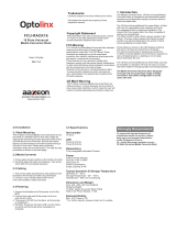
Ethernet data
Ethernet Connection in full duplex
mode
Steady
Fdx stands for FULL-DUPLEX
Flashing Collision occurred
Fdx
Off Ethernet Connection in half-duplex
mode
Ethernet over VDSL
Green The VDSL port transmitting/receiving
at 1Mbps, up to 1900M
1
Amber The VDSL port transmitting/receiving
at 3Mbps, up to 1700M
Green The VDSL port transmitting/receiving
at 5Mbps, up to 1600M
2
Amber The VDSL port transmitting/receiving
at 10Mbps, up to 1500M
Green The VDSL port transmitting/receiving
at 15Mbps, up to 1400M
3
Amber The VDSL port transmitting/receiving
at 20Mbps, up to 1000M
Green The VDSL port transmitting/receiving
at 25Mbps, up to 800M
4
Amber The VDSL port transmitting/receiving
at 30Mbps, up to 600M
Rmt Steady The device operates in remote mode
Loc Steady The device operates in local mode
Err Steady Error occurred
Lnk Steady A valid VDSL connection established
Step 1: To install a media converter onto any of the carriers, you have to unscrew the carrier from the desired bay first.
Step 2: Fit the media converter onto the carrier.
Step 3: When the media converter is completely seated onto the carrier, insert the carrier to the guide rails of the bay slot.
Step 4: Carefully slide in the carrier until it is fully and firmly fitted to the power socket. Fasten the screws on the carrier.
L
i. The chassis is designed to house only the proprietary media converters.
ii. Never insert any media converter into the chassis directly without using the supplied carriers. These carriers allow secure and
consistent placement of the media converters into the chassis’ backplane without causing any damage.
iii. For details, please refer to the User’s Manual for media converters.