Pulsar blackbox 134 User manual
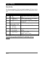
- Category
- Measuring, testing & control
- Type
- User manual

blackbox 134
INSTRUCTION MANUAL


BLACK BOX LEVEL 134 (SEVENTH EDITION REV 3)
February 2018
Part Number M-134-0-007-3P
COPYRIGHT
© Pulsar Process Measurement Limited, 2003 -18. All rights reserved. No part of this publication may be
reproduced, transmitted, transcribed, stored in a retrieval system, or translated into any language in any
form without the written permission of Pulsar Process Measurement Limited.
WARRANTY AND LIABILITY
Pulsar Process Measurement Limited guarantee for a period of 2 years from the date of delivery that it will
either exchange or repair any part of this product returned to Pulsar Process Measurement Limited if it is
found to be defective in material or workmanship, subject to the defect not being due to unfair wear and
tear, misuse, modification or alteration, accident, misapplication or negligence.
DISCLAIMER
Pulsar Process Measurement Limited gives nor implies any process guarantee for this product, and shall
have no liability in respect of any loss, injury or damage whatsoever arising out of the application or use of
any product or circuit described herein.
Every effort has been made to ensure accuracy of this documentation, but Pulsar Process Measurement
Limited cannot be held liable for any errors.
Pulsar Process Measurement Limited operates a policy of constant development and improvement and
reserves the right to amend technical details as necessary.
The blackbox shown on the cover of this manual is used for illustrative purposes only and may not be
representative of the actual blackbox supplied.
TECHNICAL ENQUIRIES
Please contact Pulsar Process Measurement Limited for technical support.
COMMENTS AND SUGGESTIONS
If you have any comments or suggestions about this product, then please contact:
Pulsar Process Measurement Limited
Pulsar Process Measurement Inc.
Cardinal Building
Enigma Business Centre
Sandy’s Road
Malvern
Worcestershire
WR14 1JJ
United Kingdom
PO Box 5177
Niceville
FL 32578 - 5177
USA
Tel: + 44 (0) 1684 891371
Fax: + 44 (0) 1684 575985
Tel: + 1 850 279 4882
Fax: + 1 850 279 4886
Web Site: https://www.pulsar-
pm.com/instrumentation
e-mail: info@pulsar-pm.com (general
information)
e-mail: support@ pulsar-pm.com (product
support)
Web Site: https://www.pulsar-
pm.com/instrumentation
e-mail: info.usa@pulsar-pm.com (general
information)
e-mail: support.usa@ pulsar-pm.com (product
support)


Contents
Chapter 1 Start Here… ...................................................................................................................................................1
About this Manual ......................................................................................................................................................1
About the blackbox range .........................................................................................................................................2
Functional Description ..............................................................................................................................................3
Product Specification .................................................................................................................................................4
EU Declaration of Conformity .................................................................................................................................6
Chapter 2 Installation ......................................................................................................................................................7
Power Supply Requirements ....................................................................................................................................7
Location .......................................................................................................................................................................7
Dimensions..................................................................................................................................................................8
Standard Enclosure ............................................................................................................................................8
Large Enclosure (optional) ............................................................................................................................ 10
Terminal Connection Details................................................................................................................................. 12
Power ................................................................................................................................................................ 13
Transducer........................................................................................................................................................ 13
Relay Outputs .................................................................................................................................................. 14
RS232 Serial Interface ................................................................................................................................... 14
RS485 Serial Interface ................................................................................................................................... 15
Voltage Selector and Fuse Location ..................................................................................................................... 16
Preparation for Operation ....................................................................................................................................... 17
Maintenance ............................................................................................................................................................. 17
Chapter 3 How To Use Your blackbox Level System .......................................................................................... 19
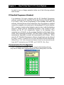
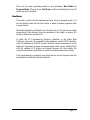
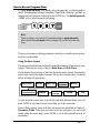
PC Handheld Programmer (Standard) ................................................................................................................. 19
Communication Port Configuration ............................................................................................................ 19
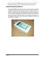
Handheld Communicator (Optional) ................................................................................................................... 20
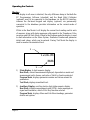
On board integral Keypad and Display (Optional) ............................................................................................ 21
Operating the Controls ........................................................................................................................................... 22
Display .............................................................................................................................................................. 22
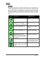
Keypad.............................................................................................................................................................. 23
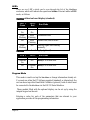
Run Mode ................................................................................................................................................................. 25
LED’s ............................................................................................................................................................... 26
Program Mode ......................................................................................................................................................... 26
How to Access Program Mode..................................................................................................................... 27
Test Mode ................................................................................................................................................................. 29
LED’s ............................................................................................................................................................... 30
Using the RS232 Serial Interface .......................................................................................................................... 30
Parameter Defaults .................................................................................................................................................. 31
Factory Defaults .............................................................................................................................................. 31
Chapter 4 Programming Guide .................................................................................................................................. 33
Level .......................................................................................................................................................................... 33
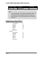
Example 1 Level Measurement .................................................................................................................... 33
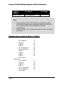
Example 2 Alternating Control (pump down) ........................................................................................... 35
Volume (Optional) .................................................................................................................................................. 37
Example 3 Volume Application ................................................................................................................... 37
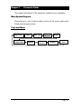
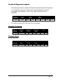
Chapter 5 Parameter Guide ......................................................................................................................................... 39
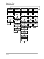
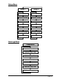
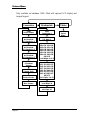
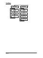
Menu System Diagrams ......................................................................................................................................... 39
Top Level Menu.............................................................................................................................................. 39
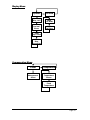
Application Menu ........................................................................................................................................... 40
Relays Menu .................................................................................................................................................... 41
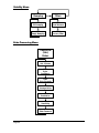
Data Logs Menu.............................................................................................................................................. 41

Volume Menu ................................................................................................................................................. 42
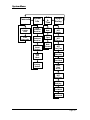
Display Menu .................................................................................................................................................. 43
Compensation Menu ...................................................................................................................................... 43
Stability Menu ................................................................................................................................................. 44
Echo Processing Menu................................................................................................................................... 44
System Menu ................................................................................................................................................... 45
Test Menu ........................................................................................................................................................ 46
Parameter Listing .................................................................................................................................................... 47
Application Parameters .......................................................................................................................................... 47
Operation .......................................................................................................................................................... 47
Dimensions ...................................................................................................................................................... 48
Device Set Up.................................................................................................................................................. 50
Remote Alarm ................................................................................................................................................. 51
SMS Time ........................................................................................................................................................ 53
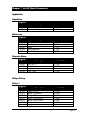
Relay Parameters ..................................................................................................................................................... 54
Relay Type ....................................................................................................................................................... 54
Alarms .............................................................................................................................................................. 55
Control .............................................................................................................................................................. 57
Data Log Parameters .............................................................................................................................................. 60
Temperature ..................................................................................................................................................... 60
Volume (Optional) .................................................................................................................................................. 61
Conversion ....................................................................................................................................................... 61
Breakpoints ...................................................................................................................................................... 64
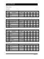
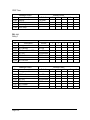
Tables................................................................................................................................................................ 66
Display Parameters ................................................................................................................................................. 66
Options ............................................................................................................................................................. 66
Failsafe.............................................................................................................................................................. 67
Compensation Parameters ..................................................................................................................................... 67
Offset ................................................................................................................................................................ 67
Temperature ..................................................................................................................................................... 68
Stability Parameters ................................................................................................................................................ 68
Damping ........................................................................................................................................................... 68
Filters ................................................................................................................................................................ 69
Echo Processing Parameters .................................................................................................................................. 69
Transducer Status ............................................................................................................................................ 69
System Parameters .................................................................................................................................................. 70
Passcode ........................................................................................................................................................... 70
System Information ........................................................................................................................................ 71
Date & Time .................................................................................................................................................... 71
Daylight Saving Time .................................................................................................................................... 72
Test Parameters........................................................................................................................................................ 76
Simulation ........................................................................................................................................................ 76
Hardware .......................................................................................................................................................... 77
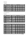
Chapter 6 Modbus ........................................................................................................................................................... 78
Device Set Up .......................................................................................................................................................... 78
Protocol Basics ........................................................................................................................................................ 79
Modbus ..................................................................................................................................................................... 79
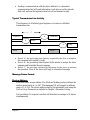
Typical Transmission Line Activity ..................................................................................................................... 80
Message Frame Format .......................................................................................................................................... 80
Device Address ............................................................................................................................................... 80
Parameter Address .......................................................................................................................................... 81
Function Codes ............................................................................................................................................... 81
Request & Response Conventions ....................................................................................................................... 82
Parameter Resolution and Scaling................................................................................................................ 82
Example 1 Write date to Modbus................................................................................................................. 83
Example 2 Taking temperature reading ...................................................................................................... 83

Error Checking ................................................................................................................................................ 84
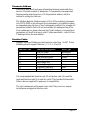
Message Timings .................................................................................................................................................... 86
Mode of Transmission ................................................................................................................................... 86
Wait Period ...................................................................................................................................................... 86
Latency ............................................................................................................................................................. 87
Message Transmission Time ........................................................................................................................ 87
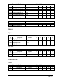
Modbus Functions ................................................................................................................................................... 88
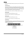
Function 1: Read Output Status ............................................................................................................................ 88
Example: Query: reading relay 2 to 4 .......................................................................................................... 88
Function 2: Read Input Status .............................................................................................................................. 89
Example: Query: reading digital inputs 3-7 ................................................................................................ 89
Function 3: Read Holding Registers (Static Parameters) .................................................................................. 90
Example: Query: reading parameter P856 .................................................................................................. 90
Function 4: Read Input Registers (Common Dynamic Variables).................................................................. 91
List of Common Dynamic Variables........................................................................................................... 91
Example: Query: reading level 1 (current level on transducer 1) ............................................................ 92
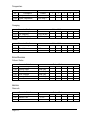
Function 5: Force Single Coil................................................................................................................................ 93
Example: Query: Force coil 2 to be ON ...................................................................................................... 93
Function 6: Write Single Register (Static Parameters) ...................................................................................... 94
Example: Query: writing to P100 = 1 .......................................................................................................... 94
Function 8: Diagnostic Loopback......................................................................................................................... 95
Example: Command....................................................................................................................................... 95
Example: Reply ............................................................................................................................................... 95
Function 16: Write Multiple Registers (Static Parameters) .............................................................................. 96
Example: Query: writing to P100 = 1, P101=2 .......................................................................................... 96
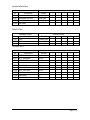
Chapter 7 List Of Static Parameters............................................................................................................................ 97
Application ............................................................................................................................................................... 97
Operation .......................................................................................................................................................... 97
Distances .......................................................................................................................................................... 97
Remote Alarm ................................................................................................................................................. 97
Relays Set up............................................................................................................................................................ 97
Relay 1 .............................................................................................................................................................. 97
Relay 2 .............................................................................................................................................................. 98
Data Logs ................................................................................................................................................................. 98
Temperature Log ............................................................................................................................................ 98
Volume ..................................................................................................................................................................... 98
Conversion ....................................................................................................................................................... 98
Volume Break points...................................................................................................................................... 99
Display .................................................................................................................................................................... 100
Options ........................................................................................................................................................... 100
Fail Safe .......................................................................................................................................................... 100
Compensation ........................................................................................................................................................ 101
Offset .............................................................................................................................................................. 101
Temperature ................................................................................................................................................... 101
Stability ................................................................................................................................................................... 101
Damping ......................................................................................................................................................... 101
Filters .............................................................................................................................................................. 101
Echo Processing .................................................................................................................................................... 101
Transducer 1 .................................................................................................................................................. 101
System ..................................................................................................................................................................... 102
Passcode ......................................................................................................................................................... 102
System Information ...................................................................................................................................... 102
Date and Time ............................................................................................................................................... 102
Daylight Saving............................................................................................................................................. 102
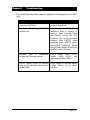
Chapter 8 Troubleshooting ....................................................................................................................................... 103

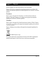
Chapter 9 Disposal ..................................................................................................................................................... 105
Parameter Record .......................................................................................................................................................... 107

Page 1
Chapter 1 Start Here…
Congratulations on your purchase of a Pulsar blackbox 134 Level Comms
(Modbus) System. This quality system has been developed over many years
and represents the latest in high technology ultrasonic level measurement and
control.
It has been designed to give you years of trouble free performance, and a few
minutes spent reading this operating manual will ensure that your installation
is as simple as possible.
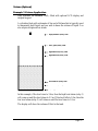
About this Manual
It is important that this manual is referred to for correct installation and
operation.
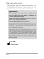
There are various parts of the manual that offer additional help or information
as shown.
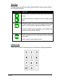
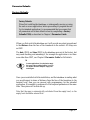
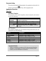
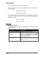
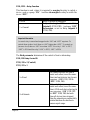
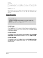
Tips
Tip
At various parts of
this manual you will
find tips to help you.
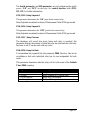
Additional Information
Additional Information
At various parts of the manual, you will find
sections like this that explain specific things in
more detail.
References
See Also
References to other parts of the manual

Page 2
About the blackbox range
The Pulsar blackbox is a non-contact Level Control System. It has been
designed to provide a new concept in low cost maintenance-free fit and forget
level measurement without any compromise on performance.
The blackbox is ideally suited to applications where level monitoring,
reporting, control or logging is required, with or without the need for a local
display.
The blackbox level system is available in a variety of different versions
offering a wide choice of output options.
The blackbox is very easy to use and may be calibrated quickly and simply
via a laptop, using the software supplied with the unit, or alternatively by
using the optional hand held calibrator, which connects to the unit via the
RS232 interface, and provides an on board LCD display. Certain models are
also available with an optional LCD display and integral keypad fitted.
All models of the blackbox range can be used with any of the extensive range
of Pulsar dB transducers for distances up to 40m (131ft).
The blackbox range is designed to provide you with highly reliable
measurement in a robust and functional package that is easy to use and low in
cost.

Page 3
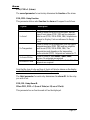
Functional Description
The blackbox ultrasonic Level System sends a transmit pulse to the
transducer, which emits an ultrasonic pulse perpendicular to the transducer
face, and the returned echo is sent back to the BlackBox. The time taken to
receive the echo is measured and the distance from the transducer face to the
surface being monitored is calculated.
The blackbox utilises the unique DATEM software (Digital Adaptive
Tracking of Echo Movement). This is a unique digital mapping technique
developed especially for Pulsar’s range of ultrasonic level and control
systems. It gives the system edge when identifying the “true target level” in
the face of competing echoes from pipes, pumps or other obstructions.
The blackbox can measure from 0.125m (0.41ft) to 40m (131 feet) from the
transducer to the surface being monitored, dependent on the application and
transducer used.
The blackbox can measure level, space or distance and provide a
representative output. When fitted with the optional display and keyboard
it can also measure and provide an output representative of volume. There are
two user definable relays, with individual setpoints, which can be
programmed to activate alarms, a RS232 port, so that the BlackBox can be
programmed and RS 485 which provides communication so that the unit can
be monitored remotely by a PC or other equipment.
The blackbox can be programmed either by PC, via the RS 232 Serial
Interface, using the supplied software (standard) or by hand held calibrator
(optional) which is connected to the blackbox via the RS 232 interface.
Those units fitted with the optional on board display can be programmed via
the integral keyboard.
All the parameters are stored in non-volatile memory, so are retained in the
event of power interruption.

Page 4
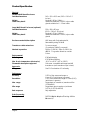
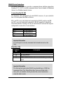
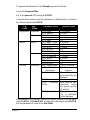
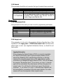
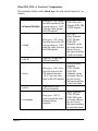
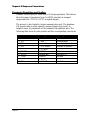
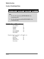
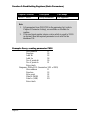
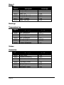
Product Specification
Physical
Standard Wall Mount Enclosure
Outside dimensions 143 x 150 x 63.5 mm (5.63 x 5.91 x 2.5
inches)
Weight Nominal 0.65 kg (1.4lbs)
Cable entry detail underside fitted with 3 x M20, nylon cable
glands suitable for 6 – 12mm cable
Large Wall Mount Enclosure (optional)
Outside dimensions 130 x 180 x 85 mm
(5.12 x 7.09 x 3.35 inches)
Weight Nominal 0.75 kg (1.65lbs)
Cable entry detail underside fitted with 5 x M20, nylon cable
glands
Enclosure material/description ABS base with Polycarbonate lid,
flammability rating UL94HB
Transducer cable extensions 2-core screened
(2 conductor 20AWG screened)
Nominal separation 1000 m (3,280 ft.). 500m (1,640 ft.) for
dBR16. For greater distances consult
Pulsar
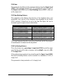
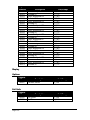
Environmental
IP Rating IP66 with display
IP67 Without display
Max. & min. temperature (electronics) -20 ºC to +50 ºC (-4ºF to 120ºF)
Flammable atmosphere approval Safe area: compatible with approved dB
transducers (see transducer spec' sheet)
Approvals
CE approval See EU Declaration of Conformity
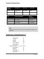
Performance
Accuracy 0.25% of the measured range or
6 mm (0.24”) (whichever is greater)
Resolution 0.1% of the measured range or 2 mm (0.08”)
(whichever is greater)
Max. range Dependant on transducer (maximum 40m
(131ft) dB40)
Min. range Dependent upon transducer (minimum
0.077m (0.252 ft) dBR16)
Rate response fully adjustable
Echo Processing
Description DATEM (Digital Adaptive Tracking of Echo
Movement)

Page 5
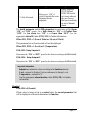
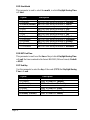
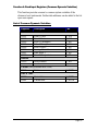
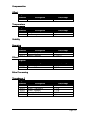
Outputs
Serial Port (Digital Output) RS232 for programming and data extraction
RS 485 providing communications
Volt free contacts, number and rating 2 form "C" (SPDT) rated at 2A at 240V AC
Display (optional) 2 x 12 alpha numeric
Programming
PC programming (standard) via RS232 using supplied software
Remote programming (optional) via RS232 using optional hand held
calibrator
On board programming (optional) via integral keypad
Programming security via passcode (user selectable and
adjustable)
Programmed data integrity via non-volatile RAM
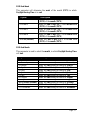
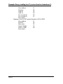
Supply
Power supply 115VAC +5% / -10% 50/60 Hz,
230VAC + 5% / -10% 50/60 Hz,
dc 10 - 28V
10W maximum power (typically 5W)
Fuses 50 mA at 230 VAC (fitted as standard)
100 mA at 115 VAC
Remote Communicator
Power Supply Power supplied via BlackBox RS232
interface.
Pulsar Process Measurement Limited operates a policy of constant development and
improvement and reserve the right to amend technical details as necessary.

Page 6
EU Declaration of Conformity

Page 7
Chapter 2 Installation
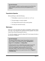
Power Supply Requirements
The BlackBox can operate from AC supply or from a DC battery. The AC is
115V +5%/-10% 50/60Hz or 230V +5%/-10% 50/60Hz, depending on the
position of the selector switch. The DC is 10-28V. In all cases the BlackBox
will typically consume 5W of power, with a maximum of 10W.
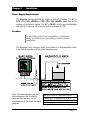
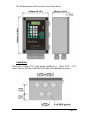
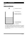
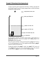
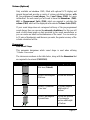
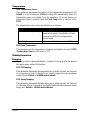
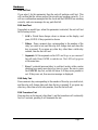
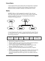
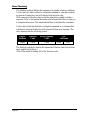
Location
All electronic products are susceptible to electrostatic
shock, so follow proper grounding procedures during
installation.
The blackbox level controller must be mounted in a non-hazardous (safe)
Area, and the transducer fitted in the hazardous area.
Note: The blackbox shown in the
above diagram is for illustrative
purposes only and may not be
representative of the actual blackbox
supplied.
FM APPROVED TRANSDUCERS
Class I, Div. 1, Group A, B, C & D
Class II, Div. 1, Group E, F & G
Class III

Page 8
When choosing a location to mount the enclosure, bear in mind the following:
• Ensure that the blackbox is installed in a “Safe”, non-hazardous,
area.
• Easy access to the enclosure is maintained.
• The mounting surface is vibration-free.
• The ambient temperature is between -20ºC and 50ºC (-4ºF and
120ºF).
• There should be no high voltage cables or inverters close by.
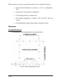
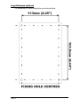
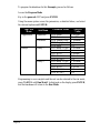
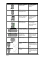
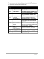
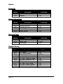
Dimensions
Standard Enclosure
The dimensions of the mounting holes are as shown below.

Page 9
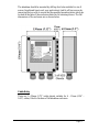
The blackbox should be mounted by drilling four holes suitable for size 8
screws (length and type to suit your application) And fix all four screws by
removing the top cover to access the pre-moulded mounting holes which are
located in the base of the enclosure under the lid retaining screws. The full
dimensions of the enclosure are as shown below.
Cable Entry
There are 3 x 20mm (0.79") cable glands, suitable for 6 – 12mm (0.24" –
0.63") cables, fitted to the base of the blackbox enclosure.

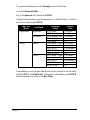
Page 10
Large Enclosure (optional)
The dimensions of the mounting holes are as shown below.

Page 11
The full dimensions of the enclosure are as shown below.
Cable Entry
There are 5 x 20mm (0.79") cable glands, suitable for 6 – 12mm (0.24" – 0.63")
cables, fitted to the base of the fitted to the base of the BlackBox enclosure.

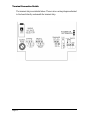
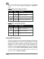
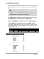
Page 12
Terminal Connection Details
The terminal strip is as detailed below. There is also a wiring diagram attached
to the board directly underneath the terminal strip.
Page is loading ...
Page is loading ...
Page is loading ...
Page is loading ...
Page is loading ...
Page is loading ...
Page is loading ...
Page is loading ...
Page is loading ...
Page is loading ...
Page is loading ...
Page is loading ...
Page is loading ...
Page is loading ...
Page is loading ...
Page is loading ...
Page is loading ...
Page is loading ...
Page is loading ...
Page is loading ...
Page is loading ...
Page is loading ...
Page is loading ...
Page is loading ...
Page is loading ...
Page is loading ...
Page is loading ...
Page is loading ...
Page is loading ...
Page is loading ...
Page is loading ...
Page is loading ...
Page is loading ...
Page is loading ...
Page is loading ...
Page is loading ...
Page is loading ...
Page is loading ...
Page is loading ...
Page is loading ...
Page is loading ...
Page is loading ...
Page is loading ...
Page is loading ...
Page is loading ...
Page is loading ...
Page is loading ...
Page is loading ...
Page is loading ...
Page is loading ...
Page is loading ...
Page is loading ...
Page is loading ...
Page is loading ...
Page is loading ...
Page is loading ...
Page is loading ...
Page is loading ...
Page is loading ...
Page is loading ...
Page is loading ...
Page is loading ...
Page is loading ...
Page is loading ...
Page is loading ...
Page is loading ...
Page is loading ...
Page is loading ...
Page is loading ...
Page is loading ...
Page is loading ...
Page is loading ...
Page is loading ...
Page is loading ...
Page is loading ...
Page is loading ...
Page is loading ...
Page is loading ...
Page is loading ...
Page is loading ...
Page is loading ...
Page is loading ...
Page is loading ...
Page is loading ...
Page is loading ...
Page is loading ...
Page is loading ...
Page is loading ...
Page is loading ...
Page is loading ...
Page is loading ...
Page is loading ...
Page is loading ...
Page is loading ...
Page is loading ...
Page is loading ...
Page is loading ...
Page is loading ...
Page is loading ...
Page is loading ...
Page is loading ...
-
 1
1
-
 2
2
-
 3
3
-
 4
4
-
 5
5
-
 6
6
-
 7
7
-
 8
8
-
 9
9
-
 10
10
-
 11
11
-
 12
12
-
 13
13
-
 14
14
-
 15
15
-
 16
16
-
 17
17
-
 18
18
-
 19
19
-
 20
20
-
 21
21
-
 22
22
-
 23
23
-
 24
24
-
 25
25
-
 26
26
-
 27
27
-
 28
28
-
 29
29
-
 30
30
-
 31
31
-
 32
32
-
 33
33
-
 34
34
-
 35
35
-
 36
36
-
 37
37
-
 38
38
-
 39
39
-
 40
40
-
 41
41
-
 42
42
-
 43
43
-
 44
44
-
 45
45
-
 46
46
-
 47
47
-
 48
48
-
 49
49
-
 50
50
-
 51
51
-
 52
52
-
 53
53
-
 54
54
-
 55
55
-
 56
56
-
 57
57
-
 58
58
-
 59
59
-
 60
60
-
 61
61
-
 62
62
-
 63
63
-
 64
64
-
 65
65
-
 66
66
-
 67
67
-
 68
68
-
 69
69
-
 70
70
-
 71
71
-
 72
72
-
 73
73
-
 74
74
-
 75
75
-
 76
76
-
 77
77
-
 78
78
-
 79
79
-
 80
80
-
 81
81
-
 82
82
-
 83
83
-
 84
84
-
 85
85
-
 86
86
-
 87
87
-
 88
88
-
 89
89
-
 90
90
-
 91
91
-
 92
92
-
 93
93
-
 94
94
-
 95
95
-
 96
96
-
 97
97
-
 98
98
-
 99
99
-
 100
100
-
 101
101
-
 102
102
-
 103
103
-
 104
104
-
 105
105
-
 106
106
-
 107
107
-
 108
108
-
 109
109
-
 110
110
-
 111
111
-
 112
112
-
 113
113
-
 114
114
-
 115
115
-
 116
116
-
 117
117
-
 118
118
-
 119
119
-
 120
120
-
 121
121


Pulsar blackbox 134 User manual
- Category
- Measuring, testing & control
- Type
- User manual
Ask a question and I''ll find the answer in the document
Finding information in a document is now easier with AI
Related papers
-
Pulsar blackbox 130 User manual
-
-
-
-
-
-
-
-
-