Pass and Seymour 1200_Cable_Reel_IS (PDF) Installation guide
- Type
- Installation guide

No: 341238 – 09/18
Catalog Number(s) • Numéro(s) de Catalogue • Les Numéros de Catalogue: CR12
Country of Origin: Made in USA • Pays d’origine: Fabriqué en USA • País de origen: Hecho en USA
Pass & Seymour
®
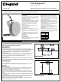
1200 Series Cable Reel
Installation Instructions • Notice d’Installation • Instrucciones de Instalación
READ & SAVE THESE INSTRUCTIONS!
Electrical Warnings
Properly ground this equipment before use in accordance with
both the National Electric Code and local electrical codes and
ordinances.
Disconnect the electrical power from the cable reel before any
service functions are performed.
Do not use this cable reel for loads greater than the current rating
listed on the label and voltage greater than 300V with SJOW-A cable
OR 600V with SOW-A cable. The ampacity (current) rating of the
cable must be in accordance with the National Electric Code.
Electrical wiring on the reel must be done by a qualified
electrician.
Feeder Cord Connection
Power supply should have overcurrent protection to prevent
overheating of the reel and cable.
Operational Warnings
Exercise care when handling the cable reel during normal
operation. This cable reel has a rotating spool powered by springs
under tension.
Do not allow cable to retract without restraining the retraction
speed.
Do not disassemble the spring motor for any reason. Serious
personal injury could result. This cable reel is equipped with
springs under tension. Contact the factory for assistance:
1-800-223-4185
1-877-BY-LEGRAND
Maintenance Warnings
Do not use cable different from that for which the reel is intended.
Changes in diameter, weight per foot, length of cable or flexibility
will affect the operation of the reel.
Mounting hardware and fasteners should be installed to maintain
tightness under vibration and checked periodically to assure
tightness.
Overhead installation mountings should be such that the reel
is not suspended by bolts in tension. A safety chain or cable is
strongly recommended to minimize damage and/or possible injury
in the event of mounting failure.
WARNING: Modification of this equipment may cause excessive
wear and will void the warranty. Contact the manufacturer
regarding changes or modifications of equipment which could
affect reliability or safety.
Listed cable reels are intended for General/Commercial/Industrial
use and are provided with permanent mounting means. They
must be wired by a qualified electrician.
UL/CSA listed cable per rating of reel, as noted on the
identification label, to be used for the supply cable (if flexible cable
is used) and for the load end cable (active cable).
Electrical Rating
Reels equipped with cable are rated and should not be used at
voltages and/or amperes above the rating on the reel. Please
consult factory prior to making any changes in volts and amps of
cable, as a change could affect reliability or safety.
INSTALLATION INSTRUCTIONS
This Cable Reel is factory wired with cable size and length specified at time of
purchase. If not included, the load end must be installed per National Electrical
Code, and local electrical codes and ordinances.
APPLICATION TYPES
Stretch Applications
The cable is suspended without any intermediate support. Stretch reels generally
require a line pull equal to two times the weight of the cable, which allows approximately
10% sag at full extension. On long applications where sag cannot be tolerated, it is
sometimes desirable to put supports at intervals of 5 to 10 feet. See Figure 1.
Lift Applications
The cable is lifted vertically in lift applications. The reel is normally designed to handle
only the total weight of the cable. Some lift applications may require a ball stop and
ratchet to control the length of cable to be retracted. See Figure 2.
Drag Applications
The reel is mounted on a stationary object and is required to drag the cable over the
surface to the reel. The cable is supported by the ground or some type of cable tray. A
ball stop may be required. All 1200 Series reels sold with cable have a ball stop installed
on the reel. See Figure 3.
Retrieve Applications
The reel is mounted on the moving object and winds up or pays out the cable as the
machine approaches or moves away from the fixed end. See Figure 4.
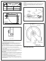
MOUNTING
Standard Mounting
The reel may be mounted by bolting the base to any flat surface which is structurally
sound enough to support it and the forces of winding and unwinding the cable.
The spool drum must rotate on a horizontal axis.
The reel should be oriented so that the cable extends perpendicular to the rotation
of the spool. The cable deflection should not exceed 15° to either side of center. See
Figure 5.
If deflection is constant to either side of the reel and operation is impaired, re-mount the
reel. See Figure 5.
If the total angle of deflection exceeds 30° a Pivot Base should be used, otherwise
excessive cable wear and unreliable operation will result.
We recommend a safety chain for all overhead installations. Attach the safety chain
using the 0.39 hole provided in the base.
UNSUPPORTED
Cable
AWG / # of Cond.
Ampacity
16/3 10.0
16/4 8.0
14/3 15.0
14/4 12.0
12/3 20.0
12/4 16.0
A
S
H
or
Figure 1 Stretch Application
Figure 2 Lift Application
A

Pivot Base Mounting (Optional Accessory)
All 1200 Series Cable Reels can be furnished with a pivot base to allow
the reel to rotate and keep the extended cable perpendicular to the
application. See Figure 6.
The PVB Pivot Base will rotate up to 345°. Travel can be limited to 90°,
180°, or 270° by installing an additional roll pin in the appropriate available
hole.
A pivot base is required for carousel or loop track applications.
When a pivot base is used the reel must be mounted horizontally (“ceiling”
or “floor” mounted).
The Roller Guide should be mounted to require the cable to travel
perpendicular to the axis of rotation. This will guard against cable twisting
and ensure effective swivel action from the pivot base.
Roller Guides
All 1200 Series units are equipped with a roller guide. The guide’s function
is to center the cable on the spool and to help the reel wrap cable more
evenly. See Figure 7.
The cable should not bear against either end of the spool during winding
as this will tend to inhibit level winding of the cable.
The guide should be secured at the best of twelve possible positions so
that a minimum change of direction occurs at the guide; otherwise, cable
life will be reduced.
A max 15° angle from guide arm center to cable pay out from reel is
suggested.
The guide arm is shipped attached to the reel. The guide must be located
and secured in the most appropriate position with the 5/16-18 x 5/8” hex
head screw and lock washer provided, prior to making any electrical
connections.
15
O
15
O
Figure 5 Cable Deection with Roller Guide
h1
l2
l1
or
Figure 3 Drag Application
A
H
Figure 4 Retrieve Application
SUPPORTED
MOBILE
MOBILE
SUPPORTED
Figure 6
Figure 7 Roller Guide Locations
(4 of 12 possible positions shown)

Spring Tension Adjustment
To assure that the cable will retract properly and operate under the correct
tension, the reel should be tested.
1. Install cable on drum but do not connect the free end of cable. Securely
mount reel before testing.
2. Pull the cable out approximately 20 - 30 feet and allow it to rewind. This
procedure should be repeated 5 to 10 times in order to set the spring.
3. Walk the cable back to the reel during the spring tension adjusting process.
WARNING: Do not allow cable to retract without restraining the retraction
speed. Always maintain two full cable wraps on drum at maximum cable
extension, size cable accordingly.
4. With all the cable wound on the reel, grasp the end of the cable and rotate
the drum and cable together in a clockwise direction in order to pre-tension
the spring. Generally, one full turn is adequate for most applications. Use no
more than two full turns for pre-tension. See Figure 9.
5. Feed the end of the cable through the cable guide and pull the cable out the
required length.
NOTE: The number of spool revolutions including the pre-tension turns
should not exceed 26 full turns on models with K Spring Motor (see spring
motor chart) or 30 turns on models with G Spring Motor. Consult factory or
your representative if number of spool turns are not within parameter.
6. Repeat steps if necessary to add or decrease tension. See Figure 9.
NOTE: All reels with factory installed cable have one full pre-wrap on the
reel, but has not had the spring tension adjustment process completed.
Figure 9
• Do not exceed the voltage or ampere rating of the reel. Overheating, fire,
damage to equipment or personal injury could result.
• Do not allow cable to retract without restraining the retraction speed.
• Operate the reel within the cable size and length and spring tensioning
limits for which it was intended.
• Two wraps of cable should remain on the reel at maximum extension to
avoid excessive tension on the cable entrance watertight.
• The spring should not be wound to its last two turns at maximum payout to
avoid over-stressing the spring, thus reducing its life or damaging
the reel.
• Keep the reel and cable clean to avoid excessive wear and damage.
• Arrange for maintenance service if damage is found on the cable or reel.
• Cable should be fully retracted when not in service to maximize
spring life.
OPERATION INSTRUCTIONS
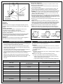
RATCHET
Ratchet Lock
The ratchet lock can be engaged or disengaged, depending upon the
application. Reels are sent from factory with ratchet lock engaged. See
Figure 8.
Operation with Ratchet
The ratchet pawl is spring loaded. It is designed to function in all
acceptable mounting configurations. See Figure 8.
A slight pull on cable will disengage the ratchet. See Figure 8.
Operation without Ratchet
Disengage the ratchet by pivoting the lock-out bar to the lower position.
This will remove the ratchet pawl from the path of the ratchet plate.
Locate the dimple on the lock-out bar in the hole provided.
See Figure 8.
WARNING: Do not engage the ratchet abruptly. Sudden engagement
may cause excessive shock loads to the ratchet pawl.
Push on this end
to rotate lockout
arm to engage or
disengage position.
Push to release
Dimple from hole
latching arm in
engaged position.
Figure 8
Be sure the power is off for all maintenance.
Lubrication
• All springs and bearings are lubricated for life at the factory. Additional
lubrication should not be required.
• Do not apply any lubricants or solvent cleaning agents to slip ring, brush
or insulator surfaces.
Inspections
• Periodically check the reel for any loose or missing fasteners. Tighten or
replace as necessary.
NOTE: Do not over tighten, this will cause fasteners to snap.
• The slip ring assembly should be checked periodically as follows:
– Clean to remove dust and dirt from the slip ring housing area and
all slip ring assembly and brush surfaces.
– Inspect cable for damage or wear which would make it unsafe to use.
MAINTENANCE INSTRUCTIONS
SPRING MOTOR SELECTION CHART
Cable Type
Cable Lengths That Use
This Spring Motor
Spring Motor Part Number (Spring)
14/3 SJEOW-A Up to 50’ G50
12/3 SJOW-A Up to 50’ K50
14/4 SJEOW-A Up to 50’ G50
12/4 SJOW-A Up to 40’ K50
16/3 SOW-A Up to 50’ G50
14/3 SOW-A Up to 40’ K50
12/3 SOW-A Up to 30’ K50
16/4 SOW-A Up to 50’ K50
14/4 SOW-A Up to 35’ K50
12/4 SOW-A Up to 25’ K50
Adding Spring Tension
Viewing from Outer Flange
Rotate Spool while Holding Cable
to Test the Spring Tension
Adding Spring Tension
Viewing from Outer Flange

800-223-4185
1.877.BY.LEGRAND
www.legrand.us
www.legrand.ca
341238 – 09/18
© Copyright 2018 Legrand All Rights Reserved.
© Copyright 2018 Tous droits réservés Legrand.
© Copyright 2018 Legrand Todos los derechos reservados.
TROUBLESHOOTING INSTRUCTIONS
PROBLEM POSSIBLE CAUSE SOLUTION
Reel will not retract cable but has some tension
1) Improper pretension
2) Incorrect reel for application (lift vs. stretch)
3) Cable guide adjustment
1) See Spring Tension Adjustment
2) Verify Application vs. reel selection
3) Check guide alignment
Reel does not have any spring tension 1) Broken spring 1) Verify application and duty cycle
Ratchet will not activate
1) Broken ratchet pawl spring
2) Lock-out option arm deactivated
1) Replace device
2) Activate lock-out arm
Ratchet will not deactivate
1) Over-extension of reel 1) Manually rotate reel spool to deactivate ratchet. Do
not over-extend. (Guide adjustment may prevent
lock-up when over-extended)
Cable wraps improperly (uneven wrapping, wraps
above or jumps flange)
1) Reel mounting not level
2) Cable retraction rate too high
3) Cable guide out of adjustment
1) Mount reel on level surface
2) Maintain steady retraction rate
3) Properly adjust cable guide
Cable twisting or knotting
1) Cable rubbing on or bending around fixed
object
2) Excessive spring tension
3) Inadequate anchoring of cable
1) Check roller guide for function and cable payout path
2) Verify application vs. reel selection. Also check
pretension
3) Adjust anchoring method i.e. and strain relief
Open or intermittent circuit
1) Inadequate connection
2) Loss of brush contact to slip ring
3) Cable defective
1) Check all termination points
2) Check brush wear, spring tension & alignment
3) Perform continuity check on cable termination
points
Circuit trips and/or pitted burned rings or brushes
1) Inadequate amp rating of reel selection 1) Verify application requirements vs. reel & cable
rating
Circuit arcing
1) Amp or voltage above rating of reel
2) Excessive carbon dusk accumulation
3) Water or moisture in slip ring
4) Loss of brush to ring contact
1) Verify application requirements vs. reel & cable
rating
2) Clean dust from inside slip ring
3) Check gasket seal
4) Replace device
-
 1
1
-
 2
2
-
 3
3
-
 4
4


Pass and Seymour 1200_Cable_Reel_IS (PDF) Installation guide
- Type
- Installation guide
Ask a question and I''ll find the answer in the document
Finding information in a document is now easier with AI
Related papers
Other documents
-
Gleason Reel GC and GL Series Cord Reel Installation guide
-
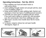 Keeper 05514 Operating instructions
-
 Voxoa K50 User manual
-
 SmartStraps 239 Installation guide
-
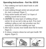 Keeper 03518 Operating instructions
-
Hubbell Wiring Device-Kellems PD1421 Installation guide
-
-
 ATD Tools ATD80010 User manual
-
 ATD Tools The Saber Light ATD-80010 Installation and Operating Instructions
-
JVC MX-K50 Schematic Diagrams


