Page is loading ...

The specifications of this product may vary from this photo and are subject to change without notice.
IRONMAN, IRONMAN TRIATHLON and M-DOT are registered trademarks of World Triathlon Corporation.
This product is licensed by the World Triathlon Corporation.
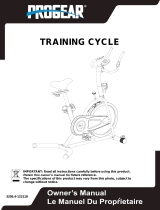
OWNER’S MANUAL
Programmable Upright Bike
6100.4‐061716


SERVICE ----------------------------------------------------------------------- 2
LABEL
PLACEMENT -------------------------------------------------------- 3
PRODUCT SAFETY --------------------------------------------------------- 4
OVERVIEW DRAWING ----------------------------------------------------- 5
HARDWARE AND TOOLS LIST ------------------------------------------ 6
PART LIST ---------------------------------------------------------------------- 7
ASSEMBLY --------------------------------------------------------------------- 8
CONSOLE---------------------------------------------------------------------- 15
ADJUSTMENTS-------------------------------------------------------------- 18
MOVING THE BIKE---------------------------------------------------------- 19
TROUBLESHOOTING & MAINTENANCE ---------------------------- 20
WARRANTY ------------------------------------------------------------------- 22
PART REQUEST FORM --------------------------------------------------- 23
1
TABLEOFCONTENTS

IMPORTANT: FOR NORTH AMERICA ONLY
For damaged, defective products, questions, replacement parts, or any
other service support, please contact our customer service department
(8:00 AM - 5:00 PM Pacific Standard Time, Daily) by the below methods:
For Best Service, please Email:
Service@paradigmhw.com
Response Time: 1-2 Business Days
Website:
www.paradigmhw.com
To
ll-Free:
1-844-641-7922
Response time may vary.
Please have the following information ready when requesting for service:
Your name
Phone number
Model number
Serial number
Part number
Proof of Purchase
For damaged or defective products please contact our customer
service before returning to the store.
Paradigm Health & Wellness, Inc.
1189 Jellick Ave.
City of Industry, CA 91748, USA
2
SERVICE

275
125
125
UNDER PENALTY OF LAW THIS TAG
NOT TO BE REMOVED EXCEPT BYTHE
CONSUMER
NOTICE
This article does not meet
requirements of California
Bureau of Home Furnish-
ings technical bulletin 117.
Care should be exercised
burning cigaretts.
ALL NEW MATERIALCONSISTING
OF POLYURETHANE
FOAM PAD_100%
REGISTRY NO. VA25302 (CN)
manufacturer that the materials
in this article are described in
accordance with law.
Paradigm Health and Wellness, Inc.
1189 Jellick Ave. City of Industry
CA 91748, USA
Paradigm Health and Wellness, Inc.
1189 Jellick Ave. City of Industry, CA
91748 USA
SE SANCIONARÁ LEGALMENTE A
QUIENES QUITEN ESTA ETIQUETA.
SOLO EL CONSUMIDOR PODRÁ
QUITARLA.
MATERIAL COMPLETAMENTE NUEVO
COMPUESTO DE 100% RELLENO DE
ESPUMA DE POLIURETANO.
NOTIFICACIÓN
Este artículo no se ajusta a
Mobiliario boletín técnico
117. Cuidado de California
deben ejercerse cerca de
una llama abierta o con
cigaretts ardientes.
NO. DE REG VA25302 (CN)
materiales de este artículo se
describen según las leyes.
Paradigm Health and Wellness, Inc.
1189 Jellick Ave. City of Industry
CA 91748, USA
SOUS PEINE DE SANCTION LÉGALE,
CETTE ÉTIQUETTE NE PEUT ÊTRE
ENLEVÉE PAR UNE PERSONNE AUTRE
QUE LE CONSOMMATEUR
AVIS
Ce produit ne satisfait pas
-
du devis technique du
California Bureau of Home
Furnishings. Ne pas utiliser
près d’une source de
nue (cigarettes, etc.)
ENTIÈREMENT FABRIQUÉ DE
MATÉRIAUX NEUFS REMBOURRAGE
DE MOUSSE DE
POLYURÉTHANE 100 %
NO D’ENREGISTREMENT
VA25302 (CN)
Cette étiquette est apposée
conformément aux lois Cana-
diennes.
8 am - 5 pm PST
7
9
9
9
3
LABELPLACEMENT

Basic precautions should always be followed when using this equipment. Read all
the instructions before using this equipment which include the following safety
instructions:
1. Read all the instructions in this manual and do warm up exercises before using this
equipment.
2. Before exercising, and in order to avoid injuring yourself, it is recommended that you
perform warm-up exercises for every muscle group.
3. Please make sure that all the components are not damaged and that all the hardware
is thoroughly tighten before use.
4. This equipment should be placed on a flat surface when using. Placing a mat or other
covering material on the ground underneath the equipment is recommended.
5. Please wear proper clothing and shoes when using this equipment; do not wear
clothes that are loose and might get caught by any part of the equipment; remember to
tighten the pedal straps before working out.
6. Do not attempt any maintenance or adjustments other than those described in this
manual. Should any problems arise, discontinue use and consult customer service.
7. Do not use or leave the equipment outdoors.
8. This equipment is for household use only.
9. Only one person should be on the equipment while in use.
10. Keep children and pets away from the equipment while in use. This machine is
designed for adults only. This product requires a minimum of 6 square feet of space for
safe operation.
11. If you feel any chest pains, nausea, dizziness, or shortness of breath, you should stop
exercising immediately and consult your physician before continuing.
12. The maximum weight capacity for this product is 275 lbs/125 kgs.
WARNING: Before beginning any exercise program consult your
physician. This is especially important for people who are over 35 years old or who
have pre-existing health problems. Read all instructions before using any fitness
equipment.
CAUTION: Read all instructions carefully before operating this product.
Retain this Owner’s Manual for future reference.
4
PRODUCTSAFETY

OVERVIEWDRAWING
5

HARDWAREPACK
6

No. Description Q’ty No. Description Q’ty
1 Main Frame 1 20 Hex Bolt M8*15 10
2 Front Post 1 22 Curved Washer φ16*φ8*1.5 2
3 Handlebar 1 23 Lower Console Wire 1
4 Seat Post 1 24 Upper Console Wire 1
5 Front Stabilizer 1 25 Sensor Wire 2
6 Rear Stabilizer 1 26 Philips Screw M5*10 4
8 Left Pedal Strap 1 27 Bottle Holder Screw ST4.8*15 2
10 Right Pedal Strap 1 28 Power Jack 1
11 Console 1 29 Adaptor 1
12 Seat 1 30 Allen Bolt M8*16 2
13 Adjustment Knob M16*1.5 1 34 Front Stabilizer End Cap 2
14 Bottle Holder 1 68 Spring Washer φ20*φ13*2.0 2
15 Carriage Bolt M8*75 4 69 Left Nylon Nut 1/2" 1
16
Big Curved Washer
Ф8*Ф20*2.0
4 70 Right Nylon Nut 1/2" 1
17 Cap Nut M8 4 71 Left Pedal 1
18 Nylon Nut M8 3 72 Right Pedal 1
19 Flat Washer φ16*φ8*δ1.5 11
PARTLIST
7

1. Stabilizers Installation
A. Front Stabilizer: Position the Front Stabilizer (5) in front of the Main Frame (1). Align the
bolt holes and attach the Front Stabilizer (5) onto the front curve of the Main Frame (1) with
two Carriage Bolts (15), two Big Curved Washers (16), two Spring Washers (21), and two
Cap Nuts (17) and tighten with the Multi Hex Tool with Phillips Screwdriver (32) provided.
B. Rear Stabili
zer: Position the Rear Stabilizer (6) behind the Main Frame (1). Align th
e bolt
holes and attach the Rear Stabilizer (6) onto the rear curve of the Main Frame (1) with two
Carriage Bolts (15), two Big Curved Washers (16), two Spring Washers (21), and two Cap
Nuts (17) and Tighten with the Multi Hex Tool with Phillips Screwdriver (32) provided.
ASSEMBLY
8
Hardware:
(15) Carriage Bolt
4PCS
(16) Big Curved Washer
4PCS
(17) Cap Nut
4PCS
(21) Spring Washer
4PCS
Multi Hex Tool with Phillips
Screwdriver
S10, S13, S14, S15 1PC

The Cranks, Pedals, and Pedal Straps are marked “R” for Right and “L” for Left.
2.1 Pedal Strap installation
A. Install the Left Pedal Straps (8) onto the Left Pedal (71), and then install the Right Pedal
Strap (10) on to the Right Pedal (72). The Pedal straps (8,10) are label “L” for Left and “R”
for Right
2.2 Pedals Installation
A. Remove the Left Nylon Nut (69) and Spring Washer (68) and Right Nylon Nut (70) and
Spring Washer (68) from the Left and Right Pedals (71/72) first.
B. Left Pedal Installation: Insert the Left Pedal (71) into the threaded hole in the Left Crank.
Turn the pedal shaft by hand in a
counter-clockwise direction and then tighten using the
Multi Hex Tool with Phillips Screwdriver. Attach the Left Nylon Nut (69) and Spring Washer
(68) onto the Pedal shaft until snug, DO NOT turn the pedal shaft in the clockwise
direction; doing so will strip the threads. Tighten the Left Nylon Nut (69) with the Wrench
provided.
C. Right Pedal Installation: Insert the Right Pedal (72) into the threaded hole in the Right
Crank. Turn the pedal shaft by hand in a clockwise direction and tighten using the Multi
Hex Tool with Phillips Screwdriver. Attach the Right Nylon Nut (70) and Spring Washer (68)
onto the Pedal shaft until snug, DO NOT turn the pedal shaft in the clockwise direction;
doing so will strip the threads. Tighten the Right Nylon Nut (70) with the Wrench provided.
ASSEMBLY
9
Important:
Make sure the RIGHT pedal matches
up with the RIGHT crank and the LEFT
pedal matches up with the LEFT
crank. If reversed the cranks may
become damaged or stripped.
Wrench 1PC
Multi Hex Tool with Phillips
Screwdriver
S10, S13, S14, S15 1PC

3. Seat Post and Seat Installation
A. Seat Installation: Remove the 3 Nylon Nuts (18) and 3 Flat Washers (19) from the
Seat (12). Attach the Seat (12) onto the seat bracket of the Seat Post (4), with 3 Nylon
Nuts (18), and 3 Flat Washers (19). Then tighten the Nylon Nuts (18) with the Multi Hex
Tool with Phillips Screwdriver (32) provided.
B. Seat Post Installation: Loosely insert the Adjustment Knob (13) by turning it clockwise.
Pull on the Adjustment Knob (13) to clear space to insert the Seat Post (4) into the tube of
the Main Frame (1). Lock the Seat Post (4) in place by releasing the Adjustment Knob (13)
and sliding the Seat Post (4) up or down slightly until the Adjustment Knob (13) "pops" into
the locked position. Then securely tighten the Adjustment Knob (13) by twisting it in a
clockwise direction until tight.
ASSEMBLY
10
Multi Hex Tool with Phillips
Screwdriver
S10, S13, S14, S15 1PC

`
4. Front Post Installation
Remove six Hex Bolts (20), six Spring Washers (21), two Curved Washers (22), and
four Flat Washers (19) from the Main Frame (1). Connect the Lower Console Wire (23)
from the Main Frame (1) and Upper Console Wire (24) from the Front Post (2), as
shown in Fig. AA-1. Slide the Front Post (2) down onto the Main Frame (1), being
careful to not pinch or damage the wires. On the sides of the Front Post (2) install four
Hex Bolts (20), four Spring Washers, and four Flat Washers by hand. Then install two
Hex Bolts (20), two Spring Washers (21), and two Curved Washers (22) into the front
and Back side of the Front Post (2) by hand. Once all the hardware has been installed
tighten the Hex Bolts (20) with the 6mm Allen Wrench (31) provided.
11
ASSEMBLY
6mm Allen Wrench
1PC

5. Handlebar Installation
Remove four Hex Bolts (20), four Spring Washers (21) and four Flat Washers (19)
from the sides of the Front Post (2). Feed the Sensor Wires (25) into the hole on
the Front Post (2) as shown in Fig. AA-2. Pull the sensor Wires (25) out from the
large hole at the top of the Front Post (2) and leave them hanging outside of the
Front Post (2) for the moment. Attach the Handlebar (3) onto the Front Post (2)
with four Hex Bolts (20), four Spring Washers (21) and four Flat Washers (19).
Tighten the Hex Bolts (20) with the 6 mm Allen Wrench (31) provided.
ASSEMBLY
6mm Allen Wrench
1PC
12

6. Console Installation
Remove the four Phillip Screws (26) from the backside of the Console (11).
Connect the Upper Console Wire (24) and Sensor Wires (25) to the wires at the back
of the Console (11), as shown in Fig. AA-3. Gently insert the computer wires into the
Front Post (2) and be sure the wires aren’t pinched or disconnected. Attach the
Console (11) onto the Front Post (2) with the four Phillip Screws (26) previously
removed. Then tighten the Phillip Screws (26) with the Multi Hex Tool with Phillips
Screwdriver (32) provided.
7. Bottle Holder Installation
Remove two Bottle Holder Screws (27) from the Front Post (2). Attach the
Bottle Holder (14) onto the Front Post (2) with the two Bottle Holder Screws (27)
and tighten with the Multi Hex Tool with Phillips Screwdriver (32) provided.
ASSEMBLY
13
Multi Hex Tool with Phillips
Screwdriver
S10, S13, S14, S15 1PC
Multi Hex Tool with Phillips
Screwdriver
S10, S13, S14, S15 1PC

8. Adaptor Installation
Plug the small end of the Adaptor (29) into the Power Jack (28) located at the rear of the
Main Frame (1), as shown in Fig. AA-4. Before plugging in, make sure to carefully check the
specifications on the Adaptor. Plug the Large end of the Adaptor (29) into the electrical
outlet.
ASSEMBLY
14

Con
s
START/
S
1. Star
t
2. Hol
d
con
s
DOWN
B
1. Pre
s
par
a
2. Pre
s
UP BUT
T
1. Pre
s
CA
L
2. Pre
s
ENTER
B
1. Pre
s
wor
k
RECOV
E
1. Pre
s
a.
MODE B
U
1. Pre
s
Cal
o
s
ole B
u
S
TOP BU
T
t
s and Pa
u
d
ing the b
u
s
ole for a
n
B
UTTON:
s
s to decr
e
a
meter: TI
M
s
sing durin
g
T
ON:
s
s to Incre
a
L
ORIES.
s
sing durin
B
UTTON:
s
s to selec
t
k
out.
E
RY BUT
T
s
s to enter
The Reco
v
poor fitne
s
U
TTON:
s
s to switc
h
o
ries durin
g
u
tton
s
T
TON:
u
ses a wo
r
u
tton for 3
s
n
ew worko
e
ase the v
a
M
E, DIST
A
g
a worko
u
a
se the va
g a worko
u
t
the Goal
T
ON:
into Reco
v
v
ery Scale
s
s.
h
displaye
d
g
workout.
s
:
r
kout.
s
econds
w
u
t.
a
lue of the
A
NCE, CA
L
u
t will dec
r
l
ue of the
s
u
t will incr
e
option (TI
M
v
ery functi
o
is a rang
e
d
workout
v
w
ill reset th
e
selected
w
L
ORIES.
r
ease the
r
s
elected
w
e
ase the r
e
M
E, DIST
A
o
n when
C
e
of F1 – F
6
values R
P
CONS
O
15
e
w
orkout
esistance
w
orkout pa
r
e
sistance l
A
NCE, CA
L
C
onsole ha
6
, F1 signi
P
M to SPE
E
O
LE
load.
r
ameter: T
I
oad.
L
ORIES)
p
s
the hear
t
fies great
f
E
D, ODO
t
IME, DIS
TA
p
rior to sta
r
r
t rate valu
e
f
itness, an
t
o DIST, a
n
TA
NCE,
r
ting a
e
.
d F6 signi
f
n
d WATT t
o
f
ies
o

PRO
G
Profil
e
Th
e
challen
Ho
w
is turned
profiles
b
button o
n
pressing
Th
e
DISTA
N
Ho
w
console i
s
program
one of th
e
To choos
change i
s
which th
e
button to
stop the
w
Note: M
u
console
Goals y
o
Progr
a
G
RA
M
e
Progr
a
e
consol
e
ge you
a
w
to quick
on is prog
b
y using th
e
n
ce you ha
the UP or
e
consol
e
N
CE, an
d
w
to set a
W
s
turned o
n
profiles b
y
e
work pa
r
e among t
s
flashing.
e
console
w
initiate yo
u
w
orkout.
u
ltiple Wo
will stop
y
o
u have s
e
a
m Pro
f
M
S:
a
m:
e
has 21
a
nd mee
t
start a Pr
o
ram profil
e
e
UP or D
O
ve select
e
DOWN ar
r
e
can be
d
CALO
R
W
orkout
G
n
is progr
a
y
using the
r
ameters t
o
he param
e
When the
w
ill count
d
u
r workou
t
rkout Go
a
y
our wor
k
e
t, press t
f
iles:
Preset
P
t
your fi
t
o
gram Pr
o
e
P1. Fro
m
O
WN butt
o
d the desi
r
r
ow butto
n
set to c
o
R
IES.
G
oal Prog
r
a
m profile
P
UP or DO
o
flash, th
o
e
ters pres
s
paramete
r
d
own by u
s
t
. When a
g
a
ls can be
k
out. To c
o
he STAR
T
C
P
rogram
t
ness go
o
file: The
f
m
this scre
e
o
ns. To sta
r
ed progr
a
n
s.
o
unt do
w
r
am Profil
P
1. From t
O
WN butto
n
o
se param
e
s
the ENT
E
r
you wan
t
s
ing the U
P
g
oal is ac
h
set. Whe
n
o
ntinue y
o
T
button t
w
C
ONSO
L
16
options
als. See
f
irst scree
n
e
n you ca
n
rt an imm
e
a
m profile.
w
n a Wo
r
e: The fir
s
his screen
n
s. Pressi
n
e
ters are:
T
E
R button
u
t
is flashin
g
P
or DOW
N
h
ieved the
n
one of t
o
ur work
o
w
ice in or
d
L
E
to choo
s
the dia
g
n
that app
e
n
select an
y
e
diate wor
k
C
ontrol th
e
r
kout G
o
t screen t
h
you can
s
n
g the EN
T
T
IME, DIS
T
u
ntil the p
a
g
, you can
N
buttons.
console w
h
e param
e
ut and re
a
d
er to res
u
se from
g
ram bel
o
e
ars when
y
of the ot
h
k
out press
e
resistan
c
o
al base
d
h
at appear
s
elect any
o
T
ER butto
n
TANCE, o
a
rameter
y
assign a
v
Press the
w
ill sound
a
e
ter reac
h
a
ch the o
t
ume.
to help
o
w.
the cons
o
h
er progra
the STAR
c
e level by
d
on TIM
s
when th
e
o
f the oth
e
n
will caus
e
r
CALORI
E
y
ou wish t
o
v
alue from
START
a
n alarm a
n
h
es zero t
h
her Work
o
o
le
m
T
E,
e
e
r
e
E
S.
o
n
d
h
e
o
ut

Recov
The
after a w
o
Your rec
o
heart rat
e
Ho
w
heartrate
decreas
e
Ho
w
rate sen
s
displaye
d
rate, and
sensors
f
display y
o
end of th
e
The fitn
e
F1 – exc
e
F2 – goo
d
F3 – sati
s
F4 – min
i
F5 – fitn
e
F6 – fitn
e
6
Note: T
h
informa
t
ery Pr
o
Recovery
o
rkout. Th
e
o
very ratin
g
e
at the en
w
it works:
after 60 s
e
faster an
d
w
to activa
t
s
ors so the
d
on the s
c
the time r
e
f
or the enti
o
ur score.
e
test) will
e
ss ranki
n
e
llent fitne
s
d
fitness
s
factory fit
n
i
mal fitnes
s
e
ss needs
e
ss needs
6
0 second
h
ese rank
i
t
ion cons
u
o
gram:
Program
g
e
recover
y
g
is calcul
a
d of a wor
k
The large
econds, t
h
d
be score
t
e Recov
e
console
d
c
reen, alon
e
maining
f
re duratio
n
The two h
continue t
n
g
s
s
n
ess
s
improvem
e
major imp
r
countdo
w
i
ng are fo
r
u
lt with y
o
g
ives you f
e
rating is
a
a
ted by ev
a
k
out and y
r the diffe
r
h
e bette
r
y
o
d closer t
o
e
ry Progr
a
d
etects a p
g with you
f
or the test
n
. Once th
e
eart rate v
o be displ
a
e
nt
r
ovement
C
Hig
h
the
w
n
r
very ba
s
o
ur perso
n
f
eedback
a
a
value wit
h
a
luating h
o
y
our heart
r
r
ence bet
w
o
ur recov
e
o
F1.
a
m:
A
fter
y
ulse. Pus
h
u
r highest
h
t
. The test
w
e
test is c
o
v
alues (yo
u
a
yed on th
C
ONSO
L
h
est heart
test
s
ic fitness
n
al care
p
17
a
bout the r
a
h
which y
o
o
w large t
h
r
ate after
6
w
een your
p
ry rating.
A
y
our worko
h
the REC
O
h
eart rate
d
w
ill last 6
0
o
mplete, t
h
u
r highest
h
e lower ri
g
S
c
L
E
rate durin
g
tracking,
p
hysician.
a
te at whi
c
o
u
r
person
a
h
e differen
c
6
0 second
s
p
eak heart
A
fit perso
n
ut stop pe
d
O
VERY bu
d
uring the
0
seconds,
h
e console
h
eart rate
a
g
ht corner.
c
ore scree
g
C
u
for more
c
h you he
a
a
l fitness
c
c
e is betw
e
s
of restin
g
t
rate and
y
n
’s heart r
a
d
aling and
u
tton. A lar
g
test, your
hold the
h
will beep
3
a
nd your h
e
n: F1.0
u
rrent hea
r
accurate
a
rt recover
s
c
an be jud
g
e
en your
p
g
.
y
our restin
g
a
te will
hold the
h
g
e heart w
c
urrent he
h
eart rate
3
times, a
n
eart rate
a
r
t rate
health
s
g
ed.
p
eak
g
h
eart
ill be
art
n
d
a
t the

Seat Post Adjustment
Loosen Adjustment Knob (13) by first twisting counter clockwise. When loosen, the
Adjustment Knob (13) can be pull out slightly to release the Seat Post (4), allowing it to slide up
and down. Release the Adjustment Knob (13) at the desired height, allowing it to pop into one of
the nearest available holes. Shift the Seat Post (4) up and down slightly to make sure it has
“popped” into a hole. Tighten the Adjustment Knob (13) by turning it
clockwise in order to
secure Seat Post (4) height.
Floor Level Adjustment
Turn the dials in the Rear Stabilizer End Caps (45) at both sides of the Rear
Stabilizer (6) to level the bike with the floor. It is very important that all Front /Rear
Stabilizer End Caps (34) & (45) on the front and rear stabilizer make contact with
the floor.
18
ADJUSTMENTS
/
