Page is loading ...

5/16"
6 PLCS
1 3/4" 1 3/4"
5 1/8"
1 5/32"
13/32"
2 1/2"
1 5/32"
15/16"
1/16"
8 PLCS
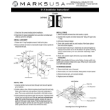
HK01-I Template and installation instructions
Warning: Verify door profile prior to installation
You will require a profile wide enough for proper installation.
With the door closed, the minimum inside door profile width is 1-7/8” from the edge of the door frame (glass side) to
the edge of the door jamb or metal door frame (z-bar), which ever is narrower.
The minimum outside door profile width is 2” from the edge of the door frame (glass side) to
the edge of the door jamb or metal door frame Z-bar), which ever is narrower.
Drilling template prerequisite: Determine if your storm door is right or left handed
From outside of the door, looking in, if the hinges are on your left, your door is left handed. Your door will open to the left side.
If the hinges are on your right, your door is right handed. Your door will open to the right side.
Ensure that the inside latch paddle does not interfere with the prime door lock.
cutting linecutting line
RFQHKE
PAGE 1 OF 4

A
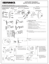
Template Placement and Drilling Instructions
1. Fold the template on the dotted line to 90
according to the handedness (left or right).
2. With the door in closed position,
place folded template on the inside of the door
so that the SIDE A is against the jamb
or metal z-bar, which ever projects out furthest;
and SIDE B is on the inside surface of the door.
3. Use a center punch to mark the position
of 6 holes on the inside surface of the door on SIDE B.
Mark the position of 4 holes on the jamb on SIDE A (for strikes).
4. Using a 5/16” drill bit, drill 6 holes straight through
door on SIDE B.
5. Using a 1/16"drill bit, drill 4 pilot holes to a depth of 1"
on the jamb on SIDE A.
JAMB
DOOR
DETAIL A
PAGE 2 OF 4

DOOR THICKNESS
1"
1 1/4"
1 1/2"
1 3/4"
2"
2 1/8"
1. Print out this sheet using 1:1 scale.
2. Over lay handle spindle on top of the image.
3. Select the spindle that matches your door thickness.
The handle spindle has now been selected and is ready for installation.
HANDLE SPINDLE SELECTION
ALIGN CAP OF SPINDLE HERE
ALIGN CAP OF SPINDLE HERE
RULER FOR
DOOR THICKNESS
KEY LOCK SPINDLE PREPARATION
1. Print this sheet using 1:1 scale.
2. Over lay flat spindle against the image.
3. Mark door thickness on the spindle.
4. Cut off the portion of the spindle beyond the mark line.
The key lock flat spindle is now ready for installation.
PLACE SPINDLE HERE
LATCH SCREW SELECTION
DOOR THICKNESS
1"~1 1/4"
1 1/2"
1 3/4"
2"
2 1/8"
1. Print out this sheet using 1:1 scale.
2. Over lay screws on top of the image.
3. Select the screws that matche your door thickness.
The latch screws have now been selected and are ready for installation.
DEADBOLT SCREW SELECTION
DOOR THICKNESS
1"
1 1/4"
1 1/2"~1 3/4"
2"~2 1/8"
1. Print out this sheet using 1:1 scale.
2. Over lay screws on top of the image.
3. Select the screws that matche your door thickness.
The deadbolt screws have now been selected and are ready for installation.
PAGE 3 OF 4
SPINDLES AND SCREWS SELECTION

max 1/2"
min 1/4"
Deadbolt Spindle Projected Length
KEY LOCK
DEADBOLT
DEADBOLT
STRIKE
HANDLE
LATCH
HANDLE
SPINDLE
DEADBOLT
SPINDLE
LATCH
STRIKE
LATCH
STRIKE
SPACER
JAMB
DOOR
max 3/8"
min 1/4"
Handle Spindle Projected Length
Handle & Latch Installation
1. Rotate the outside handle to the left or right
according to your door handedness.
2. Insert the pre-selected handle spindle (see page 3)
into the center hole of the outside handle from the back side of
the handle housing; ensure the spindle is fully sitted into the hole.
The spindle locks the handle in place.
3. Place the outside handle assembly on the door.
(If your door thickness is not standard then:
The spindle should project through inside
of the door a max of 3/8" and a min of 1/4".
You may have to shorten the spindle.)
4. Place the latch on the inside of the door, fasten with
two machine screws pre-selected (see page 3).
Do not over tighten screws.
5. Place the latch strike and the thick spacer against the jamb
(the spacer shall be placed in between the strike and the jamb),
align with pilot holes on jamb and fasten with two tapping screws.
Key Lock & Deadbolt Installation
1. Place the key lock on the outside of the door
and hold it in place temporally by hand.
2. Insert the pre-prepared flat spindle (see page 3)
from the inside through the center hole into the keylock;
ensure the spindle is fully inserted.
(If your door thickness is not standard then:
The spindle should project through
inside of door a max of 1/2" and min of 1/4".
Cut off the excessed portion of the spindle.)
3. Place the deadbolt on inside of the door,
align the center hole carefully with the spindle,
fasten with two machine screws pre-selected (see page 3).
Do not over tighen screws.
4. Place the strike for the deadbolt on jamb,
align with pilot holes on jamb, fasten with two tapping screws.
Thank you for your purchase.
If you require any information or installation assistance,
please contact our customer service.
Monday to Friday 7:30 am -3 pm (Eastern Time)
Tel: 1-800-361-2236 x 230
e-mail:
Updated instructions (if applicable) can be found at
www.idealinc.com
IDEAL SECURITY INC.
LASALLE, QUEBEC, CANADA
CORAOPOLIS, PA., USA
PAGE 4 OF 4

1.142 in
29 mm
1.312 in
33.3 mm
2.125 in
54 mm
1.926 in
49 mm
HK01-I DIMENSIONS
2.725 in
69.2 mm
1.250 in
31.8 mm
2.500 in
63.5 mm
29 mm
1.138 in
1.750 in
44.5 mm
1.750 in
44.5 mm
.877 in
22.3 mm
1.655 in
42 mm
4.455 in
113 mm
3.878 in
98.5 mm
2.760 in
70 mm
1.641 in
41 mm
.500 in
12.7 mm
.359 in
9.1 mm
/