En-2
1. SAFETY PRECAUTIONS
• Be sure to read this manual thoroughly before installation.
• The warnings and precautions indicated in this manual contain important information
pertaining to your safety. Be sure to observe them.
• Hand this manual, together with the operating manual, to the customer. Request the
customer to keep them on hand for future use, such as for relocating or repairing the unit.
WARNING
Indicates a potentially or imminently hazardous situation which,
if not avoided, could result in death or serious injury.
Installation of this product must be done by experienced service technicians or profes-
sional installers only in accordance with this manual. Installation by nonprofessional or
improper installation of the product may cause serious accidents such as injury, water
leakage, electric shock, or fi re. If the product is installed in disregard of the instructions
in this manual, it will void the manufacturer’s warranty.
Do not turn on the power until all work has been completed. Turning on the power before
the work is completed can cause serious accidents such as electric shock or fi re.
To avoid getting an electric shock, never touch the electrical components soon after the
power supply has been turned off. After turning off the power, always wait
10 minutes or more before you touch the electrical components.
If refrigerant leaks when you are working, ventilate the area. If the leaking refrigerant is
exposed to a direct fl ame it may produce a toxic gas.
Do not use this equipment with air or any other unspecifi ed refrigerant in the refrigerant
lines. Excess pressure can cause a rupture.
Installation must be performed in accordance with regulations, codes, or standards for
electrical wiring and equipment in each country, region, or the installation place.
This appliance is not intended for use by persons (including children) with reduced
physical, sensory or mental capabilities, or lack of experience and knowledge, unless
they have been given supervision or instruction concerning use of the appliance by a
person responsible for their safety. Children should be supervised to ensure that they do
not play with the appliance.
To avoid danger of suffocation, keep the plastic bag or thin fi lm used as the packaging
material away from young children.
CAUTION
Indicates a potentially hazardous situation that may result in
minor or moderate injury or damage to property.
Read carefully all safety information written in this manual before you install or use the
air conditioner.
Install the product by following local codes and regulations in force at the place of instal-
lation, and the instructions provided by the manufacturer.
This unit must be installed by qualifi ed personnel with a capacity certifi cate for handling
refrigerant fl uids. Refer to regulation and laws in use on installation place.
This product is part of a set constituting an air conditioner. The product must not be
installed alone or be installed with non-authorized device by the manufacturer.
Always use a separate power supply line protected by a circuit breaker operating on all
wires with a distance between contact of 3 mm for this product.
To protect the persons, earth (ground) the product correctly, and use the power cable
combined with an Earth Leakage Circuit Breaker (ELCB).
The product is not explosion proof, and therefore should not be installed in explosive
atmosphere.
Do not touch the fi ns of the heat exchanger. Touching the heat exchanger fi ns could
result in damage to the fi ns or personal injury such as skin rupture.
This product contains no user-serviceable parts. Always consult experienced service
technicians for repairing.
When moving or relocating the air conditioner, consult experienced service technicians
for disconnection and reinstallation of the product.
Do not place any other electrical products or household belongings under the product.
Condensation dripping from the product might get them wet, and may cause damage or
malfunction of the property.
2. ABOUT THIS PRODUCT
2.1. Precautions for using R410A refrigerant
WARNING
Do not introduce any substance other than the prescribed refrigerant into the refrigera-
tion cycle. If air enters the refrigeration cycle, the pressure in the refrigeration cycle will
become abnormally high and cause the piping to rupture.
If there is a refrigerant leak, make sure that it does not exceed the concentration limit.
If a refrigerant leak exceeds the concentration limit, it can lead to accidents such as
oxygen starvation.
Do not touch refrigerant that has leaked from the refrigerant pipe connections or other
area. Touching the refrigerant directly can cause frostbite.
If a refrigerant leak occurs during operation, immediately vacate the premises and thor-
oughly ventilate the area. If the refrigerant comes in contact with a fl ame, it produces a
toxic gas.
2.2. Special tool for R410A
WARNING
To install a unit that uses R410A refrigerant, use dedicated tools and piping materi-
als that have been manufactured specifi cally for R410A use. Because the pressure of
R410A refrigerant is approximately 1.6 times higher than the R22, failure to use dedi-
cated piping material or improper installation can cause rupture or injury. Furthermore, it
can cause serious accidents such as water leakage, electric shock, or fi re.
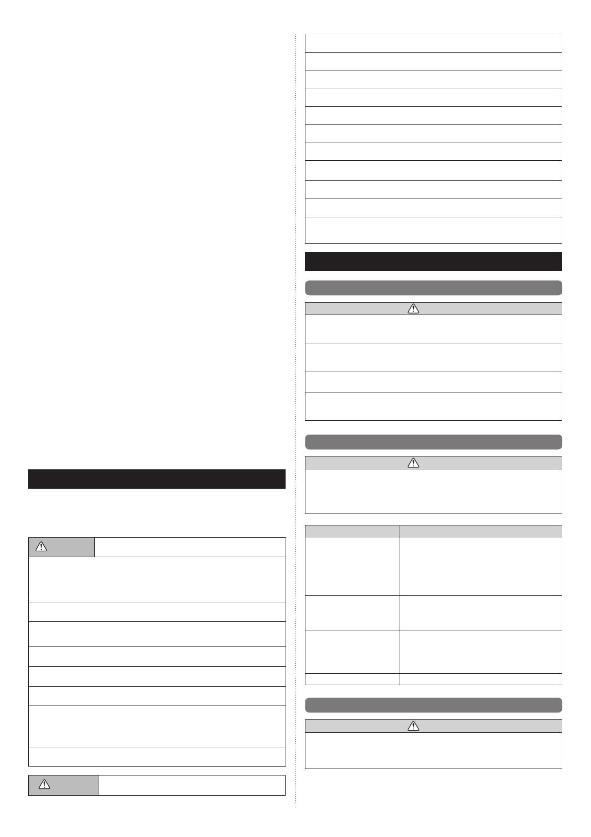
Tool name Changes
Gauge manifold
The pressure in the refrigerant system is extremely
high and cannot be measured with a conventional
gauge. To prevent erroneous mixing of other refriger-
ants, the diameter of each port has been changed. It
is recommended to use a gauge manifold with a high
pressure display range of –0.1 to 5.3 MPa and a low
pressure display range of –0.1 to 3.8 MPa.
Charging hose
To increase pressure resistance, the hose material
and base size were changed.
(The charging port thread diameter for R410A is
1/2-20 UNF.)
Vacuum pump
A conventional vacuum pump can be used by install-
ing a vacuum pump adapter.
Be sure that the pump oil does not back fl ow into
the system. Use one capable for vacuum suction of
–100.7 kPa (5 Torr, –755 mmHg).
Gas leakage detector
Special gas leakage detector for R410A refrigerant.
2.3. Accessories
WARNING
For installation purposes, be sure to use the parts supplied by the manufacturer or other
prescribed parts.
The use of non-prescribed parts can cause serious accidents such as the unit to fall,
water leakage, electric shock, or fi re.
• The following installation parts are furnished. Use them as required.
• Keep the Installation Manual in a safe place and do not discard any other accessories
until the installation work has been completed.
INSTALLATION MANUAL
PART No. 9378590069-04
INDOOR UNIT (Cassette type)
Contents
1. SAFETY PRECAUTIONS .........................................................................................2
2. ABOUT THIS PRODUCT ..........................................................................................2
2.1. Precautions for using R410A refrigerant ...........................................................2
2.2. Special tool for R410A ...................................................................................... 2
2.3. Accessories .......................................................................................................2
2.4. Optional parts....................................................................................................3
3. INSTALLATION WORK .............................................................................................3
3.1. Selecting an installation location ....................................................................... 3
3.2. Installation dimension ....................................................................................... 3
3.3. Installation the unit ............................................................................................4
4. PIPE INSTALLATION ................................................................................................5
4.1. Selecting the pipe material................................................................................5
4.2. Pipe requirement...............................................................................................5
4.3. Flare connection (pipe connection) ................................................................... 5
4.4. Installing heat insulation....................................................................................6
5. INSTALLING DRAIN PIPES .....................................................................................6
6. ELECTRICAL WIRING ..............................................................................................7
6.1. Wiring system diagram ..................................................................................... 7
6.2. Connection cable preparation ...........................................................................8
6.3. Connection of wiring ......................................................................................... 8
7. REMOTE CONTROLLER SETTING ........................................................................8
7.1. Installing the remote controller .......................................................................... 8
7.2. Setting the dip switches ....................................................................................9
8. CASSETTE GRILLE INSTALLATION .......................................................................9
9. FUNCTION SETTING ............................................................................................... 9
9.1. Turning on the power ........................................................................................ 9
9.2. Function setting...............................................................................................10
10. SPECIAL INSTALLATION METHODS ....................................................................12
10.1. Group control system .................................................................................... 12
10.2. Dual remote controllers ................................................................................. 12
11. TEST RUN ..............................................................................................................12
12. CHECK LIST ...........................................................................................................13
13. OPTIONAL KIT INSTALLATION (OPTION) ............................................................ 13
14. CUSTOMER GUIDANCE ....................................................................................... 13
15. ERROR CODES .....................................................................................................13
[Original instructions]