Page is loading ...

SAFETY OPERATION MANUAL INSTRUCTIONS
FORM 50073344
REVISION H COMPRESSION CABLE PULLING GRIPS
Safety And Work Load Factors
Compression pulling grips are single use for pulling electrical cable. They are easy and fast
to install, providing the user with a slim prole that allows for easy passage through ducts
and conduit.
Compression Pulling Grips
Single-use compression cable pull product line is designed with the following Features & Benets:
BURNDY®
1. Pulling grips are to be installed by a qualied individual in accordance with all
applicable national and local safety, electrical and rigging codes, as well as per the
BURNDY® installation requirements.
2. Ensure that the correct grip is selected for your specic needs.
3. DO NOT use a pulling grip for any application other than pulling cable.
4. Thoroughly examine the grip for damage. DO NOT use a damaged grip.
5. Ensure that the recommended work load of the grip is suitable for the application.
Never use grips at their approximate rated breaking strength.
6. DO NOT alter grips in any way.
7. DO NOT attach any type of pulling hardware to any point on the grip other than the pulling
eye. The pulling eye is the only acceptable means of attachment to external hardware.
1. Range Taking With Dieless Tools
2. Accommodates (See table for specic wire combinations).
3. Parallel - Each compression grip comes in various lanyard length sizes
for pulling multiple cables simultaneously.
4. Crimp Bands - Crimp marks for easy crimp locations.
Installation Instruction Support
Scan QR Code for installation videos and sales documentation.
The broad application of compression grips on a variety of cable requires that adequate safety
factors be used to establish working loads. The approximate breaking strength of a
COMPRESSION grip represents an average calculation based on data established from
actual direct tension testing done in our engineering laboratories, see table below for
maximum rated pulling load.
It is impossible to catalog or guarantee a safety factor suitable for all applications as operating
conditions are never the same. The tension, diameter, movement, number of objects gripped,
gripping surface, and the attachments used are just some of the factors which vary with each
application. These factors, together with the eects of abrasion, corrosion, or abuse and any
other variables of a specic application, must be considered by the user and grip replaced as
appropriate. Where the conditions of the application are not well dened or known, or where
risk of injury to person or property is involved, a greater safety factor should be utilized.
Any warranty as to quality, performance or tness for the use of grips is always premised on
the condition that the published breaking strengths apply only to new, unused grips, and that
such products are properly stored, handled, used, maintained and inspected by the user for
the use and condition of the grip.
It is very important to comply with all the following precautions. Failure to do
so may result in property damage, personal injury or death.
Caution
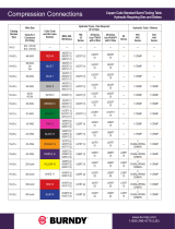
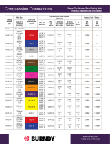
Catalog
Number Wire Size
Copper
(Concentric
Compress
Compact) Wire
Aluminum
(Concentric
Compress
Compact) Wire
Dieless tools Y/
PAT644
(# Crimps)
Copper
(Concentric
Compress)
Wire ONLY
Copper
(Compact)
Wire ONLY
Aluminum
(Concentric
Compress
Compact) Wire
Y / PAT750 Y /
PAT46
(# Crimps)
Min Wire Strip
Length
YCP4CL-
#8 AWG 130 130
Y / PAT644 (1) Y /
PAT444S (1) NA NA NA NA 1.38”#6 AWG 210 210
#4 AWG 300 300
YCP25L-
#4 AWG 300 300 Y / PAT644 (1)
NA NA NA NA
2.50”
#3 AWG 400 400 Y / PAT644 (1) 2.50”
#2 AWG 500 400 Y / PAT644 (1) 2.50”
#1 AWG 1,200 400 Y / PAT644 (1) 2.50”
1/0 AWG 1,200 400 Y / PAT644 (1) 1,200 550 400 U25RT (1) 2.50”
YCP28L-
2/0 AWG 1,200 400 Y / PAT644 (2)
NA NA NA NA
3.00”
3/0 AWG 2,000 750 Y / PAT644 (2) 3.00”
4/0 AWG 2,000 1,000 Y / PAT644 (2) 2,000 1,000 1,000 U28RT (2) 3.00”
YCP31L-
250 KCMIL 2,000 1,200 Y / PAT644 (3)
NA NA NA NA
3.25”
300 KCMIL 4,000 1,500 Y / PAT644 (3) 3.25”
350 KCMIL 4,000 1,800 Y / PAT644 (3) 4,000 1,400 1,800 U31RT (3) 3.25”
YCP34L-
400 KCMIL 4,000 2,000 Y / PAT644 (3)
NA NA NA NA
3.25”
450 KCMIL 5,000 2,400 Y / PAT644 (3) 3.25”
500 KCMIL 5,000 2,700 Y / PAT644 (3) 5,000 2,200 2,700 U34RT (3) 3.25”
YCP39L-
550 KCMIL 5,000 3,600 Y / PAT644 (3)
NA NA NA NA
3.25”
600 KCMIL 5,000 3,600 Y / PAT644 (3) 3.25”
650 KCMIL 5,000 3,600 Y / PAT644 (3) 3.25”
700 KCMIL 5,000 3,600 Y / PAT644 (3) 3.25”
750 KCMIL 5,000 3,600 Y / PAT644 (3) 5,000 2,200 3,600 U39RT (3) 3.25”
YCP44L-
900 KCMIL 5,000 3,600 Y / PAT644 (3) NA NA NA NA 3.25”
1,000 KCMIL 5,000 5,000 Y / PAT644 (3) 5,000 2,200 5,000 U44XRT (3) 3.25”

1. Select the appropriate compression cable pull for the wire being pulled. Be sure to inspect
the compression cable pulls prior to use, to ensure no visual damage. BURNDY® does not
permit the use of damaged compression cable pulls.
2. Measure the insulated wire to determine strip length or use the table to determine the
appropriate insulation strip length of the wire. End of insulated wire should be lined up with
the “DO NOT CRIMP BEYOND” line on the barrel, which is the line closest to the lanyard.
3. Carefully remove the required amount of insulation. If wire is not stripped per the minimum
requirement and or the bare wire is damaged from stripping, BURNDY® does not permit the
use of the compression cable pullers. The maximum rated pull loads dened in the tables are
based on properly stripping the wire insulation and having no damaged wire strands.
4. Insert the wire fully into the appropriate compression cable pull barrel.
5. Installation Tooling Requirement:
6. Once all the crimps have been properly applied, the compression grips are ready for use.
SAFETY OPERATION MANUAL INSTRUCTIONS
FORM 50073344
REVISION H COMPRESSION CABLE PULLING GRIPS
Installation Steps
• Wire that is not stripped to the appropriate length may result in the bare wire not fully
inserting into the compression barrel sleeve and therefore having an inadequate
installation. BURNDY® does not permit the use of their cable pulls when wire is not fully
inserted, as this can result in a failure of the compression cable pulls.
• Wire that is damaged during the wire stripping process may result in an inadequate
compression of the sleeve. BURNDY® does not permit the use of their cable pulls if the
wire is damaged, as this can result in a failure of the compression cable pulls.
• Required to rotate each consecutive crimp 180 degrees.
• Required to start your crimps from the knurl band closest to the lanyard, with each-
consecutive crimp toward the wire.
• With the use of a 444S or 644 series die-less installation tools, apply the proper number of
crimps to the barrel centered on the knurl bands. See table for the required number of
crimps per cable pull. If a barrel requires more than 1 crimp
• With the use of a PAT750-, Y750-, PAT46-, or Y46- installation tools, apply the proper
number of crimps to the barrel centered on the knurl bands. See table for proper number of
crimps. Crimps DO NOT have to be rotated with U-dies.
/

