Page is loading ...

Heat & Glo • PIER-HVB-IPI, ST-HVB-IPI • 2006-901 Rev. C • 12/07 1
Models:
Pier-HVB-IPI
ST-HVB-IPI
Owner’s Manual
Installation and Operation
• Do not store or use gasoline or other flamma-
ble vapors and liquids in the vicinity of this or
any other appliance.
• What to do if you smell gas
- Do not try to light any appliance
- Do not touch any electrical switch. Do not
use any phone in your building.
- Immediately call your gas supplier from a
neighbor’s phone. Follow the gas supplier’s
instructions.
- If you cannot reach your gas supplier, call
the fire department.
• Installation and service must be performed by
a qualified installer, service agency, or the gas
supplier.
WARNING: If the information in these
instructions is not followed exactly, a fire
or explosion may result causing proper-
ty damage, personal injury, or death.
HOT SURFACES!
Glass and other surfaces are hot during
operation AND cool down.
Hot glass will cause burns.
•DO NOT touch glass until it is cooled
• NEVER allow children to touch glass
• Keep children away
WARNING
• CAREFULLY SUPERVISE children in same room as fireplace.
• Alert children and adults to hazards of high temperatures.
High temperatures may ignite clothing or other flammable
materials.
• Keep clothing, furniture, draperies and other flammable
materials away.
DO NOT DISCARD THIS MANUAL
CAUTION
Important operating
and maintenance
instructions included.
This appliance may be installed as an OEM installation in
manufactured home (USA only) or mobile home and must
be installed in accordance with the manufacturer’s instruc-
tions and the manufactured home construction and safety
standard, Title 24 CFR, Part 3280 or Standard for Installa-
tion in Mobile Homes, CAN/CSA Z240MH.
This appliance is only for use with the type(s) of gas indi-
cated on the rating plate.
Installation and service of this appliance should be
performed by qualified personnel. Hearth & Home
Technologies suggests NFI certified or factory-trained
professionals, or technicians supervised by an NFI
certified professional.
•• •
In the Commonwealth of Massachusetts installation must
be performed by a licensed plumber or gas fitter.
See Table of Contents for location of additional
Commonwealth of Massachusetts requirements.
Read, understand and follow
these instructions for safe
installation and operation.
Leave this manual with
party responsible for
use and operation.
Í
This appliance has been supplied with an integral barrier
to prevent direct contact with the fixed glass panel. DO
NOT operate the appliance with the barrier removed.
Contact your dealer or Hearth & Home Technologies if the
barrier is not present or help is needed to properly install one.
DO NODO NO
DO NODO NO
DO NOTT
TT
T
DISCARDDISCARD
DISCARDDISCARD
DISCARD

Heat & Glo • PIER-HVB-IPI, ST-HVB-IPI • 2006-901 Rev. C • 12/07
2
These units MUST use one of the vent systems
described in the Installing the Fireplace section of
the Installers Guide.NO OTHER vent systems or
components MAY BE USED.
This gas fireplace and vent assembly MUST be
vented directly to the outside and MUST NEVER be
attached to a chimney serving a separate solid fuel
burning appliance. Each gas appliance MUST USE
a separate vent system. Common vent systems are
PROHIBITED.
INSPECT the external vent cap on a regular basis to
make sure that no debris is interfering with the air
flow.
The glass door assembly MUST be in place and
sealed, and the trim door assembly MUST be in
place on the fireplace before the unit can be placed
into safe operation.
DO NOT OPERATE this appliance with the glass
door removed, cracked, or broken. Replacement of
the glass door should be performed by a licensed
or qualified service person. DO NOT strike or slam
the glass door.
The glass door assembly SHALL ONLY be
replaced as a complete unit, as supplied by the gas
fireplace manufacturer. NO SUBSTITUTE material
may be used.
DO NOT USE abrasive cleaners on the glass door
assembly. DO NOT ATTEMPT to clean the glass
door when it is hot.
Turn off the gas before servicing this appliance. It is
recommended that a qualified service technician
perform an appliance check-up at the beginning of
each heating season.
Any safety screen or guard removed for servicing
must be replaced before operating this appliance.
DO NOT place furniture or any other combustible
household objects within 36 inches of the fireplace
front.
READ and UNDERSTAND all instructions carefully
before starting the installation. FAILURE TO
FOLLOW these installation instructions may result
in a possible fire hazard and will void the warranty.
Prior to the first firing of the fireplace, READ the
Using Your Fireplace section of the Owners Guide.
DO NOT USE this appliance if any part has been
under water. Immediately CALL a qualified service
technician to inspect the unit and to replace any part
of the control system and any gas control which has
been under water.
THIS UNIT IS NOT FOR USE WITH SOLID FUEL.
Installation and repair should be PERFORMED by a
qualified service person. The appliance and venting
system should be INSPECTED before initial use
and at least annually by a professional service
person. More frequent cleaning may be required
due to excessive lint from carpeting, bedding
material, etc. It is IMPERATIVE that the unit’s
control compartment, burners, and circulating air
passageways BE KEPT CLEAN to provide for
adequate combustion and ventilation air.
Always KEEP the appliance clear and free from
combustible materials, gasoline, and other
flammable vapors and liquids.
NEVER OBSTRUCT the flow of combustion and
ventilation air. Keep the front of the appliance
CLEAR of all obstacles and materials for servicing
and proper operations.
Due to the high temperature, the appliance should
be LOCATED out of traffic areas and away from
furniture and draperies. Clothing or flammable
material SHOULD NOT BE PLACED on or near the
appliance.
Children and adults should be ALERTED to the
hazards of high surface temperature and should
STAY AWAY to avoid burns or clothing ignition.
Young children should be CAREFULLY SUPERVISED
when they are in the same room as the appliance.
!
!
!
!
!
!
!
!!
!
!
!
!
!
!
!
!
Safety and Warning Information
!
!

Heat & Glo • PIER-HVB-IPI, ST-HVB-IPI • 2006-901 Rev. C • 12/07 3
Safety and Warning Information .................................................. 2
Service Parts List ......................................................................... 4
Approvals and Codes .................................................................. 9
Appliance Certification ................................................................................... 9
Installation Codes .......................................................................................... 9
High Altitude Installations ............................................................................... 9
Requirements for the Commonwealth of Massachusetts .............................. 10
Getting Started ............................................................................ 11
Introducing the Heat & Glo Gas Fireplaces .................................................. 11
Pre-install Preparation ................................................................................. 11
Installing the Fireplace ............................................................... 14
Step 1. Locating the Fireplace .................................................................... 14
Step 2. Framing the Fireplace ..................................................................... 15
Step 3. Installing the Vent System .............................................................. 18
A. Vent System Approvals ......................................................... 18
B. Installing Vent Components ................................................... 25
C. Vent Termination .................................................................... 27
Step 4. Positioning, Leveling, and Securing the Fireplace ........................... 30
Step 5. The Gas Control System ................................................................ 30
Step 6. The Gas Supply Line ...................................................................... 31
Step 7. Gas Pressure Requirements ........................................................... 31
Step 8. Wiring the Fireplace........................................................................ 32
Step 9. Finishing ......................................................................................... 35
Step 10. Installing Trim, Logs & Ember Material .......................................... 36
Installing the Trim .......................................................................... 36
Positioning the Logs ...................................................................... 36
Shutter Settings ............................................................................ 36
Glass Specifications ...................................................................... 36
Placing the Ember Material ........................................................... 37
Ember Light Bulb Replacement ..................................................... 37
Step 11. Before Lighting the Fireplace ........................................................ 38
Step 12. Lighting the Fireplace ................................................................... 38
After the Installation ..................................................................................... 38
Maintaining and Servicing Your Fireplace ................................ 39
Contact Information ...................................................................................... 40
Î = Contains updated information.
Table of Contents
Í

Heat & Glo • PIER-HVB-IPI, ST-HVB-IPI • 2006-901 Rev. C • 12/07 9
Appliance Certification
The Heat & Glo fireplace models discussed in this Installers
Guide have been tested to certification standards and listed
by the applicable laboratories.
Certification
MODELS: PIER-HVB-IPI, ST-HVB-IPI,
LABORATORY: Underwriters Laboratories
TYPE: Vented Gas Fireplace Heater
STANDARD: ANSI Z21.88•CGA2.22•UL307B
Installation Codes
The fireplace installation must conform to local codes. Before
installing the fireplace, consult the local building code
agency to ensure that you are in compliance with all
applicable codes, including permits and inspections.
In the absence of local codes, the fireplace installation must
conform to the National Fuel Gas Code ANSI Z223.1 (in the
United States) or the CAN/CGA-B149 Installation Codes
(in Canada). The appliance must be electrically grounded
in accordance with local codes or, in the absence of local
codes with the National Electric Code ANSI/NFPA No. 70
(in the United States), or to the CSA C22.1 Canadian Electric
Code (in Canada).
These models may be installed in a bedroom or bed-sitting
room in the U.S.A. and Canada.
1Approvals and
Codes
High Altitude Installations
U.L. Listed gas appliances are tested and approved with-
out requiring changes for elevations from 0 to 2,000 feet in
the U. S. A. and in Canada.
When installing this appliance at an elevation above 2,000
feet, it may be necessary to decrease the input rating by
changing the existing burner orifice to a smaller size. Input
rate should be reduced by 4% for each 1000 feet above a
2000 foot elevation in the U.S.A. or 10% for elevations
between 2000 and 4500 feet in Canada. If the heating value
of the gas has been reduced, these rules do not apply. To
identify the proper orifice size, check with the local gas
utility.
If installing this appliance at an elevation above 4,500 feet
(in Canada), check with local authorities.
Heat & Glo Quality Systems
registered by SGS ICS

Heat & Glo • PIER-HVB-IPI, ST-HVB-IPI • 2006-901 Rev. C • 12/07
10
For all side wall horizontally vented gas fueled equipment
installed in every dwelling, building or structure used in
whole or in part for residential purposes, including those
owned or operated by the Commonwealth and where the
side wall exhaust vent termination is less than seven (7)
feet above finished grade in the area of the venting, includ-
ing but not limited to decks and porches, the following re-
quirements shall be satisfied:
Installation of Carbon Monoxide Detectors
At the time of installation of the side wall horizontal vented
gas fueled equipment, the installing plumber or gasfitter
shall observe that a hard wired carbon monoxide detector
with an alarm and battery back-up is installed on the floor
level where the gas equipment is to be installed. In addi-
tion, the installing plumber or gasfitter shall observe that a
battery operated or hard wired carbon monoxide detector
with an alarm is installed on each additional level of the
dwelling, building or structure served by the side wall hori-
zontal vented gas fueled equipment. It shall be the respon-
sibility of the property owner to secure the services of qual-
ified licensed professionals for the installation of hard wired
carbon monoxide detectors.
In the event that the side wall horizontally vented gas fu-
eled equipment is installed in a crawl space or an attic, the
hard wired carbon monoxide detector with alarm and bat-
tery back-up may be installed on the next adjacent floor
level.
In the event that the requirements of this subdivision can
not be met at the time of completion of installation, the
owner shall have a period of thirty (30) days to comply with
the above requirements; provided, however, that during said
thirty (30) day period, a battery operated carbon monoxide
detector with an alarm shall be installed.
Approved Carbon Monoxide Detectors
Each carbon monoxide detector as required in accordance
with the above provisions shall comply with NFPA 720 and
be ANSI/UL 2034 listed and IAS certified.
Signage
A metal or plastic identification plate shall be permanently
mounted to the exterior of the building at a minimum height
of eight (8) feet above grade directly in line with the ex-
haust vent terminal for the horizontally vented gas fueled
heating appliance or equipment. The sign shall read, in
print size no less than one-half (1/2) inch in size, “GAS
VENT DIRECTLY BELOW. KEEP CLEAR OF ALL OB-
STRUCTIONS”.
Inspection
The state or local gas inspector of the side wall horizontally
vented gas fueled equipment shall not approve the installa-
tion unless, upon inspection, the inspector observes carbon
monoxide detectors and signage installed in accordance with
the provisions of 248 CMR 5.08(2)(a)1 through 4.
Exemptions
The following equipment is exempt from 248 CMR 5.08(2)(a)1
through 4:
• The equipment listed in Chapter 10 entitled “Equipment
Not Required To Be Vented” in the most current edition
of NFPA 54 as adopted by the Board; and
• Product Approved side wall horizontally vented gas fu-
eled equipment installed in a room or structure sepa-
rate from the dwelling, building or structure used in whole
or in part for residential purposes.
MANUFACTURER REQUIREMENTS
Gas Equipment Venting System Provided
When the manufacturer of Product Approved side wall hor-
izontally vented gas equipment provides a venting system
design or venting system components with the equipment,
the instructions provided by the manufacturer for installa-
tion of the equipment and the venting system shall include:
• Detailed instructions for the installation of the venting
system design or the venting system components; and
• A complete parts list for the venting system design or
venting system.
Gas Equipment Venting System NOT Provided
When the manufacturer of a Product Approved side wall
horizontally vented gas fueled equipment does not provide
the parts for venting the flue gases, but identifies “special
venting systems”, the following requirements shall be sat-
isfied by the manufacturer:
• The referenced “special venting system” instructions shall
be included with the appliance or equipment installation
instructions; and
• The “special venting systems” shall be Product Approved
by the Board, and the instructions for that system shall
include a parts list and detailed installation instructions.
A copy of all installation instructions for all Product Ap-
proved side wall horizontally vented gas fueled equipment,
all venting instructions, all parts lists for venting instruc-
tions, and/or all venting design instructions shall remain
with the appliance or equipment at the completion of the
installation.
See Gas Connection section for additional Common-
wealth of Massachusetts requirements.
NOTE: The following requirements reference various
Massachusetts and national codes not contained in
this document.
Requirements for the Commonwealth of
Massachusetts

Heat & Glo • PIER-HVB-IPI, ST-HVB-IPI • 2006-901 Rev. C • 12/07 11
2Getting Started
Introducing the Heat & Glo Gas Fireplaces
Heat & Glo direct vent gas fireplaces are designed to oper-
ate with all combustion air siphoned from outside of the
building and all exhaust gases expelled to the outside.
The information contained in this Installers Guide, unless
noted otherwise, applies to all models and gas control
systems. Gas fireplace diagrams, including the dimensions,
are shown in this section.
Pre-install Preparation
This gas fireplace and its components are tested and safe
when installed in accordance with this Installers Guide.
Report to your dealer any parts damaged in shipment,
particularly the condition of the glass. Do not install any
unit with damaged, incomplete, or substitute parts.
The vent system components are shipped in separate pack-
ages. The gas logs are packaged separately and must be
field installed.
Read all of the instructions before starting the instal-
lation. Follow these instructions carefully during the
installation to ensure maximum safety and benefit.
Failure to follow these instructions will void the own-
er’s warranty and may present a fire hazard.
The Heat & Glo Warranty will be voided by, and Heat & Glo
disclaims any responsibility for, the following actions:
• Installation of any damaged fireplace or vent system
component.
• Modification of the fireplace or direct vent system.
• Installation other than as instructed by Heat & Glo.
• Improper positioning of the gas logs or the glass door.
• Installation and/or use of any component part not manu-
factured and approved by Heat & Glo, not withstanding
any independent testing laboratory or other party approval
of such component part or accessory.
ANY SUCH ACTION MAY POSSIBLY CAUSE A FIRE
HAZARD.
When planning a fireplace installation, it’s necessary
to determine:
•Where the unit is to be installed.
•The vent system configuration to be used.
•Gas supply piping.
•Electrical wiring.
•Framing and finishing details.
•Whether optional accessories—devices such as a fan,
wall switch, or remote control—are desired.
If the fireplace is to be installed on carpeting or tile,
or on any combustible material other than wood
flooring, the fireplace should be installed on a metal
or wood panel that extends the full width and depth
of the fireplace.

Heat & Glo • PIER-HVB-IPI, ST-HVB-IPI • 2006-901 Rev. C • 12/07
12
Figure 1. Diagram of the PIER-HVB-IPI
42-5/8
(1082mm)
Ø8
(204mm)
12
(305mm)
ELECTRICAL
ACCESS
GAS LINE
ACCESS
34-3/4
(882mm)
4-1/16
(102mm)
4-1/2
(114mm)
4-3/4
(121mm)
2-5/16
(58mm) 37-7/16
(950mm)
32-5/16
(820mm)
21
(533mm)
42
(1067mm)
17-15/16
(455mm)
24
(610mm)
21
(533mm)
5-1/4
(133mm)
1/2
(13mm)
(2)
12
(306mm)
Ø8
(204mm)
8-1/2
(216mm)
REAR VENT
COLLARS
ELECTRICAL
ACCESS
GAS LIN E
ACCESS
GAS CONTROLS
& LABELS
SIDE GLASS
DOOR
TOP STANDOFFS
TOP VENT
COLLARS

Heat & Glo • PIER-HVB-IPI, ST-HVB-IPI • 2006-901 Rev. C • 12/07 13
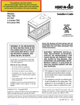
Figure 2. Diagram of the ST-HVB-IPI
5-14
(133mm)
12
(306mm)
1/2
(13mm)
(4)
46-5/8
(1183mm)
42
(1067mm) 32-5/16
(820mm)
21
(533mm)
36-3/16
(919mm)
2-5/16
(58mm)
4-3/4
(121mm)
4-1/16
(102mm)
4-1/2
(114mm)
ELECTRICAL
ACCESS
GAS LINE
ACCESS
12
(305mm)
4-1/2
(114mm)
2-9/16
(64mm)
24
(610mm)
8-1/2
(216mm)
34-3/4
(882mm)
Ø8
(204mm)
Ø8
(204mm)
REAR VENT
COLLARS
ELECTRICAL
ACCESS
GAS LINE
ACCESS
GAS CONTROLS
& LABELS SIDE GLASS
DOOR
TOP STANDOFFS
TOP VENT
COLLARS

Heat & Glo • PIER-HVB-IPI, ST-HVB-IPI • 2006-901 Rev. C • 12/07
14
3Installing the Fireplace
Step 1. Locating the Fireplace
The diagram below shows space and clearance require-
ments for locating a fireplace within a room.
Figure 4A. Fireplace Dimensions and Locations
Clearance Requirements
The top, back, and sides of the fireplace are defined by
stand-offs. The minimum clearance to a perpendicular wall
extending past the face of the fireplace is one inch (25 mm).
The metal ends of the fireplace may NOT be recessed into
combustible construction.
Note: Refer to Figure 4B for dimensions and appliance
locations if installing a Pier-HVB unit with a Catalina
shelf and/or marble package.
Note: Refer to the Catalina installation instruction
included with kit for assembly and installation.
Figure 4B.
50-1/2 in.
34-1/2 in.
7 in.
47-1/2 in.
45-1/4 in.
13/16 in.
Marble sizes (inches):
Header .................................. 26 x 8
Side headers .................. 45-1/2 x 8
Legs................................ 33-1/2 x 7
45 -1/4 in.
(1149mm)
FINISHED
WALL
Fireplace Locations/Dimensions with
Catalina Shelf/Marble Package ONLY
Note: This location diagram MUST be followed when in-
stalling a Pier-HVB with a Catalina shelf/marble package
since the fireplace is installed further from finished wall.
36"
GLASS
GLASS
36"
GLASS
GLASS
GLASS
36"
36"
PIER-HVB-IPI
TOP VIEW
ST-HVB-IPI
TOP VIEW

Heat & Glo • PIER-HVB-IPI, ST-HVB-IPI • 2006-901 Rev. C • 12/07 15
Minimum Clearances
from the Fireplace to Combustible Materials
Inches mm
Glass Sides or Ends .......... 36 .................... 914
Floor ................................... 0 ....................... 0
Rear Vent ...........................1/2 ..................... 13
Metal Sides or Ends .......... 1/2 ..................... 13
Top ................................... 2 1/2 ................... 64
Ceiling* .............................. 31 .................... 787
For minimum clearances, see the direct vent termination
clearance diagrams on pages 31 and 32 in this manual.
Minimum Clearances
from the Vent Pipe to Combustible Materials
Inches mm
Vertical Sections. ............. 1 ................ 25
Horizontal Sections
Top ..................................... 3 ................ 75
Bottom ............................... 1 ................ 25
Sides ................................. 1 ................ 25
At Wall Firestops
Top .................................. 2 1/2 ............ 63.7
Bottom .............................. 1/2 ............... 13
Sides ................................. 1 ................ 25
* The clearance to the ceiling is measured from the top of
the unit, excluding the standoffs (see Figures 37 & 38).
The distance from the unit to combustible construction is to
be measured from the unit outer wrap surface to the com-
bustible construction, NOT from the screw heads that se-
cure the unit together.
!
WARNING: FRAMING DIMENSIONS ASSUME
USE OF 1/2 INCH THICK WALL COVERING
MATERIALS ON EXTERIOR OF FRAMING ONLY AND
NO SHEETROCK ON INTERIOR OF FRAMING.
Step 2. Framing the Fireplace
Fireplace framing can be built before or after the fireplace is
set in place. Framing should be positioned to accommo-
date wall coverings and fireplace facing material. The dia-
gram below shows framing reference dimensions.
CAUTION: MEASURE FIREPLACE DIMENSIONS AND
VERIFY FRAMING METHODS AND WALL COVERING
DETAILS BEFORE FRAMING.

Heat & Glo • PIER-HVB-IPI, ST-HVB-IPI • 2006-901 Rev. C • 12/07
16
PIER-HV-IPI
ST-HV-IPI
D
B
C
A
A
C
B
E
Framing should be
constructed of 2 X 4
lumber or heavier.
Model A B C D E
PIER-HVB-IPI 42-1/8 42-1/2 23 35-3/4 48
ST-HVB-IPI 47-5/8 42-1/2 23 35-3/4 48
Figure 5. Framing Dimensions
NOTE: DIMENSIONS SHOWN IN INCHES
Shows center of 10” x 12” vent framing holes for top and rear venting. The
center of the hole is one inch (25.4mm) above the center of the horizontal
vent pipe.

Heat & Glo • PIER-HVB-IPI, ST-HVB-IPI • 2006-901 Rev. C • 12/07 17
NOTE: PIPES OVERLAP 1-1/4 INCHES
AT EACH JOINT.
Figure 6. DVP-Series Direct Vent Component Specifications (5-inch inner pipe / 8-inch outer pipe)
DVP90ST
12-9/16
11-1/4
7-1/4
1-1/4 TYP
1/2 TYP
8-9/16
DVP36
DVP48
48
24
36
4
6
DVP4
DVP6
12
DVP12
2
MIN.
DVP12A
12-3/16
MAX.
DVP24
9-7/8
45.0
O
10-1/4
DVP45
14-1/4

Heat & Glo • PIER-HVB-IPI, ST-HVB-IPI • 2006-901 Rev. C • 12/07
18
Figure 7. Vent System Components and Termination Kits
Step 3. Installing the Vent System
A. Vent System Approvals
These models are approved to use DVP series direct vent
pipe components and terminations (see Figures 6 and 7).
Approved vent system components are labeled for identifi-
cation. This pipe is tested and listed as an approved com-
ponent of the fireplace. The pipe is tested to be run inside
an enclosed wall. There is no requirement for inspection
openings at each joint within the wall. There is no required
pitch for horizontal vent runs. NO OTHER VENTING SYS-
TEMS OR COMPONENTS MAY BE USED.
Detailed installation instructions are included with each vent
termination kit and should be used in conjunction with this
Installers Guide.
The flame and ember appearance may vary based on the
type of fuel burned and the venting configuration used.
Identifying Vent Components
The vent systems installed on this gas fireplace may in-
clude one, two, or three 90° elbow assemblies. The rela-
tionships of vertical rise to horizontal run in vent configura-
tions using 90° elbows MUST BE strictly adhered to. The
rise to run relationships are shown in the venting drawings
and tables. Refer to the diagrams on the next several pages.
NOTE: Two 45° elbows may be used in place of one
90° elbow. Rise to run ratios in the vent system must
be followed if 45° elbows are used.
This model has a 450 elbow built into it. It may be posi-
tioned to vent either horizontal or vertical. Depending on the
installation, decide which direction the elbow should be fac-
ing. Remove the 8 screws from the corner cover plate. Po-
sition the 450 elbow as desired and replace the corner cov-
er plate with the 8 screws.
HORIZONTAL
TERMINATION
WALL FIRESTOP
90 DEGREE
ELBOW
PIPE LENGTH
CEILING
FIRESTOP
VERTICAL
TERMINATION
STORM COLLAR
ROOF FLASHING
Terminations Kits
(Required to have a minimum of 3
feet of vertical in the vent system)
DVP-TVPVK-80
DVP-TVHW
DVP-TRAP DVP-TB1
SERIES

Heat & Glo • PIER-HVB-IPI, ST-HVB-IPI • 2006-901 Rev. C • 12/07 19
Figure 8
NOTE: On vertical venting
configurations you may
want to install the flue re-
strictor (385-128). See flue
restrictor installation in-
structions.
Flue Restrictor Instructions
1. Locate the Flue Restrictor which is in the manual
bag.
Figure 10. Flue Restrictor
BREAK
HERE
Figure 9
2. Break the Flue Restrictor into two pieces. Do this
by bending the part back and forth until it breaks
(see Figure 10).
1 2 3 4 5
SETTINGS
1 2 3 4 5
4. Center the Flue Restrictor on vent and secure in
place using two self-tapping screws (see Figure 11).
STRAIGHT OUT
HORIZONTAL VENTING
H
Max. Run
24" (610 mm)
Figure 12.
V
CAP
H
3. Match the amount of
vertical in the system
with the chart to find the
appropriate position to
set the Flue Restrictor.
Figure 11
- CHART -
Vertical Settings
4' 1-1
8' 1-2
15' 2-2
20' 2-3
25' 3-3
30' 4-3
35' 4-4
40' 4-4
50' 4-5
FLUE
RESTRICTOR
STRAIGHT UP
VERTICAL VENTING
V (FT.)
50' MAX. (15.2 M)

Heat & Glo • PIER-HVB-IPI, ST-HVB-IPI • 2006-901 Rev. C • 12/07
20
Figure 14. Venting with One 90° Elbow
Figure 13. Venting with One 90° Elbow
V
H
H
V
NATURAL GAS - VENTING WITH ONE 90° ELBOW
V (FT.) H (FT.)
1' MIN. (305mm) 3' MAX. (914mm)
2' MIN. (610mm) 6' MAX. (1.83m)
3' MIN. (914mm) 9' MAX. (2.7m)
4' MIN. (1.22m) 12' MAX. (3.6m)
5’ MIN. (1.5m) 15’ MAX. (4.5m)
6’ MIN. (1.83m) 18’ MAX. (5.5m)
V + H = 50’ MAX. (15.2m)(11.3m)
PROPANE - VENTING WITH ONE 90° ELBOW
V (FT.) H (FT.)
1' MIN. (305mm) 2' MAX. (610mm)
2' MIN. (610mm) 4' MAX. (1.22m)
3' MIN. (914mm) 6’ MAX. (1.83m)
4' MIN. (1.22m) 8' MAX. (2.4m)
5’ MIN. (1.5m) 10' MAX. (3.0m)
6’ MIN. (1.83m) 12' MAX. (3.6m)
V + H = 50’ MAX. (15.2m)
NATURAL GAS
VENTING WITH ONE 90° ELBOW
V (FT.) H (FT.)
900 Elbow on top 2.5’ MAX. (64mm)
1' MIN. (305mm) 3' MAX. (914mm)
2' MIN. (610mm) 6' MAX. (1.83m)
3' MIN. (914mm) 9' MAX. (2.7m)
4' MIN. (1.22m) 12' MAX. (3.6m)
5’ MIN. (1.5m) 15’ MAX. (4.5m)
6’ MIN. (1.83m) 18’ MAX. (5.5m)
V + H = 50’ MAX. (15.2m)
PROPANE
VENTING WITH ONE 90° ELBOW
V (FT.) H (FT.)
900 Elbow on top 2’ MAX. (610mm)
1' MIN. (305mm) 2' MAX. (610mm)
2' MIN. (610mm) 4' MAX. (1.22m)
3' MIN. (914mm) 6’ MAX. (1.83m)
4' MIN. (1.22m) 8' MAX. (2.4m)
5’ MIN. (1.5m) 10' MAX. (3.0m)
6’ MIN. (1.83m) 12' MAX. (3.6m)
V + H = 50’ MAX. (15.2m)

Heat & Glo • PIER-HVB-IPI, ST-HVB-IPI • 2006-901 Rev. C • 12/07 21
Figure 15. Venting with Two 90° Elbows
H
1
H
V
V
V
1
H
NATURAL GAS
VENTING WITH TWO 90° ELBOWS
V (FT.) H + H1(FT.)
900 Elbow on top 2.5’ MAX. (64mm)
1' MIN. (305mm) 3' MAX. (914mm)
2' MIN. (610mm) 6' MAX. (1.83m)
3' MIN. (914mm) 9' MAX. (2.7m)
4' MIN. (1.22m) 12' MAX. (3.6m)
5’ MIN. (1.5m) 15’ MAX. (4.5m)
6’ MIN. (1.83m) 18’ MAX. (5.5m)
V + H + H1 = 50’ MAX. (15.2m)
PROPANE
VENTING WITH TWO 90° ELBOWS
V (FT.) H + H1(FT.)
900 Elbow on top 2’ MAX. (610mm)
1' MIN. (305mm) 2' MAX. (610mm)
2' MIN. (610mm) 4' MAX. (1.22m)
3' MIN. (914mm) 6’ MAX. (1.83m)
4' MIN. (1.22m) 8' MAX. (2.4m)
5’ MIN. (1.5m) 10' MAX. (3.0m)
6’ MIN. (1.83m) 12' MAX. (3.6m)
V + H + H1 = 50’ MAX. (15.2m)
NATURAL GAS
VENTING WITH TWO 90° ELBOWS
V + V1 (FT.) H (FT.)
900 Elbow on top 2.5’ MAX. (64mm)
1' MIN. (305mm) 3' MAX. (914mm)
2' MIN. (610mm) 6' MAX. (1.83m)
3' MIN. (914mm) 9' MAX. (2.7m)
4' MIN. (1.22m) 12' MAX. (3.6m)
5’ MIN. (1.5m) 15’ MAX. (4.5m)
6’ MIN. (1.83m) 18’ MAX. (5.5m)
V + V1 + H = 50’ MAX. (15.2m)
PROPANE
VENTING WITH TWO 90° ELBOWS
V + V1 (FT.) H (FT.)
900 Elbow on top 2’ MAX. (610mm)
1' MIN. (305mm) 2' MAX. (610mm)
2' MIN. (610mm) 4' MAX. (1.22m)
3' MIN. (914mm) 6’ MAX. (1.83m)
4' MIN. (1.22m) 8' MAX. (2.4m)
5’ MIN. (1.5m) 10' MAX. (3.0m)
6’ MIN. (1.83m) 12' MAX. (3.6m)
V + V1 + H = 50’ MAX. (15.2m)
H + H1 = 18’ MAX. (5.5m)
H + H1 = 12’ MAX. (3.6m)

Heat & Glo • PIER-HVB-IPI, ST-HVB-IPI • 2006-901 Rev. C • 12/07
22
Figure 16.
Venting with Two 90° Elbows
Figure 17. Venting with Two 90° Elbows
H
1
V
H
V
H
H
1
NATURAL GAS
VENTING WITH TWO 90° ELBOWS
V (FT.) H + H1(FT.)
1' MIN. (305mm) 3' MAX. (914mm)
2' MIN. (610mm) 6' MAX. (1.83m)
3' MIN. (914mm) 9' MAX. (2.7m)
4' MIN. (1.22m) 12' MAX. (3.6m)
5’ MIN. (1.5m) 15’ MAX. (4.5m)
6’ MIN. (1.83m) 18’ MAX. (5.5m)
V + H + H1 = 50’ MAX. (15.2m)
PROPANE
VENTING WITH TWO 90° ELBOWS
V (FT.) H + H1(FT.)
1' MIN. (305mm) 2' MAX. (610mm)
2' MIN. (610mm) 4' MAX. (1.22m)
3' MIN. (914mm) 6’ MAX. (1.83m)
4' MIN. (1.22m) 8' MAX. (2.4m)
5’ MIN. (1.5m) 10' MAX. (3.0m)
6’ MIN. (1.83m) 12' MAX. (3.6m)
V + H + H1 = 50’ MAX. (15.2m)
H + H1 = 12’ MAX. (3.6m)
H + H1 = 18’ MAX. (5.5m)

Heat & Glo • PIER-HVB-IPI, ST-HVB-IPI • 2006-901 Rev. C • 12/07 23
Figure 18. Venting with three 90° elbows
H
H
1
H
2
V
H
V
H
1
V
1
NATURAL GAS
VENTING WITH THREE 90° ELBOWS
V + V1 (FT.) H + H1+ H2(FT.)
1' MIN. (305mm) 3' MAX. (914mm)
2' MIN. (610mm) 6' MAX. (1.83m)
3' MIN. (914mm) 9' MAX. (2.7m)
4' MIN. (1.22m) 12' MAX. (3.6m)
5’ MIN. (1.5m) 15’ MAX. (4.5m)
6’ MIN. (1.83m) 18’ MAX. (5.5m)
V+ V1 + H + H1+ H2 = 50’ MAX. (15.2m)
PROPANE
VENTING WITH THREE 90° ELBOWS
V + V1(FT.) H + H1+ H2(FT.)
1' MIN. (305mm) 2' MAX. (610mm)
2' MIN. (610mm) 4' MAX. (1.22m)
3' MIN. (914mm) 6’ MAX. (1.83m)
4' MIN. (1.22m) 8' MAX. (2.4m)
5’ MIN. (1.5m) 10' MAX. (3.0m)
6’ MIN. (1.83m) 12' MAX. (3.6m)
V+ V1 + H + H1+ H2 = 50’ MAX. (15.2m)
H + H1+ H2 = 12’ MAX. (3.6m)
H + H1+ H2 = 18’ MAX. (5.5m)
NATURAL GAS
VENTING WITH THREE 90° ELBOWS
V + V1 (FT.) H + H1(FT.)
1' MIN. (305mm) 3' MAX. (914mm)
2' MIN. (610mm) 6' MAX. (1.83m)
3' MIN. (914mm) 9' MAX. (2.7m)
4' MIN. (1.22m) 12' MAX. (3.6m)
5’ MIN. (1.5m) 15’ MAX. (4.5m)
6’ MIN. (1.83m) 18’ MAX. (5.5m)
V+ V1 + H + H1 = 50’ MAX. (15.2m)
PROPANE
VENTING WITH THREE 90° ELBOWS
V + V1 (FT.) H + H1(FT.)
1' MIN. (305mm) 2' MAX. (610mm)
2' MIN. (610mm) 4' MAX. (1.22m)
3' MIN. (914mm) 6’ MAX. (1.83m)
4' MIN. (1.22m) 8' MAX. (2.4m)
5’ MIN. (1.5m) 10' MAX. (3.0m)
6’ MIN. (1.83m) 12' MAX. (3.6m)
V+ V1+ H + H1 = 50’ MAX. (15.2m)
H + H1 = 12’ MAX. (3.6m)
H + H1 = 18’ MAX. (5.5m)

Heat & Glo • PIER-HVB-IPI, ST-HVB-IPI • 2006-901 Rev. C • 12/07
24
Figure 19. Venting with three 90° elbows
V
H
H
1
V
1
V
H
H
1
V
1
NATURAL GAS
VENTING WITH THREE 90° ELBOWS
V + V1 (FT.) H + H1(FT.)
900 Elbow on top 2.5’ MAX. (64mm)
1' MIN. (305mm) 3' MAX. (914mm)
2' MIN. (610mm) 6' MAX. (1.83m)
3' MIN. (914mm) 9' MAX. (2.7m)
4' MIN. (1.22m) 12' MAX. (3.6m)
5’ MIN. (1.5m) 15’ MAX. (4.5m)
6’ MIN. (1.83m) 18’ MAX. (5.5m)
V+ V1 + H + H1 = 50’ MAX. (15.2m)
PROPANE
VENTING WITH THREE 90° ELBOWS
V + V1 (FT.) H + H1(FT.)
900 Elbow on top 2’ MAX. (610mm)
1' MIN. (305mm) 2' MAX. (610mm)
2' MIN. (610mm) 4' MAX. (1.22m)
3' MIN. (914mm) 6’ MAX. (1.83m)
4' MIN. (1.22m) 8' MAX. (2.4m)
5’ MIN. (1.5m) 10' MAX. (3.0m)
6’ MIN. (1.83m) 12' MAX. (3.6m)
V+ V1+ H + H1 = 50’ MAX. (15.2m)
H + H1 = 12’ MAX. (3.6m)
H + H1 = 18’ MAX. (5.5m)

Heat & Glo • PIER-HVB-IPI, ST-HVB-IPI • 2006-901 Rev. C • 12/07 25
1. Attach the First Vent Component to the
Starting Collars
To attach the first vent component to the starting collars
of the fireplace:
• Slide the first vent section onto the unit and push in until
they snap lock in position.
• Rotate this section to the desired position.
• Using the two tabs provided on the elbow cover plate,
secure the first section of venting to the fireplace with
two screws.
Refer to Cinch Pipe and Termination Cap installation
instructions.
If the installation is for a termination cap attached directly
to the fireplace, skip to the sections, Install Firestops and
Vent Termination.
B. Installing Vent Components
After determining which direction the 45O elbow will be used
follow venting instructions accordingly.
• This fireplace comes ready to vent vertically.
• To vent off the unit horizontally, the elbow cover plate
must first be removed from the unit (see Figure 20).
• The elbow can be removed from the unit by aligning the
seams of the elbow to the arrows on the surrounding
heat shield (see Figure 21).
• Position the elbow in the vertical position. Snap in place
with the starting collar.
• Replace the elbow cover plate aligning it with the elbow
and secure in place with the 8 screws.
• Place the rope ring around the first section of pipe and
slide it up against the cover plate.
NOTE: The rope ring is needed for the heat manage-
ment and to prevent cold air infiltration.
Venting Out Vertically
If the vertical vent component is over 4 feet, you may want
to install the flue restrictor (located in the bag containing
the install manual) to improve flame appearance. Center
the flue restrictor on the 5” flue being used, and with self
tapping screws secure the restrictor to the inside of the
firebox as shown in Figure 22.
Figure 20
Figure 22
FLUE
RESTRICTOR
ELBOW COVER PLATE
Figure 21 TOP VIEW
HEAT
SHIELD ARROWS
ELBOW
ELBOW
SEAM
FRONT VIEW
/