Page is loading ...

EN
Operating Manual
Precision Pressure Transmitter in IS-Areas
AX2-x|act ci, AX2-x|act i, AX2-XMP ci a AX2-XMP i
AX7-XMP ci, AX7-XMP i
Headquarter Eastern Europe
BD SENSORS s.r.o.
Hradišťská 817
CZ - 687 08 Buchlovice
Czech Republic
Tel.: +420 572 411 011
Fax: +420 572 411 497
Headquarter Western Eu-
rope / International
BD SENSORS GmbH
BD-Sensors-Str. 1
D - 95199 Thierstein
Germany
Tel.: +49 (0) 92 53 / 98 11-0
Fax: +49 (0) 92 53 / 98 11-11
Russia
BD SENSORS RUS
39a, Varshavskoe shosse
RU - Moscow 117105
Russia
Tel: +7 (0) 9 59 81 / 09 63
Fax: +7 (0) 9 57 95 / 07 21
further agencies in:
EUROPE
• Belgium
• Denmark
• Finland
• France
• Great Britain
• Greece
• Italy
• Lithuania
• Luxemburg
• Netherlands
• Norway
• Poland
• Portugal
• Romania
• Sweden
• Switzerland
• Slovakia
• Spain
• Turkey
• UK
• Ukraine
AFRICA
• Egypt
• South Africa
ASIA
• India
• Iran
• Israel
• Japan
• Kazakhstan
• Malaysia
• Singapore
• Taiwan
• Thailand
• Vietnam
AUSTRALIA
The addresses of our distribution partners are listed on our
homepage www.bdsensors.com. It is possible to download
data sheets, operating manuals, ordering codes and certifi-
cates, as well.
Table of contents
1. General information
2. Product identification
3. Mechanical installation
4. HART
communication
5. Special regulations for IS-areas
6. Electrical Installation
7. Initial start-up
8. Operation
9. Error handling
10. Placing out of service
11. Maintenance
12. Service / Repair
13. Disposal
14. Warranty conditions
15. Declaration of conformity / CE
1. General information
1.1 Information on the operating manual
This operating manual contains important information on
proper usage of the device. Read this operating manual care-
fully before installing and starting up the pressure measuring
device.
Adhere to the safety notes and operating instructions which
are given in the operating manual. Additionally applicable reg-
ulations regarding occupational safety, accident prevention as
well as national installation standards and engineering rules
must be complied with!
For the installation, maintenance and cleaning of the device,
you must absolutely observe the relevant regulations and
stipulations on explosion protection (VDE 0160, VDE 0165 or
DIN EN 60079-14) as well as the occupational safety provi-
sions.
The device was constructed acc. to standards EN IEC
60079-0:2018, EN 60079-11, EN 60079-26.
This operating manual is part of the device, must be kept near-
est its location, always accessible to all employees.
This operating manual is copyrighted. The contents of this op-
erating manual reflect the version available at the time of print-
ing. It has been issued to our best knowledge. However, errors
may have occurred. BD SENSORS is not liable for any incor-
rect statements and their effects.
– Technical modifications reserved –
1.2 Symbols used
DANGER! – dangerous situation, which may result in
death or serious injuries
WARNING! – potentially dangerous situation, which may
result in death or serious injuries
CAUTION! – potentially dangerous situation, which may
result in minor injuries
!
CAUTION! – potentially dangerous situation, which may
result in physical damage
NOTE – tips and information to ensure a failure-free
operation
1.3 Target group
WARNING! To avoid operator hazards and damages of
the device, the following instructions have to be worked
out by qualified technical personnel.
1.4 Limitation of liability
Failure to observe the instructions or technical regulations, im-
proper use and use not as intended, and alteration of or dam-
age to the device will result in the forfeiture of warranty and
liability claims.
1.5 Intended use
- The precision pressure transmitters xact ci and
xact i has been specially designed for food industry,
pharmacy and biotechnology. They are configurable via
display and operating module as standard.
- The precisions pressure transmitters XMP ci and
XMP i are intended for applications in process industry,
chemical and petrochemical industry. They offer HART
®
-
communication as standard.
- The device is intended for converting the physical pa-
rameter of pressure into an electric signal. It has to be
used only for this purpose, considering the following in-
formation.
- The above listed pressure transmitters have, according
to the type, been developed for applications in overpres-
sure and vacuum as well as for absolute pressure meas-
urement.
- Devices with 3-A and / or EHEDG certified process con-
nection have been developed especially for applications
in food and pharmaceutical industry. The process con-
nection is hygienic and can be sterilized.
- Permissible measuring and cleaning media are gases or
liquids, which are compatible with the media wetted parts
of the device (according to data sheet) and your system.
This must be ensured for the application.
- This operating manual applies to devices with explosion
protection approval and is intended for the use in IS-ar-
eas. A device has an explosion protection approval if this
has been specified in the purchase order and confirmed
in our order confirmation. In addition, the manufacturing
label contains the -symbol.
- It is the operator's responsibility to check and verify the
suitability of the device for the intended application. In ad-
dition it has to be ensured, that the medium is compatible
with the media wetted parts. If any doubts remain, please
contact our sales department in order to ensure proper
usage. BD SENSORS is not liable for any incorrect se-
lections and their effects!
- The technical data listed in the current data sheet are en-
gaging and must be complied with. If the data sheet is not
available, please order or download it from our homep-
age. (http://www.bdsensors.com/products/down-
load/datasheets)
WARNING! Danger through improper usage!
Only use the device in permissible media and in accor-
dance with its intended use.
- Do not use the device as a ladder or climbing aid.
- The device must not be altered or modified in any way.
- BD SENSORS is not liable for damage caused by im-
proper or incorrect use.
NOTE -
Excessive dust accumulation and complete
coverage with dust must be prevented!
1.6 Safety technical maximum values
1.6.1 Intrinsically safe version
AX2-XMP i / AX2- XMP ci and AX2-x|act i / AX2-x|act ci
IBExU05ATEX1105 X
permissible temperatures for environment:
application in zone 0 (p
atm
0.8 bar up to 1.1 bar):
-20 ... 60 °C
application in zone 1 and 2: -40 ... 70 °C
supply and signal circuit:
U
i
= 28 V, I
i
= 98 mA, P
i
= 680 mW, C
i
≈ 0 nF, L
i
≈ 0 µH
plus cable inductivity 1 µH/m and cable capacity 160
pF/m (for cable by factory)
the supply connections have an inner capacity of max.
33 nF to the housing
NOTE - The limit values are valid only for the devices with
own-sure circuits!
1.6.2. Special conditions for safe use
- The equipment designed with connector have to be in-
stalled in such a way, that the Degree of protection IP20
always will be kept.
- The safety and assembly notes contained in the operat-
ing instructions and the Ambient temperature range from
-40 °C to +70 °C have to be observed.
- At pressure transmitter with the marking category ½
equipment, the sensor diaphragm serves as partition wall
and has to be protected against mechanical damages.
- The isolation of the intrinsically circuit opposite the case
is because of leakage flows in the blocking capacitors
from the EMV-boards limited.
1.6.3 Flameproof enclosure
AX7-XMP ci and AX7-XMP i
for aluminum die cast case:
IBExU 12 ATEX 1073 X
zone 1: II 2G Ex db IIC T5 Gb
permissible temperatures: -20 ... 70 °C
NOTE – The use of the devices with flameproof
enclosure is not allowed in the areas of dust!
1.6.4. Special conditions for safe use
- The pressure transmitters type AX7-XMP i, AX7-XMP ci
and AX7-XMD can be used in an ambient temperature range
from -20°C up to +70 °C.
- The cable entry (M20x1.5) supplied by the manufac-
turer may be used only for fixed installation. The operating
company has to ensure an appropriate clamping.
1.7 Package contents
Please verify that all listed parts are included in the delivery
and check for consistency specified in your order:
- precision pressure transmitter
- protective cap
- for mechanical pressure ports DIN 3852: o-ring (pre-
mounted)
- this operating manual
- for optional SIL2 version: safety data sheet
1.8 UL-approval (for devices with UL marking)
The UL approval was effected by applying the US standards,
which also conform to the applicable Canadian standards on
safety.
Observe the following points so that the device meets the
requirements of the UL approval:
- only indoor usage
- maximum operating voltage: according to data sheet
- The device must be operated via a supply with energy limi-
tation (acc. to UL 61010) or an NEC Class 2 energy supply.
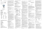
2. Product identification
The device can be identified by its manufacturing label. It pro-
vides the most important data. By the ordering code the prod-
uct can be clearly identified.
!
The manufacturing label must not be removed from the
device!
3. Mechanical installation
3.1 Mounting and safety instructions
WARNING! Install the device only when depressurized
and currentless!
WARNING! This device may only be installed by qualified
technical personnel who has read and understood the
operating manual!
DANGER! Caused by the explosion hazard following in-
structions have to be complied with:
-
The technical data listed in the EC type-examination
certificate are engaging and must absolutely be
complied with. If the certificate is not available,
please order or download it from our homepage:
http://www.bdsensors.com
- Working on supplied (active) parts, except for intrin-
sically safe circuits, is principally prohibited during
an explosion hazard.
- Make sure that an equipotential bonding is in place
for the entire course of the line, both inside and out-
side the intrinsic area.
- In case of increased danger of lightning strike or
damage by overvoltage, a stronger lightning protec-
tion should be planned.
- Observe the limiting values specified in the EC type-
examination certificate. (Capacitance and induct-
ance of the connection cable are not included in the
values.)
- Make sure that the entire interconnection of intrinsi-
cally safe components remains intrinsically safe.
The operator is responsible for the intrinsic safety of
the overall system (installation of intrinsic parts).
- Do not mount the device in a pneumatic flow rate!
- Excessive dust deposits (over 5 mm) and a com-
plete dust covering must be avoided!
- When installing the device, at least the ingress pro-
tection IP 20 must be realised.
!
Handle this high-sensitive electronic precision measuring
device with care, both in packed and unpacked condition!
!
There are no modifications/changes to be made on the
device.
!
Provide a cooling line when using the device in steam
piping and clarify the material compatibility.
!
The measuring point must be designed in such a way that
cavitation and pressure surges are avoided.
!
Do not throw the package/device!
!
To avoid damaging the diaphragm, remove packaging
and protective cap directly before starting assembly. The
delivered protective cap has to be stored!
!
Place the protective cap on the pressure port again
immediately after disassembling.
!
Handle the unprotected diaphragm very carefully - it is
very sensitive and may be easily damaged.
!
Do not use any force when installing the device to pre-
vent damage of the device and the plant!
!
For installations outdoor and in damp areas following
these instructions:
- To prevent moisture admission in the plug the de-
vice should be installed electrically after mounting,
at once. Otherwise a moisture admission has to be
blocked e.g. by using a suitable protection cap. (The
ingress protection in the data sheet is valid for the
connected device.)
- Choose an assembly position, which allows the
flow-off of splashed water and condensation. Avoid
permanent fluid at sealing surfaces!
- When using a device with cable outlet, turn the out-
going cable downwards. If the cable has to be
turned upwards, then point it downward so the mois-
ture can drain.
- Install the device in such a way that it is protected
from direct solar irradiation. Direct solar irradiation
can lead to the permissible operating temperature
being overstepped in the worst case. This is
prohibited for applications in IS-areas!
When installing the device to the pressurized system, the
operator has to ensure the correct sealing.
Check the intended resp. delivered seal for compatibility
with the medium. If there is no compatibility, take a suit-
able seal.
Take note that no assembly stress occurs at the pressure
port, since this may cause a shifting of the characteristic
curve. This is especially important for very small pressure
ranges as well as for devices with a pressure port made
of plastic.
In hydraulic systems, position the device in such a way
that the pressure port points upward (ventilation).
Provide a cooling line when using the device in steam
piping.
3.2 General installation steps
- Carefully remove the pressure measuring device from
the package and dispose of the package properly.
- Go ahead as detailed in the specific instructions below.
3.3 Installation steps for DIN 3852
- Check to ensure the proper groove fitting of the o-ring
and additionally to ensure no damage to the o-ring.
- Ensure that the sealing surface of the taking part is per-
fectly smooth and clean.
- Screw the device into the corresponding thread by
hand.
- Devices with a spanner flat have to be tightened with an
open-end wrench (wrench size of steel: G1/2": approx.
10 Nm; G1": approx. 20 Nm; G1 1/2": approx. 25 Nm;
wrench size of plastic: max. 3 Nm).
3.4 Installation steps for EN 837
- Use a suitable seal, corresponding to the medium and
the pressure input (e. g. a cooper gasket).
- Ensure that the sealing surface of the taking part is per-
fectly smooth and clean.
- Screw the device into the corresponding thread by
hand.
- Tighten it with a wrench (for G1/2": approx. 50 Nm).
3.5 Installation steps for NPT connections
- Use a suitable seal, corresponding to the medium and
the pressure input (e. g. a PTFE-strip).
- Screw the device into the corresponding thread by
hand.
- Tighten it with a wrench (for 1/2" NPT: approx. 70 Nm).
3.6 Installation steps for G1" cone
- Screw the device into the corresponding thread by hand.
(metallic sealing)
- Tighten the devices with an open-end wrench
(P
N
< 10 bar: 30 Nm; P
N
≥ 10 bar: 60 Nm).
3.7 Installation steps for dairy pipe connections
- Check to ensure that the O-ring fits properly into the in-
tended groove in the mounting part.
EHEDG conformity is only ensured in combination with an
approved seal. This is e.g.:
- ASEPTO-STAR k-flex upgrade seal by Kieselmann
GmbH
- Center the dairy pipe connection in the counterpart.
- Screw the cup nut onto the mounting part.
- Then tighten it with a hook wrench.
3.8 Installation steps for Clamp and Varivent
connections
- Use a suitable seal corresponding to the medium and
the pressure input.
- Put the seal onto the corresponding mounting part.
EHEDG conformity is only ensured in combination with an
approved seal. This is e.g.:
for Clamp connections: T-ring seal from Combifit Internatio-
nal B.V.
- for Varivent
connections: EPDM-O-ring which is FDA-
listed
- Center the Clamp or Varivent
connection on the fitting
counterpart with seal.
- Then fit the device with a suitable fastening element
(e. g. semi-ring or retractable ring clamp) according to
the supplier’s instructions.
3.9 Installation steps for DRD and connecting flanges
- Use a suitable seal corresponding to the medium and
pressure input. (e. g. a fiber gasket).
- Put the seal between connecting flange and counter
flange.
- Install the device with 4 resp. 8 screws (depending on
flange version) on the counter flange.
3.10 Positioning of the display and operating module
(standard with x|act, optionally for XMP)
The display and operating module is continuously rotatable so
that clear readability is guaranteed even in unusual installation
positions. To change the position go ahead as follows:
- Screw off the metal cap by hand.
- Turn the display and operating module carefully into the
desired position by hand. The module is equipped with a
rotational limiter.
- Before screwing on the cap again, the o-ring and sealing
surfaces of the housing have to be checked for damage
and if necessary have to be changed!
- Afterwards screw the metal cap on by hand and make
sure that the housing is firmly locked again.
WARNING! It is prohibited to open and configure the de-
vices in the presence of explosion hazards. Therefore it
is recommended to position the display and operating
module together with the mechanical installation.
!
Pay attention that no moisture can enter the device.
Moreover, the seals and the sealing surfaces should not
get dirty, as this may cause a reduction of the degree of
protection depending on the case of application or place
of installation. This can lead to a breakdown of the de-
vices or to irreparable damages on the device.
3.11 Conditions for devices with 3-A symbol and
/ or EHEDG certificate
!
The device or its connecting piece must be installed in
such a way that the surfaces are self-draining (permis-
sible installation position 273° … 87°).
!
Make sure that the welding socket is mounted flush in-
side the tank.
!
The user is responsible for:
!
- the correct size of the seal and the choice of an elasto-
meric sealing material that complies with the 3-A and /
or EHEDG standard(s)
!
- an easy to clean installation position of the pressure
transmitter with little dead space, as well as definition /
verification / validation of a suitable cleaning process
!
- defining adequate service intervals
4. HART
communication
(standard with XMP, optional for x|act)
DANGER! It is prohibited to interrupt the intrinsically safe
circuit in the presence of explosion hazards in order to
loop in a HART
communication interface (HART
-com-
municator or HART
-modem).
The analogue output signal is overridden by an additional sig-
nal according to the HART
-specification. The device can be
configured via a HART
-communication device. Therefore we
suggest our programming kit CIS 150 (available as acces-
sory).
To ensure a trouble-free operation the following require-
ments should be fulfilled:
maximal cable length between device and power supply:
VVV
CCR
L
36
max
10401065 ⋅
−
⋅
⋅
=
whereas L
max
: maximum length of cable in [m]
R
V
: resistance of the cable together with
the load resistance in [Ω]
C
V
: capacity of the cable in [pF/m]
resistance R:
Ω
−
=024.0 12U
R
whereas U: power supply in [V
DC
]
The resistance must be at least 240 Ω.
5. Special regulations for IS-areas
5.1 Protection against electrostatic charge hazards
Different types of the device partially consist of chargeable
plastic components. These are in particular coating of the
housing as well as the plastic pressure port (optionally). A po-
tential electrostatic charge presents the danger of spark gen-
eration and ignition. An electrostatic charge must therefore be
absolutely prevented.
Generally, a shielded cable must be used.
Avoid friction on the plastic surfaces!
Do not clean the device dry! Use, for example, a damp
cloth.
The following warning sign is, if applicable, attached to the de-
vice. It points once more to the hazard of electrostatic charg-
ing.
Fig. 2 warning sign
!
The warning sign must not be removed from the device!
5.2 Overvoltage protection
If the device is used as electrical equipment of category 1 G,
a suitable overvoltage protection device must be connected in
series (attend the valid regulations for operating safety as well
as EN60079-14).
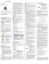
5.3 Schematic circuit
The operation of an intrinsically safe transmitter in intrinsic
safe areas requires special care when selecting the necessary
Zener barrier or transmitter repeater devices to allow the utili-
zation of the device’s properties to the full extent.
The following diagram shows a typical arrangement of power
supply, Zener barrier and pressure transmitter.
standard with XMP
optionally for x|act:
www.bdsensors.com
BA_XACT-XMP_EX_E_SRO
Fig. 1 manufacturing label – for AX2- example
safety tech-
nical maxi-
mum values
Ex-designation and
number of EC type examination certificate
ordering code
supply
setting range
signal
serial
number
code of
nominal range
Fig. 3 circuit diagrams

BA_XACT-XMP_EX_E_SRO_05.01.2021
Please pay attention to item (17) of the type examination cer-
tificate, which stipulates special conditions for intrinsically safe
operation.
5.4 Exemplary circuit description
The supply voltage of e. g. 24 V
DC
provided by the power sup-
ply is led across the Zener barrier. The Zener barrier contains
series resistances and Zener diodes as protective compo-
nents. Subsequently, the operating voltage is applied to the
device and, depending on the pressure a particular signal cur-
rent will flow.
DANGER! When installing the intrinsically safe device as
a zone-0-equipment, the supplying must be carried out
by a power supply which must be galvanically insulated
and which is not allowed to be grounded.
5.5 Functional selection criteria for Zener barriers and
galvanic power supply
The minimum supply voltage V
S
min
of the device must not fall
short since a correct function of the device can otherwise not
be guaranteed. The minimum supply voltage has been de-
fined in the respective product-specific data sheet under "Out-
put signal / Supply".
When using a galvanically insulated amplifier with a linear
bonding, please attend that the terminal voltage of the device
will decrease like it does with a Zener barrier. Furthermore, it
has to be attended that the supply of the device will also de-
crease with an optionally used signal amplifier.
5.6 Test criteria for the selection of the Zener barrier
In order not to fall below V
S min
, it is important to verify which
minimum supply voltage is available at full level control of the
device. Full level control, i. e. a maximum or nominal output
signal (20 mA), can be reached by applying the maximum
physical input signal (pressure).
The technical data of the barrier will usually provide the infor-
mation needed for the selection of the Zener barrier. However,
the value can also be calculated. If a maximum signal current
of 0.02 A is assumed, then – according to Ohm’s law – a par-
ticular voltage drop results on the series resistance of the Ze-
ner barrier. This voltage drop is subtracted from the voltage of
the power supply and as a result, the terminal voltage is ob-
tained which is applied on the device at full level control. If this
voltage is smaller than the minimum supply voltage, another
barrier or a higher supply voltage should be chosen.
Please pay attention when choosing the barrier or the
transmitter repeater because some supplied devices /
Zener barriers are not suitable for HART
communica-
tion. Most manufacturers offer a device group especially
developed for this application.
When selecting the ballasts, the maximum operating con-
ditions according to the EC type-examination certificate
must be observed. When assessing these, refer to their
current data sheets to ensure that the entire interconnec-
tion of intrinsically safe components remains intrinsically
safe.
6. Electrical Installation
WARNING! Install the device in currentless environ-
ments only!
U
WARNING! Install the connection for devices equipped
with terminal clamps so that the separating spaces com-
ply with the standard and the connecting lines cannot be
loosened.
U
By devices with pressure flameproof enclosure a cable
gland M20x1.5 with the name HSK-M-Ex-d / metric is
prescribed. This is already premounted. Technical data:
Cable diameter Ø 10... Ø 14 mm, key width: 24 mm, long-
term permissible temperature:-60... 105 °C, certificate: II
2G Ex db IIC T5 Gb.
U
DANGER! Danger of explosion when surpassing the
maximum supply of 28 V
DC
!
NOTE – The cap for the connection clamps and display
can be opened only if a locking protection, headless
screw with inside hexagonal, remove became. The screw
is on the right side below the cap. After attach of the cap
for display and for the connection clamps, the locking
protection must be screwed again purely. Besides, the
lubrication of the thread ways is not necessary.
NOTE - The cable gland by devices with flameproof
enclosure is suitable only for the firm transfer!
Establish the electrical connection of the device according to
the technical data shown on the manufacturing label, the
following table and the wiring diagram.
Pin configuration x|act:
Electrical
connections M12x1
(4-pin) cable colours
(DIN 47100)
Supply +
Supply –
1
3 wh (white)
bn (brown)
Shield
plug housing gn/ye (green / yellow)
Pin configuration XMP:
Terminal
clamps
aluminium die cast
case: terminal
clamps
clamp section: 2.5 mm
2
stainless steel
field housing:
clamp section: 1.5 mm
2
Supply +
Supply –
Test
1
IN+
IN–
Test
IN+
IN–
-
Shield
1
by connecting an ampere meter between the terminals Supply + and Test,
the output signal can be measured without disconnecting the power supply
Wiring diagrams:
2-wire-system (current)
2-wire-system (current) HART
!
For the installation of a device with cable outlet following
bending radiuses have to be complied with:
cable without ventilation tube:
static installation : 8-fold cable diameter
dynamic application: 12-fold cable diameter
cable with ventilation tube:
static installation : 10-fold cable diameter
dynamic application: 20-fold cable diameter
!
Prevent the damage or removal of the PTFE filter which
is fixed over the end of the air tube on devices with cable
outlet and integrated air tube.
!
To install a device with terminal clamps, the cap has to
be screwed off. If the device is equipped with a display
and operating module, this has to be pulled out carefully.
Put it as long as installing the device non-tensioned next
to the housing. Next insert it again carefully and ensure
that the cords are not turned or squeezed. Before screw-
ing on the cap again, the o-ring and sealing surfaces of
the housing have to be checked for damage and if
necessary to be changed! Afterwards screw the metal
cap on by hand and make sure that the field housing is
firmly locked again.
!
For a clear identification, the intrinsically safe cables are
marked with light blue shrink tubing (over the cable insu-
lation). If the cable has to be modified (e. g. shortened)
and the marking at the cable end has been lost in the
process, it must be restored (for example, by marking it
again with light blue shrink tubing or an appropriate iden-
tification label).
For the electrical connection a shielded and twisted
multicore cable has to be used.
7. Initial start-up
WARNING! Before start-up, the user has to check for
proper installation and for any visible defects.
WARNING! The device can be started and operated by
authorized personnel only, who have read and under-
stood the operating manual!
WARNING! The device has to be used within the tech-
nical specifications, only (compare the data in the data
sheet and the EC type-examination certificate)!
8. Operation (standard with x|act,
optionally for XMP)
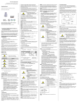
8.1 Display and operating module
A bargraph is shown in the display, indicating the current pres-
sure input as percentage of the specified pressure range. The
indication of the measured value as well as the configuration
of the individual parameters occurs through a menu via the
display. The individual functions can be set with the help of
three miniature push buttons located under the metal cap. For
devices of the XMP series with aluminium die cast case, ad-
ditionally the possibility is given to operate via three push but-
tons (accessible from above). This is especially an advantage
in IS-areas, caused by the fact that the device can be config-
ured in situ without opening the operating and display module.
Therefore the metal plate (on the top side of the device), has
to be folded backwards after loosening the right screw. The
definition of the three buttons is: ▼, OK, ▲ (starting at the left
side).
The menu system is a closed system allowing you to scroll
both forward and backward through the individual set-up
menus to navigate to the desired setting item. All settings are
permanently stored in a Flash EPROM and therefore available
even after disconnecting from the supply voltage.
WARNING! It is prohibited to open and configure the de-
vices in the presence of explosion hazards. After config-
uration it must be ensured that the device is completely
closed again outside the explosion hazard area.
!
Pay attention that no moisture can enter the device dur-
ing configuration. Moreover, the seals and the sealing
surfaces should not get dirty, as this may cause a reduc-
tion of the degree of protection depending on the case of
application or place of installation. This can lead to a
breakdown of the device or to irreparable damages on
the device. Right after configuration, the metal cap has to
be screwed on again.
8.2 Structure of the menu system
See arranged supplementary sheet (supplementary sheet /
structure of the menu system). This supplementary sheet
should only be used with this operating manual.
8.3 Menu list
-
▲-button: with this button you move forward in the
menu system or increase the displayed value; it will also
lead you to the operating mode (beginning with
menu item "1 DISPLAY")
-
▼-button: with this button you move back in the menu
system or decrease the displayed value; it will also lead
you to the operating mode (beginning with menu item
"5 SERVICE")
-
OK-button: with this button menu items and set values
have to be confirmed
execution of configuration:
- set the desired menu item by pushing the ▲- or ▼-button
- activate the set menu item by pushing the OK-button
- set the desired value or select one of the offered settings
by using the ▲- or ▼-button
- store/confirm the set value/selected setting and exit the
menu by pushing the OK-buttony
10. Placing out of service
WARNING! Disassemble the device only in current and
pressure less condition! Check before disassembly, if it
is necessary to drained off the media before dismantling!
WARNING! Depending on the medium, it may cause
danger for the user. Comply therefore with adequate pre-
cautions for purification.
11. Maintenance
In principle, this device is maintenance-free. If desired, the
housing of the device can be cleaned when switched of using
a damp cloth and non-aggressive cleaning solutions.
During the cleaning processes, note the compatibility of the
cleaning media used in combination with the media-wetted
materials of the pressure measuring devices. Permissible
concentrations and temperatures must be observed. Verifica-
tion/ validation by the user is essential.
Deposits or contamination may occur on the diaphragm/ pres-
sure port in case of certain media. Depending on kind and
quality of the process, suitable cyclical maintenance intervals
must be specified by the operator. As part of this, regular
checks must be carried out regarding corrosion, damage of
diaphragm/seal(s) and signal shift. A periodical replacement
of the seal(s) may be necessary.
Depending on the measuring medium, however, the dia-
phragm may be polluted or coated with deposit. If the medium
is known for such tendencies, the user has to set appropriate
cleaning intervals. After placing the device out of service cor-
rectly, the diaphragm can usually be cleaned carefully with a
non-aggressive cleaning solution and a soft brush or sponge.
If the diaphragm is calcified, it is recommended to send the
device to BD SENSORS for decalcification. Please read there-
fore the chapter “Repair” below.
!
An incorrect cleaning can cause irreparable damages on
the diaphragm. Never use spiky objects or pressured air
for cleaning the diaphragm.
12. Service / Repair
12.1 Recalibration
During the life-time of a transmitter, the value of offset and
span may shift. As a consequence, a deviating signal value in
reference to the nominal pressure range starting point or end
point may be transmitted. If one of these two phenomena oc-
curs after prolonged use, a recalibration is recommended to
ensure furthermore high accuracy.
12.2 Return
Before every return of your device, whether for recalibration,
decalcification, modifications or repair, it is necessary to con-
tact us to ensure a fast handling of your request. Please inform
us by sending an email to: [email protected]. Include the
number of devices sent and request a RMA. Then clean the
device and pack it shatterproof before send it to BD SEN-
SORS indicating the RMA.
13. Disposal
The device must be disposed according to the Eu-
ropean Directives 2002/96/EC and 2003/108/EC
(on waste electrical and electronic equipment).
Waste of electrical and electronic equipment may
not be disposed by domestic refuse!
WARNING! Depending on the measuring medium, deposit
on the device may cause danger for the user and the en-
vironment. Comply with adequate precautions for purifi-
cation and dispose of it properly.
14. Warranty conditions
The warranty conditions are subject to the legal warranty pe-
riod of 24 months from the date of delivery. In case of improper
use, modifications of or damages to the device, we do not ac-
cept warranty claims. Damaged diaphragms will also not be
accepted. Furthermore, defects due to normal wear are not
subject to warranty services.
15. Declaration of conformity / CE
the EC declaration of conformity, which is available
online at: http://www.bdsensors.cz., Additionally, the oper-
ational safety is confirmed by the CE sign on the manufactur-
ing label.
Addition
Mal-
func-
tion Possible cause Error detection / corrective
display
does not
work
falsely connected inspect the connections
line break inspect all connecting lines of the device
(including the connector plugs)
defective energy
supply inspect the power supply and the applied
supply voltage at the transmitter
no output
signal
wrong connected inspect the connection
line break inspect all line connections necessary to
supply the device (including the connector
plugs)
defective am-
peremeter (signal
input)
inspect the amperemeter (fine-wire fuse)
or the analogue input of the PLC
analogue
output
signal too
low
load resistance too
high verify the value of the load resistance
supply voltage too
low verify the output voltage of the power sup-
ply
defective energy
supply inspect the power supply and the applied
supply voltage at the device
small shift
of output
signal
diaphragm is highly
contaminated
careful cleaning with non-aggressive
cleaning solution and a soft brush or
sponge; incorrect cleaning can cause ir-
reparable damages on diaphragm or seals
diaphragm is calci-
fied or coated with
deposit
if possible it is recommended to send the
device to BD SENSORS for decalcification
or cleaning
large shift
of output
signal
diaphragm is dam-
aged (caused by
overpressure or
manually)
check the diaphragm; if it is damaged,
please send the device to BD SENSORS
for repair
measured
value
(display
and ana-
logue out-
put) devi-
ates from
the nomi-
nal value
high pressure /
pressure peaks
a recalibrated or replaced of the pressure
port by BD SENSORS is necessary
mechanical damage
to diaphragm
constant
output
signal at
4 mA
wrong ID-number ensure in the menu item "ID" that the set
value for the ID-number is "0000"
OK-button
bargraph
▼-button ▲-button
display
Fig. 4 touch pad
p supply +
supply –
VS
I
supply +
supply –
VS
A
p
I
If a parameter is configurable by a value, each digit may be configured separately. That means after activating
such a menu item (e. g. "2.3.1 OFFSET") by pushing the OK-button, the first digit of the currently set value will
start to blink. Now scroll up or down to the desired digit via the ▼- or ▲-button and confirm it with the OK-
button. After that, the next digit will start to blink. Configure it in the same way. In the menu items "2.3.1
OFFSET" and "2.3.2 FINALVAL", the decimal point will then start to blink and it is also possible to change its
position by using the ▼- or ▲-button. By confirming the position with the OK-button, the total value will be
stored if permissible. If the value is out of range, an error message (e. g. Error 03) will appear in the display
and the set value will not be stored. If you intend to set a negative value, the first digit has to be configured
with the ▼-button.
1 DIPLAY
Display
1.1 P
max
Maximum pressure display (high pressure)
The maximum pressure applied during measuring is shown in the display.
1.2 P
min
Minimum pressure disp
lay (low pressure)
The minimum pressure applied during measuring is shown in the display.
1.3 T
max
Maximum temperature display (high temperature)
The minimum temperature during measuring is shown in the display.
1.4 T
min
Minimum pressure display (high
pressure)
The maximum pressure applied during measuring is shown in the display.
1.5 CLEAR
Use to clear the values 1.1-1.4 (P
max
, P
min
, T
max
, T
min
)
1.6 INFO
Setting of the display
meaning of the permissible numbers:
"1": 1. line: measured pressure 2. line: set pressure unit
"2": 1. line: output signal 2. line: mA
"3": 1. line: measured temperature 2. line: °C
"4": 1. line: measured pressure
2. line: changes between set pressure unit / output
signal in mA
"5": 1. line: measured pressure 2. line: changes between set pressure unit /
measured temperature in °C
"6": 1. line: measured pressure 2. line: changes between set pressure
unit / output
signal in mA / measured temperature in °C
2 CALIB
Calibration
2.1 ZERO
Offset correction
By choosing the submenu 2.1 with the OK-button, „CONFIRM“ appears in the display. By
pushing the OK-button for at least 2 seconds, the correction is carried out and „CONFIRM“
disappears in the display.
2.2 CAL REF
Calibration reference
2.2.1 OFFSET
Offset calibration
After feeding and adoption of reference value, choose the submenu 2.2.1 with the OK-but-
ton, „CONFIRM“ appears in the display. By pushing the OK-button for at least 2 seconds,
the
calibration is carried out and „CONFIRM“ disappears in the display.
2.2.2 FINALVAL
Final value calibr
a
tion
After feeding and adoption of reference value, choose the submenu 2.2.2 with the OK-but-
ton, „CONFIRM“ appears in the display. By pushing the OK-button for at least 2 seconds,
the
calibration is carried out and „CONFIRM“ disappears in the display.
2.3 ADJUST
Adjust
2.3.1 OFFSET
Setting of the initial value of the measuring range
With button▲ and ▼ you can set
a initial value of measuring range. The value of new range
is max. 1:10 of original measuring range.
2.3.2 FINALVAL
Setting of the terminal value of the measuring range
With button▲ and ▼ you can a terminal value of measuring range. The value of new range
is max. 1:10 of original measuring range.
2.3.3 Z-CORR
Resetting the offset
By choosing the submenu 2.3.3 with the OK-button, „CONFIRM“ appears in the display. By
pushing the OK-button for at least 2 seconds, the resetting is carried out and „CONFIRM“
disappears in the display.
3 SIGNAL
Signal
3.1 FUNKTION
Function selection e.g. "LINEAR" (linear function)
3.2 DENSITY
Input the density [kg/m
3
]. The unit will be changed to [mFs]
3.3 DAMP
Setting of the damping
permissible range: from 0 up to 100 sec
3.4 SIMULAT
Free input of output signal [mA] for simulation of plant conditions (from 3,8 ... 21,6 mA)
4 SETTINGS
Settings
4.1 DISPLAY
Extension of display
4.1.1 UNIT P
Setting of the pressure unit
permissible units: bar, mbar, g/cm², kg/cm², Pa, kPa, Torr, atm, mmWS (mm H20), mmHg,
PSI
a conversation of all pressure related parameters is carried out automatically
4.1.2 UNIT T
Setting of the temperature
unit
Switching between the unit [°C] and [°F]
4.2 HART-ID
HART
-
ID (only for HART
®
-
devices with multidrop
-
mode to a
d
just)
HART-ID (only with HART
®
- to put to devices in the multi drop mode)
Put the desired ID No. (between "0 and 15") and confirm this with the OK-button. A configu-
ration of this number is only necessary if you liked to pursue the device in the multi drop
mode (connection of several HART
®
devices). If the ID No. on "0" is put, the multi drop mode
is deactivated and the pressure transmitter works in the analogous mode.
4.3 USER-L
Configuration of th
e access protection
For security reasons, it is necessary to enter the password before configuring the access
protection. Confirm it with the OK-button. The default setting for the password is "0000".
meaning of the permissible numbers:
"0": the complete menu system is unlocked
"1": following menus are unlocked: 1 DISPLAY, 3 SIGNAL, 4.3 USER-L
"2": following menus are unlocked: 1 DISPLAY, 4.3 USER-L
4.4 PASSW
Configuration of the password
For security reasons, it is necessary to enter the current password before the configuration
of the new one. Confirm with the OK-button. The default setting for the password is "0000".
Then set the new password and confirm with the OK-button.
A master password has been permanently implemented in case the password has been
lost.
BD SESNSORS will forward it to you on request, in case you have forgotten your pass-
word.
4.5 LANGUAGE
Choosing of user language [DE] or [EN]
5 SERVICE
Service
5.1 FACTORY
To restore to factory settings
5.2 ERR CURR
Error current limits
Setting of the error current limit value: 21,6 mA or 3,8 mA
5.3 TYPE
Displaying of the type of device
5.4 SER-NO
Displaying of the serial number
5.5 VERS
Displaying of the program version
9. Error handling
9.1 Error messages
PASSED PARAMETER TOO SMALL set value is too high (e. g. damping > 100)
PASSED PARAMETER TOO LARGE set value is too low (e. g. damping < 0)
LOOP CURRENT NOT ACTIVE
set value of the "offset" is too high
APPLIED PROCESS TOO LOW set value of the "offset" is too low
APPLIED PROCESS TOO HIGH set value of "span" is too high
LOWER RANGE VALUE TOO HIGH set value of "span" is too low
LOWER RANGE VALUE TOO LOW "offset" or "span" out of range
UPPER RANGE VALUE TOO HIGH set value of the "span" is too low
UPPER RANGE VALUE TOO LOW wrong password
SPAN TOO SMALL ID number out of range
9.2 More errors and possible corrections
If you detect an error, please try to eliminate it by using this table or send the
device to our service address for repair.
DANGER! Working on supplied (active) parts, except for intrinsically safe
circuits, is principally prohibited during an explosion hazard. Additionally, the
operator is obligated to observe the information concerning operation and
maintenance work on the warning signs possibly affixed to the device.
!
Improper action and opening can damage the device. Therefore repair
s on the
device may only be executed by the manufacturer!
/